2007 ISUZU KB P190 fuel tank removal
[x] Cancel search: fuel tank removalPage 2133 of 6020
ENGINE FUEL (C24SE) 6C-15
Filler Neck
Removal
1. Remove the fuel tank.
NOTE: Refer to "Fuel Tank" in this section.
2. Put a marking the following point as the filler neck
assembly is restored.
• Each joint area of the hose (to restore axial
direction and insertion length of the hose)
• Each fasten area of the clamp (to restore axial
direction and position of the clamp)
• Each bolt in the clamp (to restore fasten length
of bolt in the clamp)
• The band clip (to restore position and fasten
length of the band clip)
NOTE: Cover end of each hose and pipe to prevent an
y
dust entering.
Installation
1.
Align each marking and restore the following point.
• Each joint area of the hose (Restore axial
direction and insertion length of the hose)
• Each fasten area of the clamp (Restore axial
direction and position of the clamp)
• Each bolt in the clamp (Restore fasten length o
f
bolt in the clamp)
Torque: 2.5 N ・
・・
・
m (0.25 kg ・
・・
・
m / 2 lb ft) … filler neck
side except flat deck model. • The band clip (Restore position and fasten
length of the band clip)
2. Install the fuel tank.
NOTE: Refer to "Fuel Tank" in this section.
Fuel Gauge Unit
Removal and Installation
As for removal and installation of the Fuel Gauge Unit,
refer to “Fuel Tank" of this section 6C as the fuel gauge
unit is combined with the fuel pump and sende
r
assembly.
BACK TO CHAPTER INDEX
TO MODEL INDEX
ISUZU KB P190 2007
Page 3203 of 6020
Fuel System – V6 Page 6C – 1
6C
Fuel System – V6
ATTENTION
Before performing any service operation or other procedure described in this Section, refer to 1.1 WARNING,
CAUTION and NOTES for correct workshop practices with regard to safety and/or property damage.
1 General Information ............................................................................................................ ...................3
Description ............................................................................................................................................................. 3
Service Precautions............................................................................................................................................... 3
1.1 WARNING, CAUTION and NOTES ..................................................................................................... ................... 4
Definition of WARNING, CAUTION and NOTE Statements ............................................................................. .... 4
WARNING defined ............................................................................................................................................. 4
CAUTION defined .............................................................................................................................................. 4
NOTE defined..................................................................................................................................................... 4
2 System Components .............................................................................................................. ................5
Fuel System ............................................................................................................................................................ 5
Description ......................................................................................................................................................... 5
Fuel Pump............................................................................................................................................................... 6
Single Turbine Fuel Pump ....................................................................................................... ........................... 6
Fuel Flow ................................................................................................................................................................ 7
3 System Checks .......................................................................................................................................8
3.1 Fuel Pump Flow Test ............................................................................................................................................. 8
3.2 Fuel Pressure Test ................................................................................................................................................. 8
Gauge Installation .................................................................................................................................................. 8
Test ......................................................................................................................................................................... 9
Removal .................................................................................................................................................................. 9
3.3 Fuel Leak Test ...................................................................................................................................................... 10
3.4 Fuel System Depressurisation................................................................................................... ......................... 11
Repressurise ........................................................................................................................................................ 12
4 Service Operations ...............................................................................................................................13
4.1 Fuel Lines And Quick Connect Fittings .......................................................................................... ................... 13
Description ........................................................................................................................................................... 13
Leak Test and Inspection .................................................................................................................................... 13
Removal ................................................................................................................................................................ 14
Reinstall ................................................................................................................................................................ 15
4.2 Fuel Filter.............................................................................................................................................................. 15
Removal ........................................................................................................................ ........................................ 15
Inspection ............................................................................................................................................................. 16
Reinstallation ................................................................................................................. ...................................... 16
4.3 Fuel Tank and Pump Assembly .................................................................................................... ...................... 17
4.4 Fuel Tank Assembly ............................................................................................................................................ 18
Remove ................................................................................................................................................................. 19
Reinstall ................................................................................................................................................................ 22
4.5 Modular Fuel Pump and Sender Assembly .......................................................................................... ............. 23
Remove ................................................................................................................................................................. 23
Fuel Level Sender Assembly ..................................................................................................... ......................... 26
Test .................................................................................................................................................................. 26
Reinstall ................................................................................................................................................................ 26
BACK TO CHAPTER INDEX
TO MODEL INDEX
ISUZU KB P190 2007
Page 3217 of 6020
Fuel System – V6 Page 6C – 15
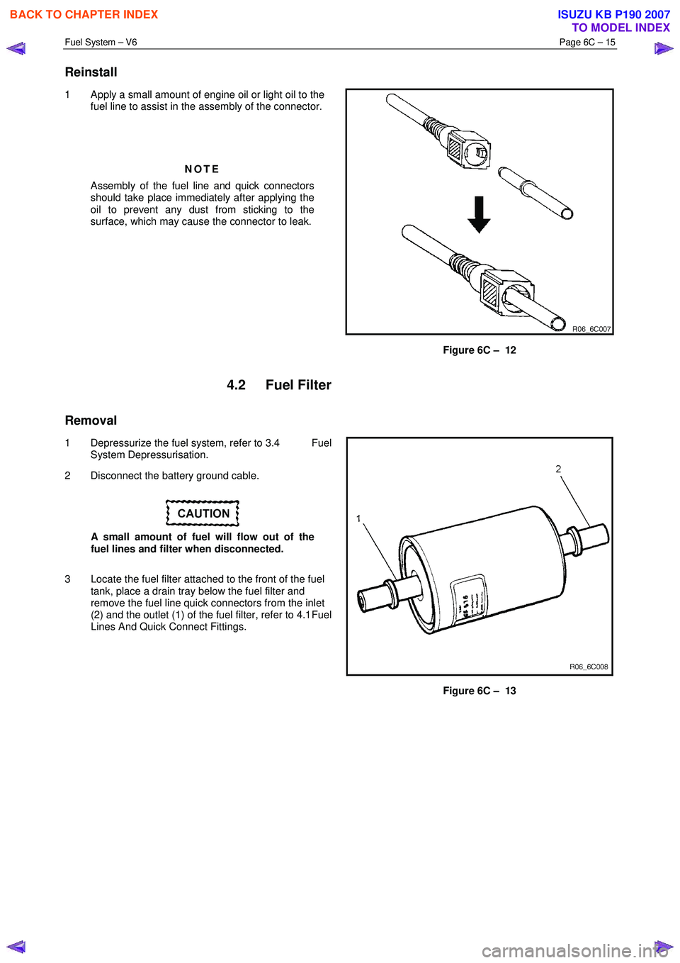
Reinstall
1 Apply a small amount of engine oil or light oil to the
fuel line to assist in the assembly of the connector.
NOTE
Assembly of the fuel line and quick connectors
should take place immediately after applying the
oil to prevent any dust from sticking to the
surface, which may cause the connector to leak.
Figure 6C – 12
4.2 Fuel Filter
Removal
1 Depressurize the fuel system, refer to 3.4 Fuel
System Depressurisation.
2 Disconnect the battery ground cable.
A small amount of fuel will flow out of the
fuel lines and filter when disconnected.
3 Locate the fuel filter attached to the front of the fuel tank, place a drain tray below the fuel filter and
remove the fuel line quick connectors from the inlet
(2) and the outlet (1) of the fuel filter, refer to 4.1 Fuel
Lines And Quick Connect Fittings.
Figure 6C – 13
BACK TO CHAPTER INDEX
TO MODEL INDEX
ISUZU KB P190 2007
Page 3223 of 6020
Fuel System – V6 Page 6C – 21
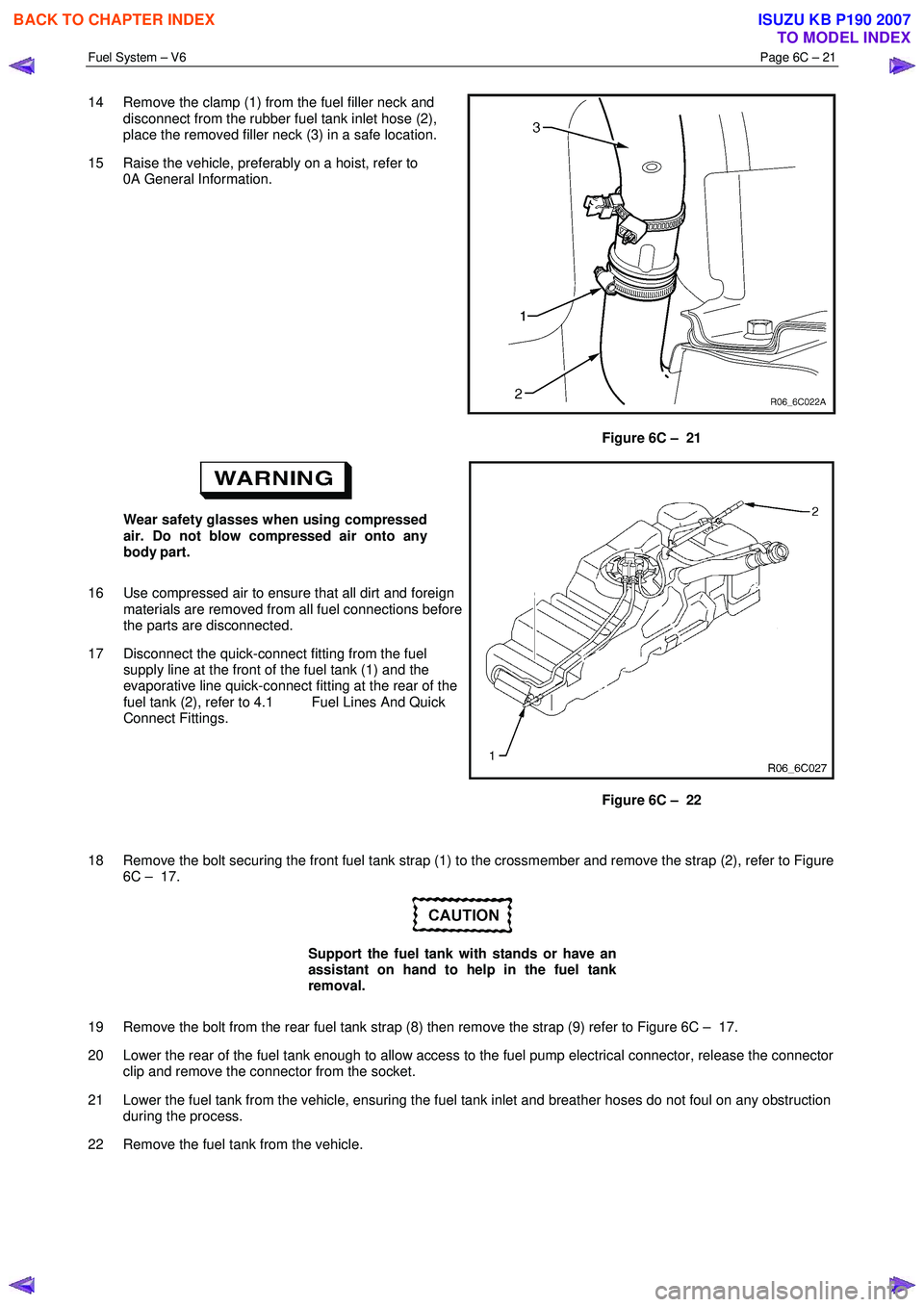
14 Remove the clamp (1) from the fuel filler neck and
disconnect from the rubber fuel tank inlet hose (2),
place the removed filler neck (3) in a safe location.
15 Raise the vehicle, preferably on a hoist, refer to 0A General Information.
Figure 6C – 21
Wear safety glasses when using compressed
air. Do not blow compressed air onto any
body part.
16 Use compressed air to ensure that all dirt and foreign materials are removed from all fuel connections before
the parts are disconnected.
17 Disconnect the quick-connect fitting from the fuel supply line at the front of the fuel tank (1) and the
evaporative line quick-connect fitting at the rear of the
fuel tank (2), refer to 4.1 Fuel Lines And Quick
Connect Fittings.
Figure 6C – 22
18 Remove the bolt securing the front fuel tank strap (1) to the crossmember and remove the strap (2), refer to Figure 6C – 17.
Support the fuel tank with stands or have an
assistant on hand to help in the fuel tank
removal.
19 Remove the bolt from the rear fuel tank strap (8) then remove the strap (9) refer to Figure 6C – 17.
20 Lower the rear of the fuel tank enough to allow access to the fuel pump electrical connector, release the connector clip and remove the connector from the socket.
21 Lower the fuel tank from the vehicle, ensuring the fuel tank inlet and breather hoses do not foul on any obstruction during the process.
22 Remove the fuel tank from the vehicle.
BACK TO CHAPTER INDEX
TO MODEL INDEX
ISUZU KB P190 2007
Page 3224 of 6020
Fuel System – V6 Page 6C – 22
Reinstall
Reinstallation of the fuel tank is the reverse of the removal procedure, noting the following:
1 Lift the fuel tank into position reinserting the fuel tank inlet and breather hoses into the body opening. Raise the fuel tank into place and rest the front of the tank on the crossmember.
2 Replace the fuel pump electrical connector, be sure to engage the locking tab.
3 Fit the fuel tank mounting straps in the following order, refer to Figure 6C – 17, a Loosely reattach the rear fuel tank mounting strap and bolt (8 & 9), refer to Figure 6C – 17.
b Loosely attach the front mounting strap and bolt (1 & 2), refer to Figure 6C – 17.
c Ensure that the fuel tank is located in the correct position then,
d Tighten the rear mounting strap bolt (8), Figure 6C – 17.
e Tighten the front mounting strap bolt (1), Figure 6C – 17.
4 Tighten all fuel tank mounting strap bolts to the correct torque specification.
Fuel tank mounting strap bolts
torque specification ............................................68.0 Nm
Install the fuel filter with the flow arrow on its
body pointing in the same direction as the
fuel flow to the front of the vehicle.
5 Install the disconnected quick-connect fittings to the fuel supply line at the front of the fuel tank and the evaporative line quick-connect fitting at the rear of the fuel tank. Refer to 4.1 Fuel Lines And Quick Connect Fittings, for the
correct component routeing.
6 Lower the vehicle to a comfortable working height and reinstall the clamp (1) to the fuel filler neck and reconnect the rubber fuel tank inlet hose (2) and tighten the clamp, refer to Figure 6C – 21.
7 Reinstall the fuel tank breather hose (3) to the fuel filler neck (1) and tighten the clamp (2), refer to Figure 6C – 20.
8 Clip the fuel filler door release cable (1) to the retainer on the fuel filler neck (2), refer to Figure 6C – 19.
9 Locate the fuel filler neck (3) to the filler pocket and attach with the securing screw (2), remove the cover material from the fuel filler neck inlet and refit the fuel filler cap (4), refer to Figure 6C – 18.
10 Reinstall the front half of the right-hand rear wheelhouse liner, refer to 10 Cab.
11 Before starting the vehicle, perform a fuel system leak test, refer to 3.3 Fuel Leak Test.
BACK TO CHAPTER INDEX
TO MODEL INDEX
ISUZU KB P190 2007
Page 3228 of 6020
Fuel System – V6 Page 6C – 26
Fuel vapour remains in the fuel tank even
when completely empty. Seal all openings in
the fuel tank using suitable material or a
plastic plug. Ensure no naked flames or other
ignition sources are nearby. Ensure all
cellular phones (and transmission devices
that may cause any metal objects to become
unintentional receiving antennas) are
switched off.
15 Place a suitable material over the opening in the fuel tank to prevent any foreign matter from entering the fuel system.
Fuel Level Sender Assembly
Test
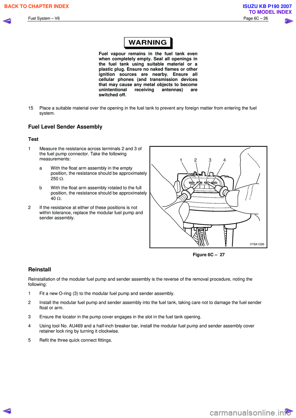
1 Measure the resistance across terminals 2 and 3 of the fuel pump connector. Take the following
measurements:
a W ith the float arm assembly in the empty position, the resistance should be approximately
250 Ω.
b W ith the float arm assembly rotated to the full position, the resistance should be approximately
40 Ω.
2 If the resistance at either of these positions is not within tolerance, replace the modular fuel pump and
sender assembly.
Figure 6C – 27
Reinstall
Reinstallation of the modular fuel pump and sender assembly is the reverse of the removal procedure, noting the
following:
1 Fit a new O-ring (3) to the modular fuel pump and sender assembly.
2 Install the modular fuel pump and sender assembly into the fuel tank, taking care not to damage the fuel sender float or arm.
3 Ensure the locator in the pump cover engages in the slot in the fuel tank opening.
4 Using tool No. AU469 and a half-inch breaker bar, install the modular fuel pump and sender assembly cover retainer lock ring by turning it clockwise.
5 Refit the three quick connect fittings.
BACK TO CHAPTER INDEX
TO MODEL INDEX
ISUZU KB P190 2007
Page 3231 of 6020
Fuel System – V6 Page 6C – 29
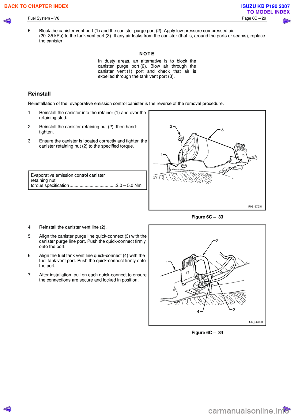
6 Block the canister vent port (1) and the canister purge port (2). Apply low-pressure compressed air
(20–35 kPa) to the tank vent port (3). If any air leaks from the canister (that is, around the ports or seams), replace
the canister.
NOTE
In dusty areas, an alternative is to block the
canister purge port (2). Blow air through the
canister vent (1) port and check that air is
expelled through the tank vent port (3).
Reinstall
Reinstallation of the evaporative emission control canister is the reverse of the removal procedure.
1 Reinstall the canister into the retainer (1) and over the retaining stud.
2 Reinstall the canister retaining nut (2), then hand- tighten.
3 Ensure the canister is located correctly and tighten the canister retaining nut (2) to the specified torque.
Evaporative emission control canister
retaining nut
torque specification .....................................2.0 – 5.0 Nm
Figure 6C – 33
4 Reinstall the canister vent line (2).
5 Align the canister purge line quick-connect (3) with the canister purge line port. Push the quick-connect firmly
onto the port.
6 Align the fuel tank vent line quick-connect (4) with the fuel tank vent port. Push the quick-connect firmly onto
the port.
7 After installation, pull on each quick-connect to ensure the connections are secure and locked in position.
Figure 6C – 34
BACK TO CHAPTER INDEX
TO MODEL INDEX
ISUZU KB P190 2007
Page 3233 of 6020
Fuel System – V6 Page 6C – 31
Fuel vapour remains in the fuel tank even
when completely empty. Seal all openings in
the fuel tank using suitable material or a
plastic plug. Ensure no naked flames or other
ignition sources are nearby. Ensure all
cellular phones (and transmission devices
that may cause any metal objects to become
unintentional receiving antennas) are
switched off.
Do not use excessive force when removing
the fuel siphon hose from the fuel filler neck.
If the fuel siphon hose gets stuck upon
removal, gently twist and tug the fuel siphon
hose back and forth until it releases.
NOTE
• If fuel does not siphon from the fuel tank, the
fuel siphon hose may have entered the fuel
tank through a roof-facing check valve
opening. If required, insert the J45004–1 fuel
siphon hose (1) into the fuel tank filler neck,
refer to Figure 6C – 35, but twist the fuel
siphon hose 90° as it slides down the filler
neck. This enables the fuel siphon hose to
enter the fuel tank through a floor-facing
check valve opening.
• The siphon procedure will not remove all fuel
from the fuel tank. If required, fuel remaining
in the fuel tank may be siphoned out through
the top of the fuel tank, once the modular fuel
pump and sender assembly is removed from
the tank, refer to 4.4 Fuel Tank.
8 Remove the siphon equipment.
BACK TO CHAPTER INDEX
TO MODEL INDEX
ISUZU KB P190 2007