Page 3234 of 6020

Fuel System – V6 Page 6C – 32
4.8 Fuel Filler Cap
The fuel filler cap is a 'screw on' type, with an integrated tightening torque limiting mechanism. W hen installing the fuel
filler cap, tighten it until a ratcheting (clicking) sound is audible, indicating the fuel filler cap is properly tightened. Th e fuel
filler cap is tethered to the fuel filler pocket.
Remove
The fuel filler cap requires a quarter of a turn anticlockwise to be removed.
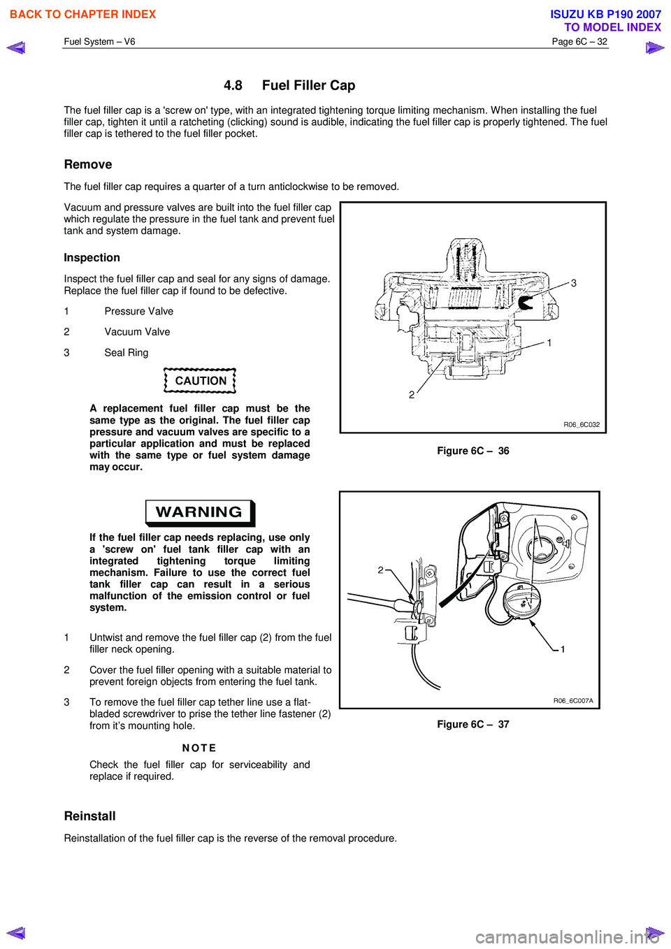
Vacuum and pressure valves are built into the fuel filler cap
which regulate the pressure in the fuel tank and prevent fuel
tank and system damage.
Inspection
Inspect the fuel filler cap and seal for any signs of damage.
Replace the fuel filler cap if found to be defective.
1 Pressure Valve
2 Vacuum Valve
3 Seal Ring
A replacement fuel filler cap must be the
same type as the original. The fuel filler cap
pressure and vacuum valves are specific to a
particular application and must be replaced
with the same type or fuel system damage
may occur.
Figure 6C – 36
If the fuel filler cap needs replacing, use only
a 'screw on' fuel tank filler cap with an
integrated tightening torque limiting
mechanism. Failure to use the correct fuel
tank filler cap can result in a serious
malfunction of the emission control or fuel
system.
1 Untwist and remove the fuel filler cap (2) from the fuel filler neck opening.
2 Cover the fuel filler opening with a suitable material to prevent foreign objects from entering the fuel tank.
3 To remove the fuel filler cap tether line use a flat- bladed screwdriver to prise the tether line fastener (2)
from it’s mounting hole.
NOTE
Check the fuel filler cap for serviceability and
replace if required.
Figure 6C – 37
Reinstall
Reinstallation of the fuel filler cap is the reverse of the removal procedure.
BACK TO CHAPTER INDEX
TO MODEL INDEX
ISUZU KB P190 2007
Page 3236 of 6020
Fuel System – V6 Page 6C – 34
Fuel Tank Lines
Figure 6C – 38
Legend
1 Fuel Feed Line
2 Fuel Return Line
3 Fuel Vapour emission port
4 Fuel Pump and Sender Assembly
5 Connector; Fuel Pump and Sender 6 Fuel Lines
7 Retainer Ring (Fuel Pump Lock)
8 “O” Ring Seal
9 Fuel Tank Assembly
10 Fuel Vapour Vent Line
Reinstall
Ensure the plastic fuel line clips are in good
condition before proceeding. If not, replace
the defective clips.
Reinstallation of the stone guard and fuel lines is the reverse of the removal procedure, noting the following:
1 Tighten the Fuel line securing nut to the correct torque specification, refer to Figure 6C – 39.
Fuel line securing nut
torque specification .........................................8 – 12 Nm
2 Tighten the stone guard securing bolts to the correct torque specification. Stone guard securing bolt
torque specification .....................................5.0 – 7.0 Nm
BACK TO CHAPTER INDEX
TO MODEL INDEX
ISUZU KB P190 2007
Page 5292 of 6020
8A-354 ELECTRICAL-BODY AND CHASSIS
Installation
To Install, follow the removal steps in the reverse order.
FUEL GAUGE UNIT
Removal
Dismount the fuel tank first, then remove the fuel gauge unit.
1. Remove the rear inner liner -LH
• Remove the clip
2. Remove the filler neck. • Remove the screw
3. Remove the ground with cable.
4. Remove the fuel tank band. • Disconnect fuel line quick connectors.
5. Remove the fuel gauge unit from the fuel tank.
BACK TO CHAPTER INDEX TO MODEL INDEXISUZU KB P190 2007