2007 ISUZU KB P190 fuel consumption
[x] Cancel search: fuel consumptionPage 4385 of 6020
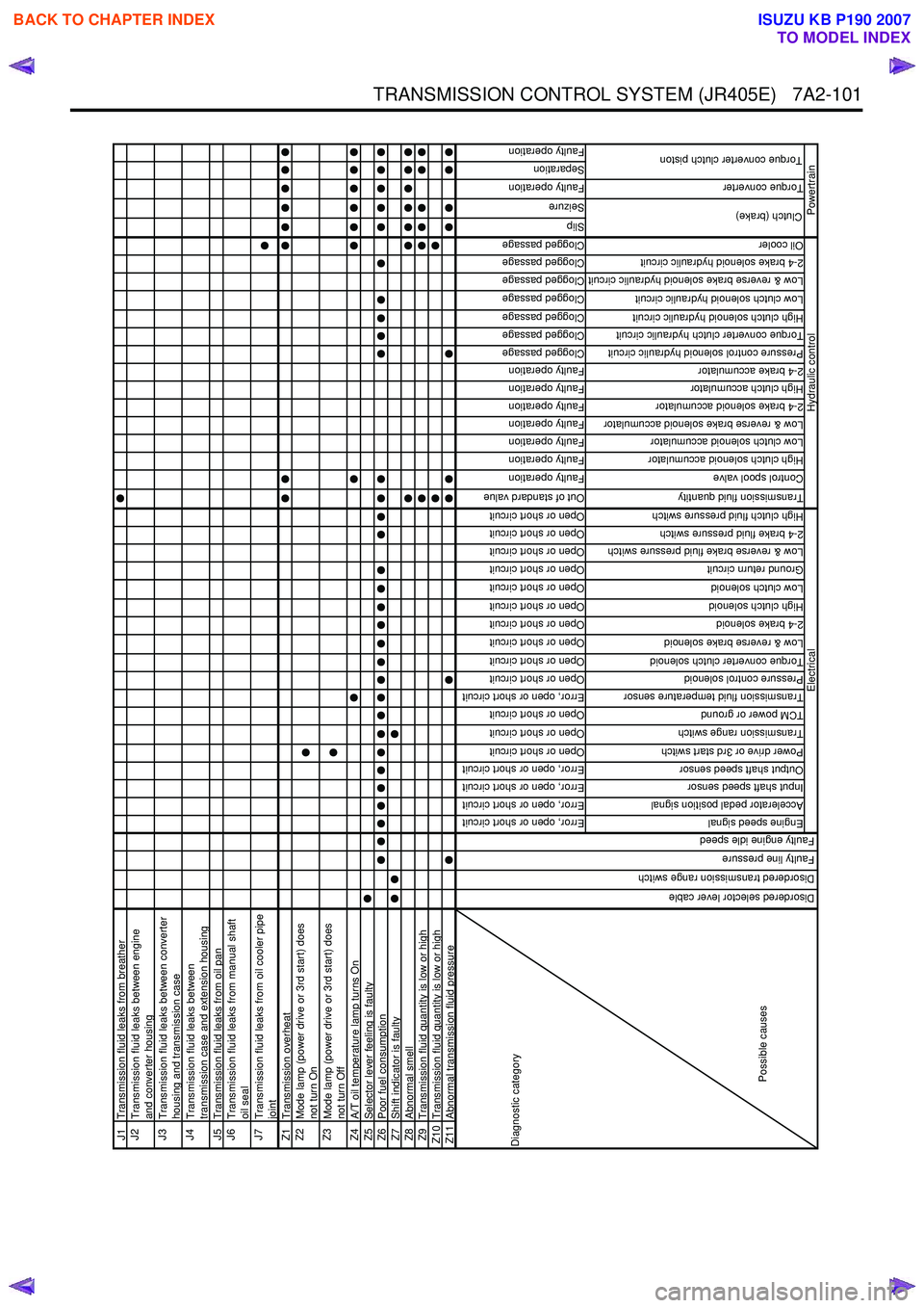
TRANSMISSION CONTROL SYSTEM (JR405E) 7A2-101
J1Transmission fluid leaks from breatherJ2
Transmission fluid leaks between engine
and converter housing
J3
Transmission fluid leaks between converter
housing and transmission case
J4
Transmission fluid leaks between
transmission case and extension housing
J5 Transmission fluid leaks from oil panJ6
Transmission fluid leaks from manual shaft
oil seal
J7
Transmission fluid leaks from oil cooler pipe
joint
Z1 Transmission overheatZ2
Mode lamp (power drive or 3rd start) does
not turn On
Z3
Mode lamp (power drive or 3rd start) does
not turn Off
Z4 A/T oil temperature lamp turns OnZ5Selector lever feeling is faultyZ6Poor fuel consumptionZ7Shift indicator is faultyZ8Abnormal smellZ9Transmission fluid quantity is low or highZ10 Transmission fluid quantity is low or highZ11Abnormal transmission fluid pressure
Error, open or short circuit
Error, open or short circuit
Error, open or short circuit
Error, open or short circuit
Open or short circuit
Open or short circuit
Open or short circuit
Error, open or short circuit
Open or short circuit
Open or short circuit
Open or short circuit
Open or short circuit
Open or short circuit
Open or short circuit
Open or short circuit
Open or short circuit
Open or short circuit
Open or short circuit
Out of standard value
Faulty operation
Faulty operation
Faulty operation
Faulty operation
Faulty operation
Faulty operation
Faulty operation
Clogged passage
Clogged passage
Clogged passage
Clogged passage
Clogged passage
Clogged passage
Clogged passage
Slip
Seizure
Faulty operation
Separation
Faulty operation
Engine speed signal
Accelerator pedal position signal
Input shaft speed sensor
Output shaft speed sensor
Power drive or 3rd start switch
Transmission range switch
TCM power or ground
Transmission fluid temperature sensor
Pressure control solenoid
Torque converter clutch solenoid
Low & reverse brake solenoid
2-4 brake solenoid
High clutch solenoid
Low clutch solenoid
Ground return circuit
Low & reverse brake fluid pressure switch
2-4 brake fluid pressure switch
High clutch fluid pressure switch
Transmission fluid quantity
Control spool valve
High clutch solenoid accumulator
Low clutch solenoid accumulator
Low & reverse brake solenoid accumulator
2-4 brake solenoid accumulator
High clutch accumulator
2-4 brake accumulator
Pressure control solenoid hydraulic circuit
Torque converter clutch hydraulic circuit
High clutch solenoid hydraulic circuit
Low clutch solenoid hydraulic circuit
Low & reverse brake solenoid hydraulic circuit
2-4 brake solenoid hydraulic circuit
Oil cooler
Torque converter
Clutch (brake)
Torque converter clutch piston
Hydraulic control
Powertrain
Diagnostic category
Possible causes
Electrical
Disordered selector lever cable
Disordered transmission range switch
Faulty line pressure
Faulty engine idle speed
BACK TO CHAPTER INDEX
TO MODEL INDEX
ISUZU KB P190 2007
Page 4403 of 6020
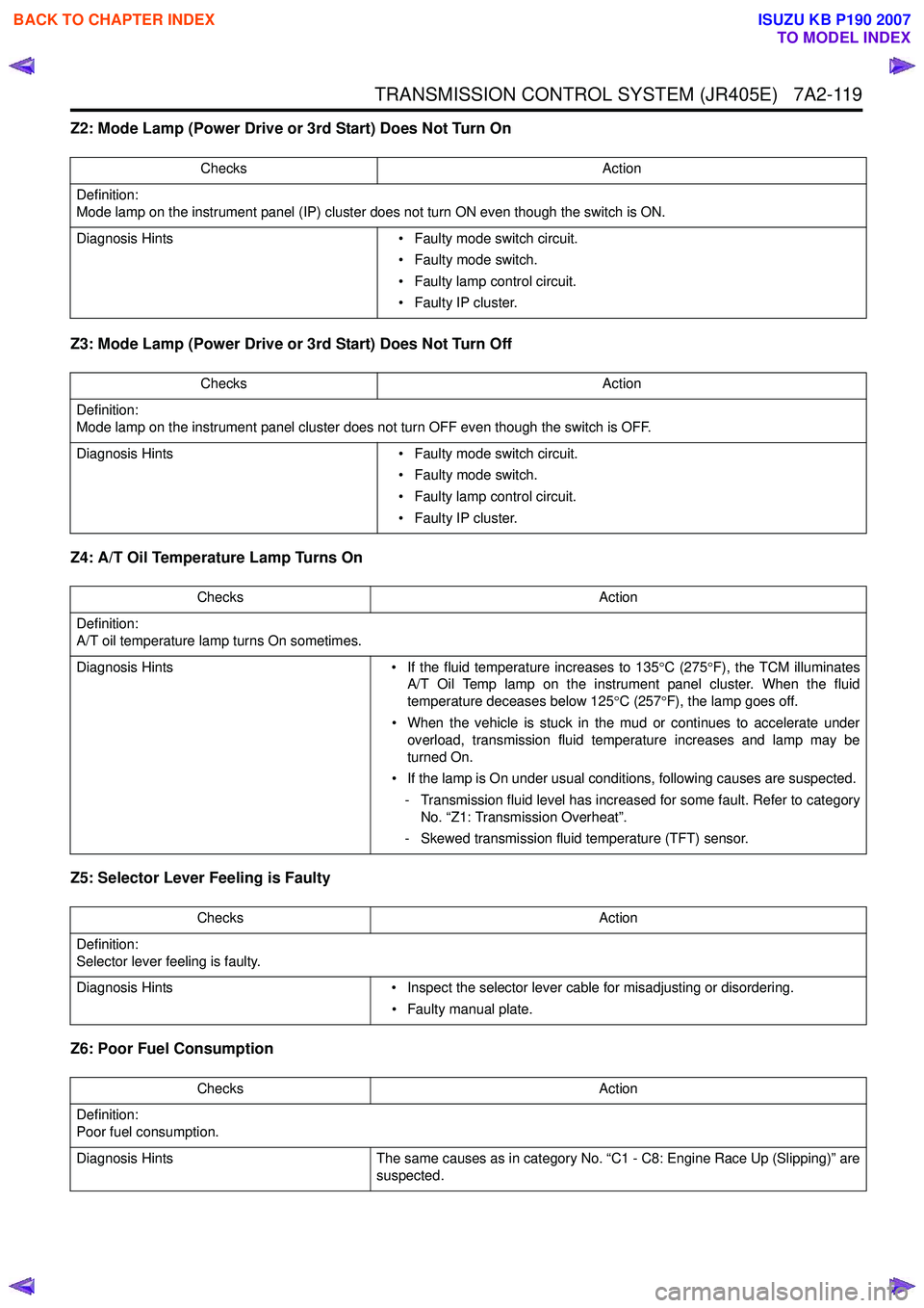
TRANSMISSION CONTROL SYSTEM (JR405E) 7A2-119
Z2: Mode Lamp (Power Drive or 3rd Start) Does Not Turn On
Z3: Mode Lamp (Power Drive or 3rd Start) Does Not Turn Off
Z4: A/T Oil Temperature Lamp Turns On
Z5: Selector Lever Feeling is Faulty
Z6: Poor Fuel Consumption
Checks Action
Definition:
Mode lamp on the instrument panel (IP) cluster does not turn ON even though the switch is ON.
Diagnosis Hints • Faulty mode switch circuit.
• Faulty mode switch.
• Faulty lamp control circuit.
• Faulty IP cluster.
Checks Action
Definition:
Mode lamp on the instrument panel cluster does not turn OFF even though the switch is OFF.
Diagnosis Hints • Faulty mode switch circuit.
• Faulty mode switch.
• Faulty lamp control circuit.
• Faulty IP cluster.
Checks Action
Definition:
A/T oil temperature lamp turns On sometimes.
Diagnosis Hints • If the fluid temperature increases to 135°C (275 °F), the TCM illuminates
A/T Oil Temp lamp on the instrument panel cluster. When the fluid
temperature deceases below 125 °C (257 °F), the lamp goes off.
• When the vehicle is stuck in the mud or continues to accelerate under overload, transmission fluid temperature increases and lamp may be
turned On.
• If the lamp is On under usual conditions, following causes are suspected. - Transmission fluid level has increased for some fault. Refer to category No. “Z1: Transmission Overheat”.
- Skewed transmission fluid temperature (TFT) sensor.
Checks Action
Definition:
Selector lever feeling is faulty.
Diagnosis Hints • Inspect the selector lever cable for misadjusting or disordering.
• Faulty manual plate.
Checks Action
Definition:
Poor fuel consumption.
Diagnosis Hints The same causes as in category No. “C1 - C8: Engine Race Up (Slipping)” are
suspected.
BACK TO CHAPTER INDEX
TO MODEL INDEX
ISUZU KB P190 2007
Page 5300 of 6020
8A-362 ELECTRICAL-BODY AND CHASSIS
Tachometer Off-Vehicle Inspection
Remove the tachometer from the meter assembly and
measure the resistance value and the current consumption
between each terminal.
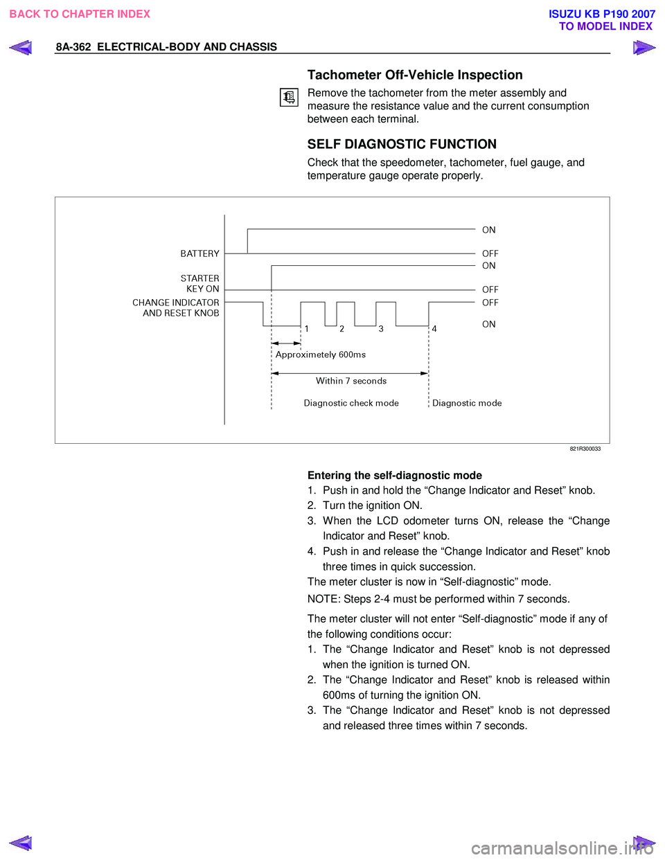
SELF DIAGNOSTIC FUNCTION
Check that the speedometer, tachometer, fuel gauge, and
temperature gauge operate properly.
821R300033
Entering the self-diagnostic mode
1. Push in and hold the “Change Indicator and Reset” knob.
2. Turn the ignition ON.
3. W hen the LCD odometer turns ON, release the “Change Indicator and Reset” knob.
4. Push in and release the “Change Indicator and Reset” knob three times in quick succession.
The meter cluster is now in “Self-diagnostic” mode.
NOTE: Steps 2-4 must be performed within 7 seconds.
The meter cluster will not enter “Self-diagnostic” mode if any of
the following conditions occur:
1. The “Change Indicator and Reset” knob is not depressed when the ignition is turned ON.
2. The “Change Indicator and Reset” knob is released within 600ms of turning the ignition ON.
3. The “Change Indicator and Reset” knob is not depressed and released three times within 7 seconds.
BACK TO CHAPTER INDEX TO MODEL INDEXISUZU KB P190 2007
Page 5303 of 6020
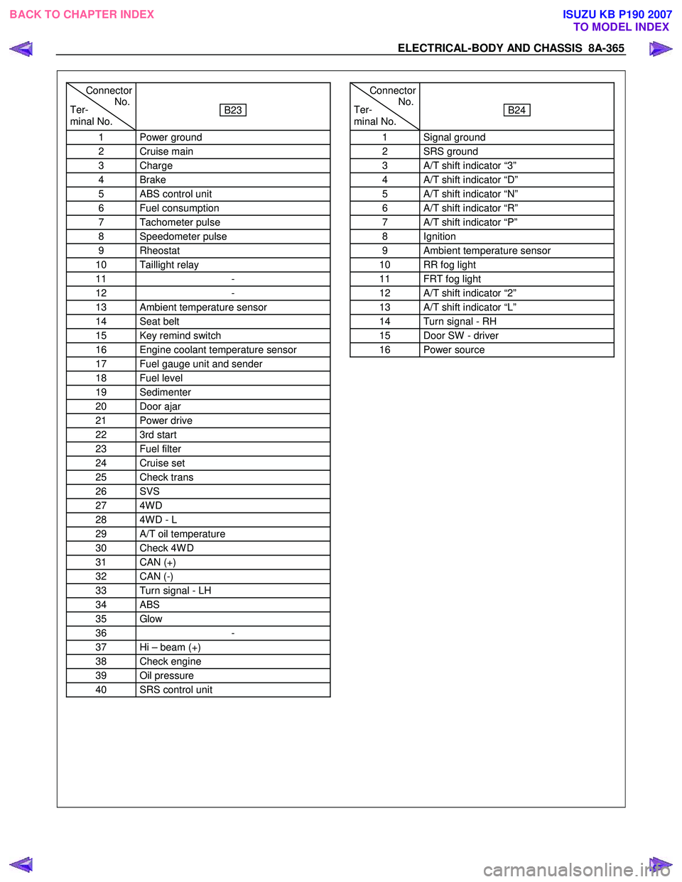
ELECTRICAL-BODY AND CHASSIS 8A-365
Connector
Ter- No.
minal No.
B23
1 Power ground
2 Cruise main
3 Charge
4 Brake
5 ABS control unit
6 Fuel consumption
7 Tachometer pulse
8 Speedometer pulse
9 Rheostat
10 Taillight relay
11 -
12 -
13 Ambient temperature sensor
14 Seat belt
15 Key remind switch
16 Engine coolant temperature sensor
17 Fuel gauge unit and sender
18 Fuel level
19 Sedimenter
20 Door ajar
21 Power drive
22 3rd start
23 Fuel filter
24 Cruise set
25 Check trans
26 SVS
27 4W D
28 4W D - L
29 A/T oil temperature
30 Check 4W D
31 CAN (+)
32 CAN (-)
33 Turn signal - LH
34 ABS
35 Glow
36 -
37 Hi – beam (+)
38 Check engine
39 Oil pressure
40 SRS control unit
Connector
Ter- No.
minal No.
B24
1 Signal ground
2 SRS ground
3 A/T shift indicator “3”
4 A/T shift indicator “D”
5 A/T shift indicator “N”
6 A/T shift indicator “R”
7 A/T shift indicator “P”
8 Ignition
9 Ambient temperature sensor
10 RR fog light
11 FRT fog light
12 A/T shift indicator “2”
13 A/T shift indicator “L”
14 Turn signal - RH
15 Door SW - driver
16 Power source
BACK TO CHAPTER INDEX TO MODEL INDEXISUZU KB P190 2007
Page 5304 of 6020
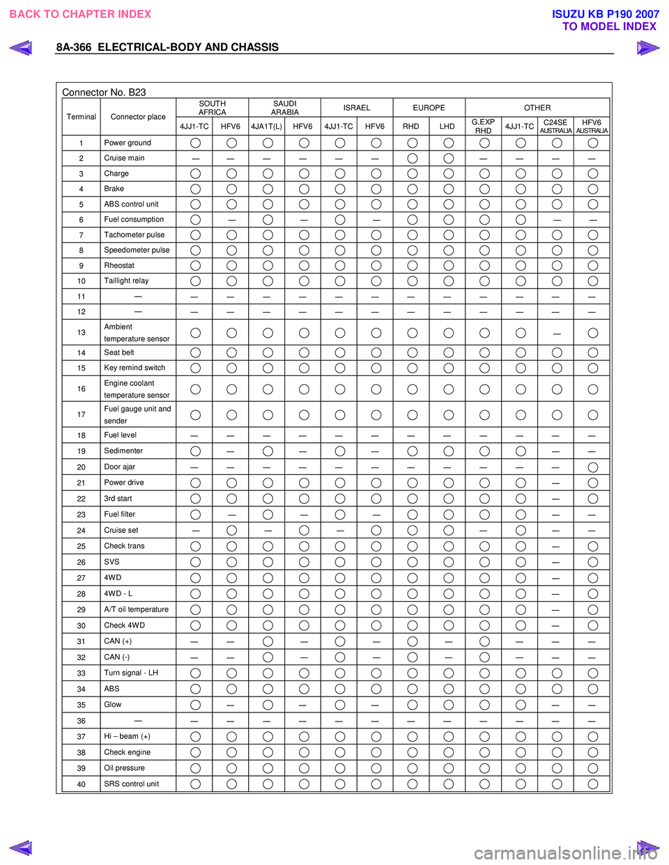
8A-366 ELECTRICAL-BODY AND CHASSIS
Connector No. B23 SOUTH
AFRICA SAUDI
ARABIA ISRAEL EUROPE OTHER
Terminal Connector place
4JJ1-TC HFV6 4JA1T(L) HFV6 4JJ1-TC HFV6 RHD LHD G.EXP
RHD 4JJ1-TC
C24SE
AUSTRALIAHFV6AUSTRALIA
1
Power ground
2 Cruise main
―
― ― ― ― ― ― ― ― ―
3
Charge
4 Brake
5 ABS control unit
6 Fuel consumption ―
―
―
―
―
7 Tachometer pulse
8 Speedometer pulse
9 Rheostat
10 Taillight relay
11 ―
― ― ― ― ― ― ― ― ― ― ― ―
12 ―
― ― ― ― ― ― ― ― ― ― ― ―
13 Ambient
temperature sensor ―
14 Seat belt
15 Key remind switch
16 Engine coolant
temperature sensor
17 Fuel gauge unit and
sender
18 Fuel level
― ― ― ― ― ― ― ― ― ― ― ―
19 Sedimenter ―
―
―
―
―
20 Door ajar
― ― ― ― ― ― ― ― ― ― ―
21 Power drive ―
22 3rd start ―
23 Fuel filter ―
―
―
―
―
24 Cruise set
― ―
―
―
―
―
25 Check trans ―
26 SVS ―
27 4W D ―
28 4W D - L ―
29 A/T oil temperature ―
30 Check 4W D ―
31 CAN (+)
― ― ―
―
―
― ― ―
32
CAN (-)
― ― ―
―
―
― ― ―
33
Turn signal - LH
34 ABS
35 Glow ―
―
―
―
―
36 ―
― ― ― ― ― ― ― ― ― ― ― ―
37 Hi – beam (+)
38 Check engine
39 Oil pressure
40 SRS control unit
BACK TO CHAPTER INDEX
TO MODEL INDEXISUZU KB P190 2007