2007 ISUZU KB P190 fuel consumption
[x] Cancel search: fuel consumptionPage 2013 of 6020
ENGINE DIAGNOSIS (C24SE) 6-13
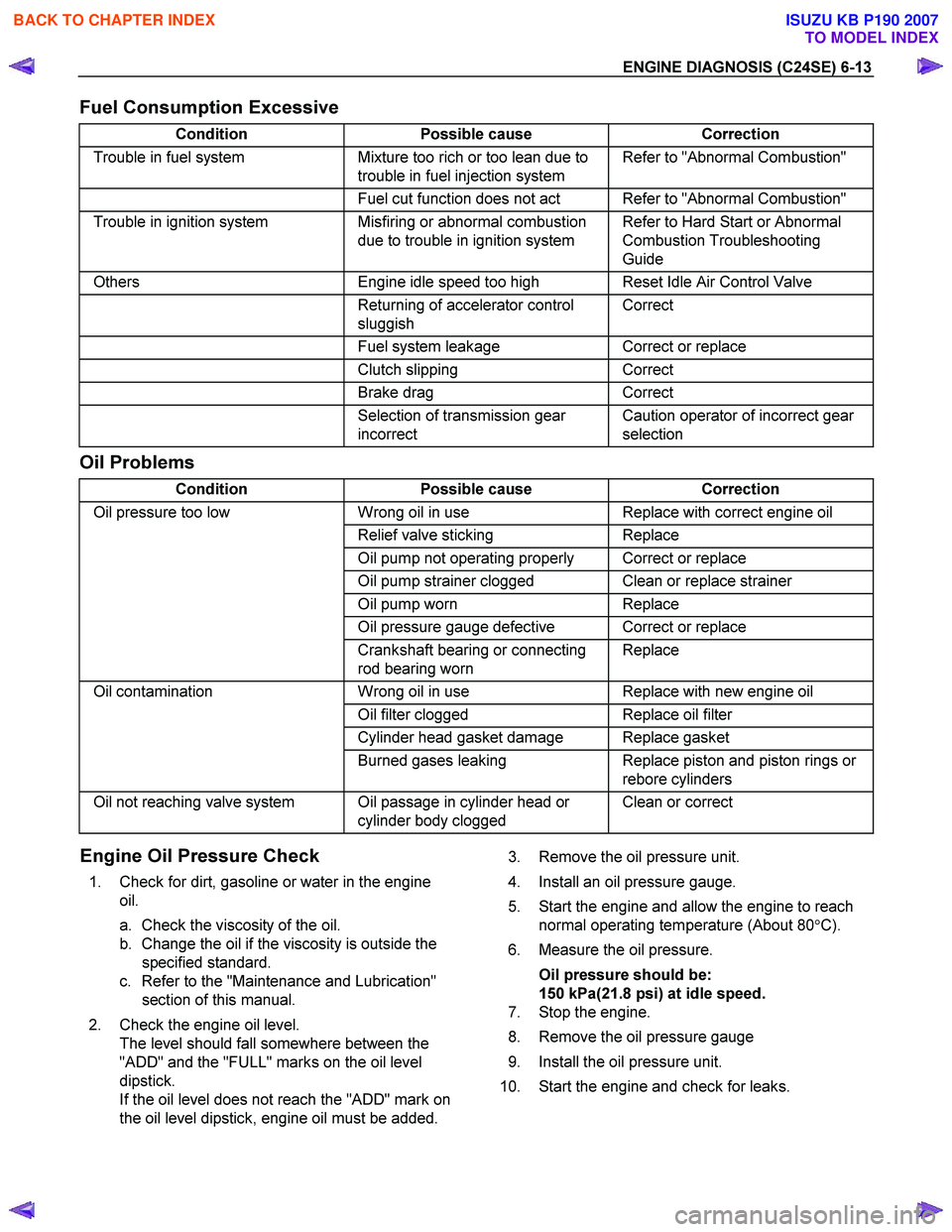
Fuel Consumption Excessive
Condition Possible cause Correction
Trouble in fuel system Mixture too rich or too lean due to
trouble in fuel injection system Refer to "Abnormal Combustion"
Fuel cut function does not act Refer to "Abnormal Combustion"
Trouble in ignition system Misfiring or abnormal combustion
due to trouble in ignition system Refer to Hard Start or Abnormal
Combustion Troubleshooting
Guide
Others Engine idle speed too high Reset Idle Air Control Valve
Returning of accelerator control
sluggish Correct
Fuel system leakage Correct or replace
Clutch slipping Correct
Brake drag Correct
Selection of transmission gear
incorrect Caution operator of incorrect gear
selection
Oil Problems
Condition Possible cause Correction
Oil pressure too low Wrong oil in use Replace with correct engine oil
Relief valve sticking Replace
Oil pump not operating properly Correct or replace
Oil pump strainer clogged Clean or replace strainer
Oil pump worn Replace
Oil pressure gauge defective Correct or replace
Crankshaft bearing or connecting
rod bearing worn Replace
Oil contamination
Wrong oil in use Replace with new engine oil
Oil filter clogged Replace oil filter
Cylinder head gasket damage Replace gasket
Burned gases leaking Replace piston and piston rings or
rebore cylinders
Oil not reaching valve system Oil passage in cylinder head or cylinder body clogged Clean or correct
Engine Oil Pressure Check
1. Check for dirt, gasoline or water in the engine
oil.
a. Check the viscosity of the oil.
b. Change the oil if the viscosity is outside the specified standard.
c. Refer to the "Maintenance and Lubrication" section of this manual.
2. Check the engine oil level. The level should fall somewhere between the
"ADD" and the "FULL" marks on the oil level
dipstick.
If the oil level does not reach the "ADD" mark on
the oil level dipstick, engine oil must be added.
3. Remove the oil pressure unit.
4. Install an oil pressure gauge.
5. Start the engine and allow the engine to reach normal operating temperature (About 80 °C).
6. Measure the oil pressure.
Oil pressure should be:
150 kPa(21.8 psi) at idle speed.
7. Stop the engine.
8. Remove the oil pressure gauge
9. Install the oil pressure unit.
10. Start the engine and check for leaks.
BACK TO CHAPTER INDEX
TO MODEL INDEX
ISUZU KB P190 2007
Page 3310 of 6020
Engine Management – V6 – Diagnostics Page 6C1-2–32
Checks Actions
Ignition System
• Inspect for moisture or corrosion around the spark plug / ignition coil area.
• Test the ignition coil voltage output. Refer to 6C1-3 Engine Management – V6 –
Service Operations.
• Remove and inspect the spark plugs. Refer to 6C1-3 Engine Management – V6 –
Service Operations.
NOTE
If the spark plugs are fouled, determine the cause of the fouling before
replacing the spark plugs, refer to 6C1-3 Engine Management – V6 –
Service Operations.
• Check for loose ignition coil ground circuit.
Engine Mechanical
• Check for the following engine mechanical fault condition. Refer to 6A1 Engine
Mechanical – V6.
• low engine compression, and
• worn valve train components.
Additional Checks
• Check the exhaust system for possible restrictions. Refer to 6F Exhaust System –
V6.
• Test for other TCM related faults that may cause the transmission to operate in
the default mode.
• Check for transmission mechanical faults that may produce similar symptoms
such as slipping clutch.
When all diagnosis and repairs are completed, check the system for correct operation.
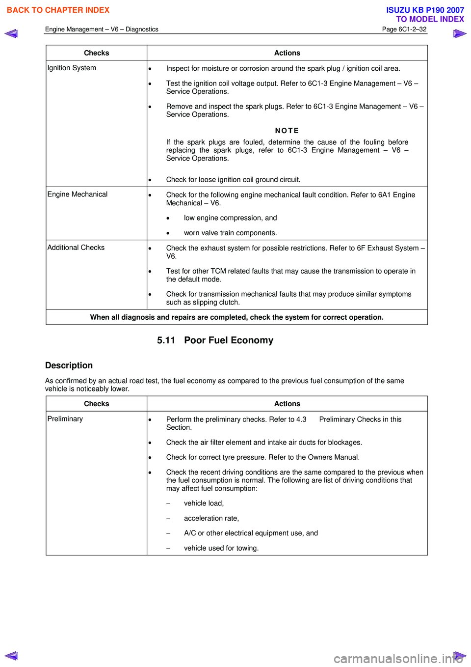
5.11 Poor Fuel Economy
Description
As confirmed by an actual road test, the fuel economy as compared to the previous fuel consumption of the same
vehicle is noticeably lower.
Checks Actions
Preliminary • Perform the preliminary checks. Refer to 4.3 Preliminary Checks in this
Section.
• Check the air filter element and intake air ducts for blockages.
• Check for correct tyre pressure. Refer to the Owners Manual.
• Check the recent driving conditions are the same compared to the previous when
the fuel consumption is normal. The following are list of driving conditions that
may affect fuel consumption:
− vehicle load,
− acceleration rate,
− A/C or other electrical equipment use, and
− vehicle used for towing.
BACK TO CHAPTER INDEX
TO MODEL INDEX
ISUZU KB P190 2007
Page 3369 of 6020
Engine Management – V6 – Diagnostics Page 6C1-2–91
Step Action Yes No
7 NOTE
If both DTCs are set, determine and correct the cause of
the contamination before replacing a sensor.
1 Inspect for the following conditions:
• Fuel contamination – refer to 6.5 Alcohol / Contaminants
in Fuel Diagnosis in this Section.
• The correct RTV sealant.
• Engine oil consumption – refer to 6A1 Engine Mechanical
– V6.
• Engine coolant consumption – refer to 6B1 Engine Cooling
– V6.
2 Replace the HO2S. Refer to 6C1-3 Engine Management – V6 – Service Operations.
Did you complete the replacement? Go to Step 8 —
8 1 Use Tech 2 to Clear the DTCs.
2 Turn OFF the ignition for 30 seconds.
3 Start the engine.
4 Operate the vehicle within the Conditions for Running the DTC. You may also operate the vehicle within the conditions that you
observed from the Freeze Frame / Failure Records.
Did the DTC fail this ignition? Go to Step 2 Go to Step 9
9 1 Using Tech 2, select the DTC display function.
Does Tech 2 display any DTCs? Go to the
appropriate DTC
Table in this Section System OK
When all diagnosis and repairs are completed, clear all DTCs and verify correct operation
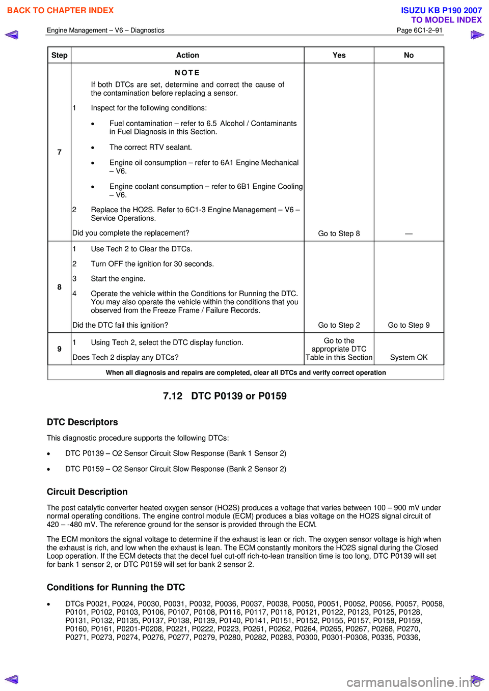
7.12 DTC P0139 or P0159
DTC Descriptors
This diagnostic procedure supports the following DTCs:
• DTC P0139 – O2 Sensor Circuit Slow Response (Bank 1 Sensor 2)
• DTC P0159 – O2 Sensor Circuit Slow Response (Bank 2 Sensor 2)
Circuit Description
The post catalytic converter heated oxygen sensor (HO2S) produces a voltage that varies between 100 – 900 mV under
normal operating conditions. The engine control module (ECM) produces a bias voltage on the HO2S signal circuit of
420 – -480 mV. The reference ground for the sensor is provided through the ECM.
The ECM monitors the signal voltage to determine if the exhaust is lean or rich. The oxygen sensor voltage is high when
the exhaust is rich, and low when the exhaust is lean. The ECM constantly monitors the HO2S signal during the Closed
Loop operation. If the ECM detects that the decel fuel cut-off rich-to-lean transition time is too long, DTC P0139 will set
for bank 1 sensor 2, or DTC P0159 will set for bank 2 sensor 2.
Conditions for Running the DTC
• DTCs P0021, P0024, P0030, P0031, P0032, P0036, P0037, P0038, P0050, P0051, P0052, P0056, P0057, P0058,
P0101, P0102, P0103, P0106, P0107, P0108, P0116, P0117, P0118, P0121, P0122, P0123, P0125, P0128,
P0131, P0132, P0135, P0137, P0138, P0139, P0140, P0141, P0151, P0152, P0155, P0157, P0158, P0159,
P0160, P0161, P0201-P0208, P0221, P0222, P0223, P0261, P0262, P0264, P0265, P0267, P0268, P0270,
P0271, P0273, P0274, P0276, P0277, P0279, P0280, P0282, P0283, P0300, P0301-P0308, P0335, P0336,
BACK TO CHAPTER INDEX
TO MODEL INDEX
ISUZU KB P190 2007
Page 3979 of 6020
TRANSMISSION CONTROL SYSTEM (AW30–40LE) 7A2-13
Item Description
Reverse lock out control If the select lever is moved to "R" position during forward driving, the TCM prohibits
reverse driving by turn off the S1 and turn on the S2 for prevention of danger and
protection of the automatic transmission.
1. Enable condition a) Vehicle speed is more than 11km/h (7mph).
2. Disable condition a) Vehicle speed is less than 9km/h (6mph).
b) W hen except "R" position is detected.
Auto cruise mode control If the auto cruise control can’t keep the setting speed like a uphill driving, the TCM selects the auto cruise mode shift pattern for downshifting, thus keeping the vehicle
speed.
W arm-up mode control TCM selects the warm-up mode shift pattern in engine cold condition for improvement of drivability and facilitation of warm-up.
Squat control W hen the TCM detects N→D garage shift, the TCM controls 1-3-1 shift by setting
timer, in order to improve the shift feel at N →D.
Coast down control The TCM switches to the coast down control at the coasting, in order to reduce the
roughness of shifting.
Uphill control W hen the TCM detected uphill, the TCM automatically switches to the uphill mode
in two-stage in proportion to inclination pitch to prevent the busy shifting and to
obtain an enough torque.
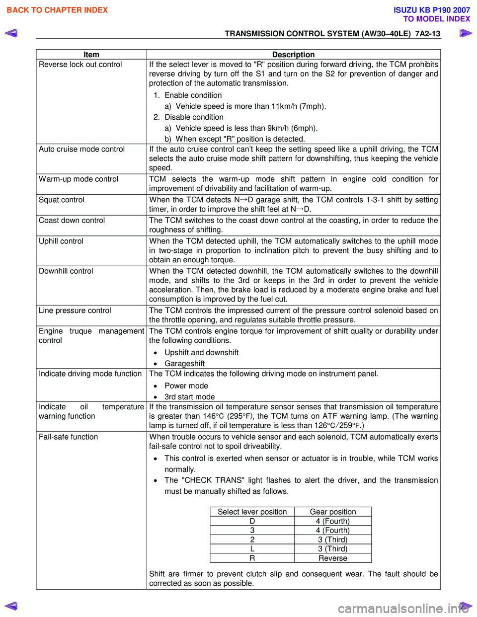
Downhill control W hen the TCM detected downhill, the TCM automatically switches to the downhill
mode, and shifts to the 3rd or keeps in the 3rd in order to prevent the vehicle
acceleration. Then, the brake load is reduced by a moderate engine brake and fuel
consumption is improved by the fuel cut.
Line pressure control The TCM controls the impressed current of the pressure control solenoid based on the throttle opening, and regulates suitable throttle pressure.
Engine truque management
control The TCM controls engine torque for improvement of shift quality or durability under
the following conditions.
• Upshift and downshift
• Garageshift
Indicate driving mode function The TCM indicates the following driving mode on instrument panel.
• Power mode
• 3rd start mode
Indicate oil temperature
warning function If the transmission oil temperature sensor senses that transmission oil temperature
is greater than 146 °C (295 °F) , the TCM turns on ATF warning lamp. (The warning
lamp is turned off, if oil temperature is less than 126 °C/ 259 °F .)
Fail-safe function W hen trouble occurs to vehicle sensor and each solenoid, TCM automatically exerts
fail-safe control not to spoil driveability.
• This control is exerted when sensor or actuator is in trouble, while TCM works
normally.
• The "CHECK TRANS" light flashes to alert the driver, and the transmission
must be manually shifted as follows.
Select lever position Gear position
D 4 (Fourth)
3 4 (Fourth)
2 3 (Third)
L 3 (Third)
R Reverse
Shift are firmer to prevent clutch slip and consequent wear. The fault should be
corrected as soon as possible.
BACK TO CHAPTER INDEX
TO MODEL INDEX
ISUZU KB P190 2007
Page 4029 of 6020
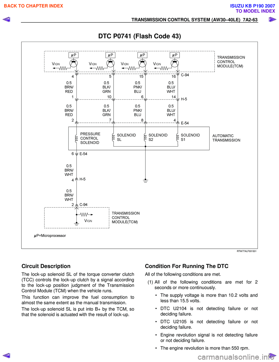
TRANSMISSION CONTROL SYSTEM (AW30–40LE) 7A2-63
DTC P0741 (Flash Code 43)
RTW 77ALF001501
Circuit Description
The lock-up solenoid SL of the torque converter clutch
(TCC) controls the lock-up clutch by a signal according
to the lock-up position judgment of the Transmission
Control Module (TCM) when the vehicle runs.
This function can improve the fuel consumption to
almost the same extent as the manual transmission.
The lock-up solenoid SL is put into B+ by the TCM, so
that the solenoid is actuated with the result of lock-up.
Condition For Running The DTC
All of the following conditions are met.
(1)
All of the following conditions are met for 2
seconds or more continuously.
• The supply voltage is more than 10.2 volts and less than 15.5 volts.
• DTC U2104 is not detecting failure or not deciding failure.
• DTC U2105 is not detecting failure or not deciding failure.
• Engine revolution signal is not detecting failure or not deciding failure.
• The engine revolution is more than 550 rpm.
BACK TO CHAPTER INDEX
TO MODEL INDEX
ISUZU KB P190 2007
Page 4033 of 6020
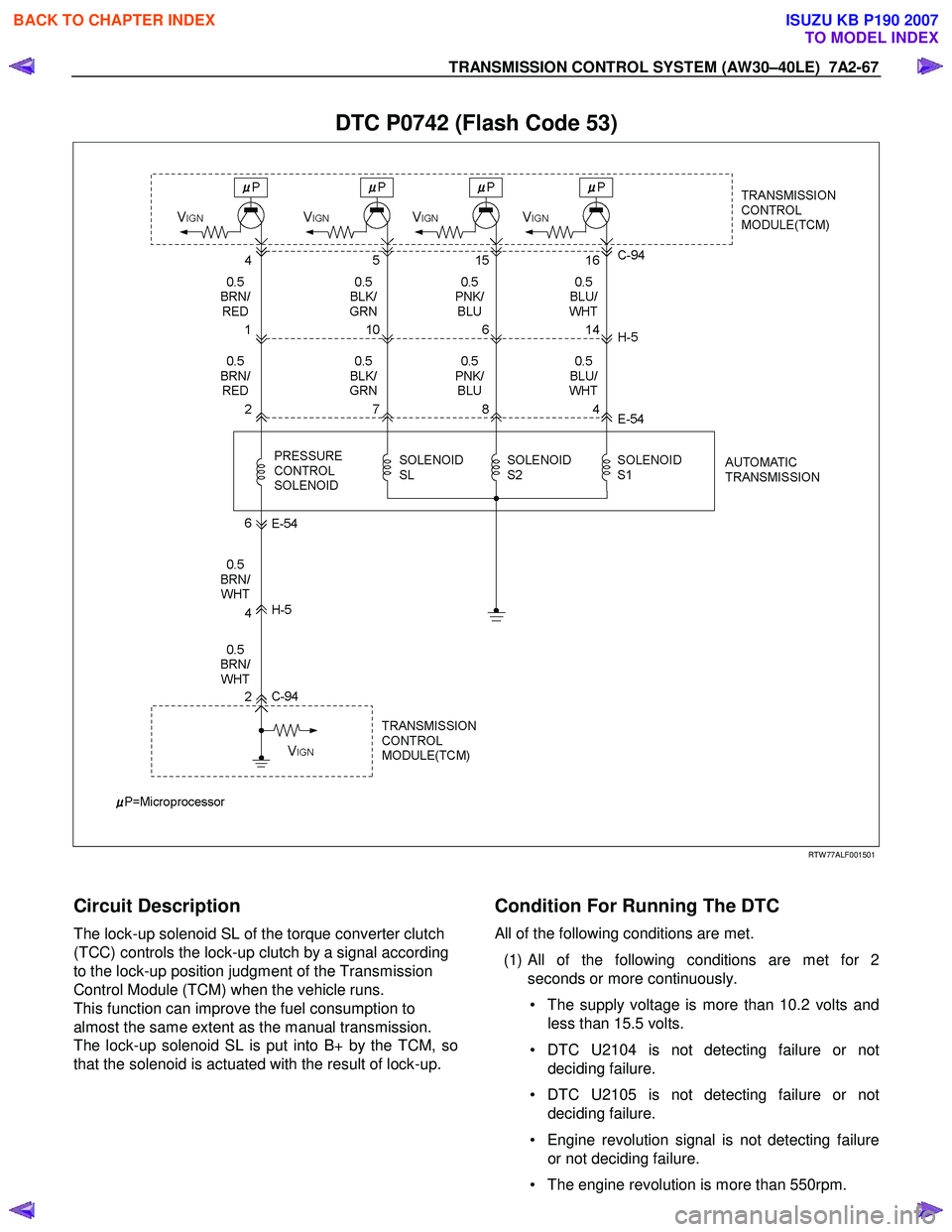
TRANSMISSION CONTROL SYSTEM (AW30–40LE) 7A2-67
DTC P0742 (Flash Code 53)
RTW 77ALF001501
Circuit Description
The lock-up solenoid SL of the torque converter clutch
(TCC) controls the lock-up clutch by a signal according
to the lock-up position judgment of the Transmission
Control Module (TCM) when the vehicle runs.
This function can improve the fuel consumption to
almost the same extent as the manual transmission.
The lock-up solenoid SL is put into B+ by the TCM, so
that the solenoid is actuated with the result of lock-up.
Condition For Running The DTC
All of the following conditions are met.
(1)
All of the following conditions are met for 2
seconds or more continuously.
• The supply voltage is more than 10.2 volts and less than 15.5 volts.
• DTC U2104 is not detecting failure or not deciding failure.
• DTC U2105 is not detecting failure or not deciding failure.
• Engine revolution signal is not detecting failure or not deciding failure.
• The engine revolution is more than 550rpm.
BACK TO CHAPTER INDEX
TO MODEL INDEX
ISUZU KB P190 2007
Page 4071 of 6020
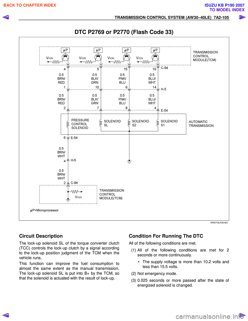
TRANSMISSION CONTROL SYSTEM (AW30–40LE) 7A2-105
DTC P2769 or P2770 (Flash Code 33)
RTW 77ALF001501
Circuit Description
The lock-up solenoid SL of the torque converter clutch
(TCC) controls the lock-up clutch by a signal according
to the lock-up position judgment of the TCM when the
vehicle runs.
This function can improve the fuel consumption to
almost the same extent as the manual transmission.
The lock-up solenoid SL is put into B+ by the TCM, so
that the solenoid is actuated with the result of lock-up.
Condition For Running The DTC
All of the following conditions are met.
(1) All of the following conditions are met for 2 seconds or more continuously.
• The supply voltage is more than 10.2 volts and
less than 15.5 volts.
(2) Not emergency mode.
(3) 0.025 seconds or more passed after the state o
f
energized solenoid is changed.
BACK TO CHAPTER INDEX
TO MODEL INDEX
ISUZU KB P190 2007
Page 4381 of 6020
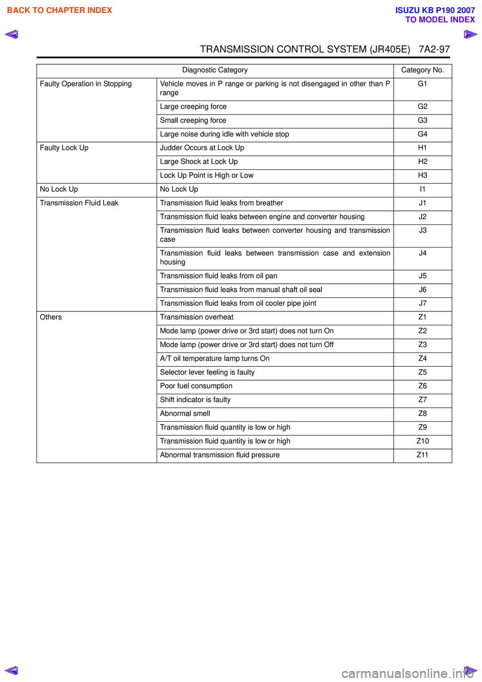
TRANSMISSION CONTROL SYSTEM (JR405E) 7A2-97
Faulty Operation in Stopping Vehicle moves in P range or parking is not disengaged in other than Prange G1
Large creeping force G2
Small creeping force G3
Large noise during idle with vehicle stop G4
Faulty Lock Up Judder Occurs at Lock Up H1
Large Shock at Lock Up H2
Lock Up Point is High or Low H3
No Lock Up No Lock Up I1
Transmission Fluid Leak Transmission fluid leaks from breather J1
Transmission fluid leaks between engine and converter housing J2
Transmission fluid leaks between converter housing and transmission
case J3
Transmission fluid leaks between transmission case and extension
housing J4
Transmission fluid leaks from oil pan J5
Transmission fluid leaks from manual shaft oil seal J6
Transmission fluid leaks from oil cooler pipe joint J7
Others Transmission overheat Z1
Mode lamp (power drive or 3rd start) does not turn On Z2
Mode lamp (power drive or 3rd start) does not turn Off Z3
A/T oil temperature lamp turns On Z4
Selector lever feeling is faulty Z5
Poor fuel consumption Z6
Shift indicator is faulty Z7
Abnormal smell Z8
Transmission fluid quantity is low or high Z9
Transmission fluid quantity is low or high Z10
Abnormal transmission fluid pressure Z11
Diagnostic Category
Category No.
BACK TO CHAPTER INDEX
TO MODEL INDEX
ISUZU KB P190 2007