2007 ISUZU KB P190 drain bolt
[x] Cancel search: drain boltPage 1994 of 6020
EXHAUST SYSTEM (4JK1/4JJ1) 6F-9
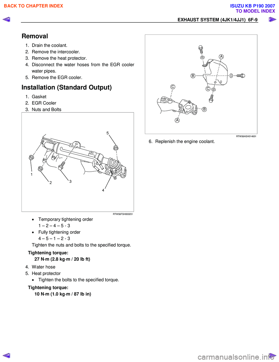
Removal
1. Drain the coolant.
2. Remove the intercooler.
3. Remove the heat protector.
4. Disconnect the water hoses from the EGR coole
r
water pipes.
5. Remove the EGR cooler.
Installation (Standard Output)
1. Gasket
2. EGR Cooler
3. Nuts and Bolts
RTW 56FSH000201
• Temporary tightening order
1 – 2 – 4 – 5 - 3
• Fully tightening order
4 – 5 – 1 – 2 - 3
Tighten the nuts and bolts to the specified torque.
Tightening torque: 27 N ⋅
⋅⋅
⋅
m (2.8 kg ⋅
⋅⋅
⋅
m / 20 lb ft)
4. W ater hose
5. Heat protector • Tighten the bolts to the specified torque.
Tightening torque: 10 N ⋅
⋅⋅
⋅
m (1.0 kg ⋅
⋅⋅
⋅
m / 87 lb in)
RTW 56ASH014601
6. Replenish the engine coolant.
BACK TO CHAPTER INDEX
TO MODEL INDEX
ISUZU KB P190 2007
Page 2012 of 6020
6-12 ENGINE DIAGNOSIS (C24SE)
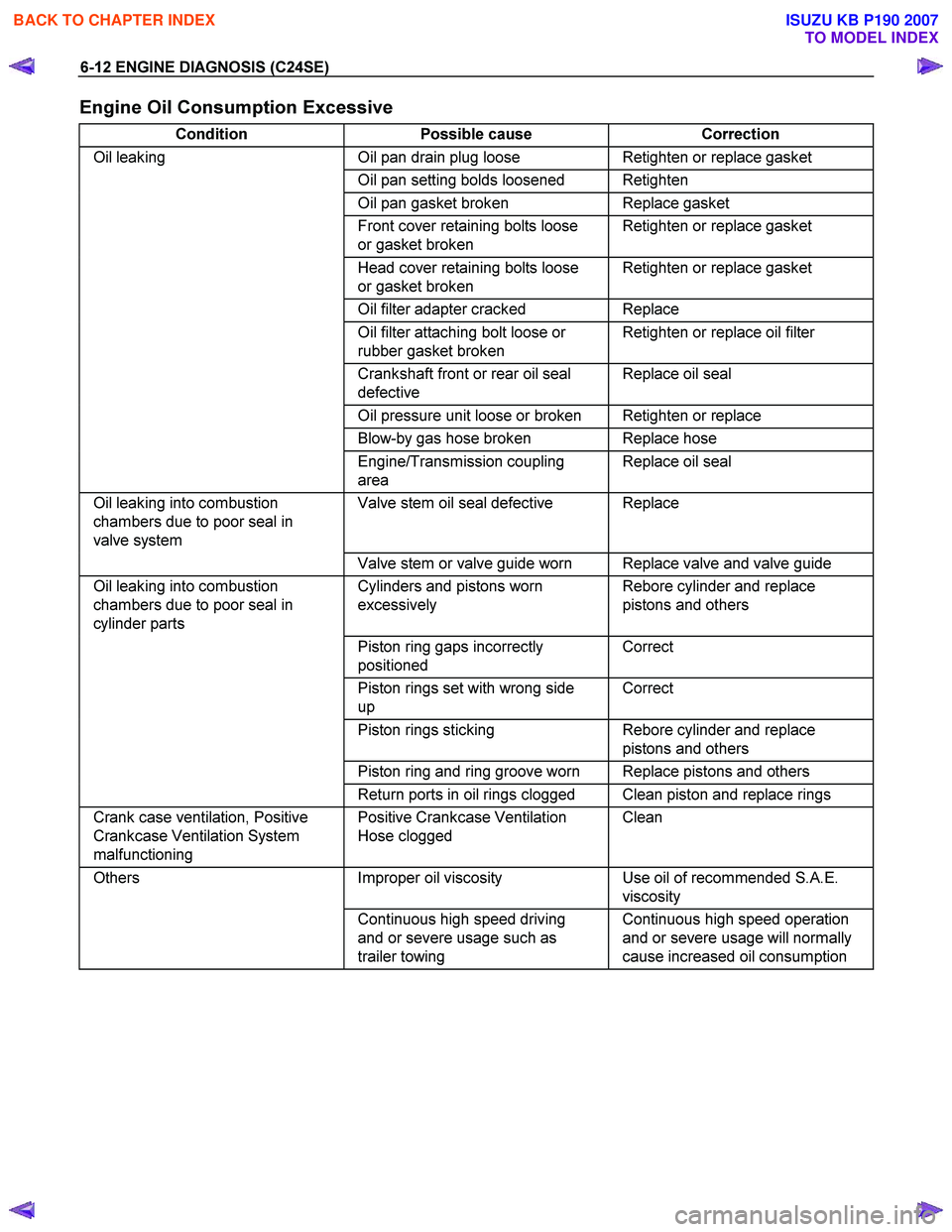
Engine Oil Consumption Excessive
Condition Possible cause Correction
Oil leaking Oil pan drain plug loose Retighten or replace gasket
Oil pan setting bolds loosened Retighten
Oil pan gasket broken Replace gasket
Front cover retaining bolts loose
or gasket broken Retighten or replace gasket
Head cover retaining bolts loose
or gasket broken Retighten or replace gasket
Oil filter adapter cracked Replace
Oil filter attaching bolt loose or
rubber gasket broken Retighten or replace oil filter
Crankshaft front or rear oil seal
defective Replace oil seal
Oil pressure unit loose or broken Retighten or replace
Blow-by gas hose broken Replace hose
Engine/Transmission coupling
area Replace oil seal
Oil leaking into combustion
chambers due to poor seal in
valve system Valve stem oil seal defective Replace
Valve stem or valve guide worn Replace valve and valve guide
Oil leaking into combustion
chambers due to poor seal in
cylinder parts Cylinders and pistons worn
excessively Rebore cylinder and replace
pistons and others
Piston ring gaps incorrectly
positioned Correct
Piston rings set with wrong side
up Correct
Piston rings sticking Rebore cylinder and replace
pistons and others
Piston ring and ring groove worn Replace pistons and others
Return ports in oil rings clogged Clean piston and replace rings
Crank case ventilation, Positive
Crankcase Ventilation System
malfunctioning Positive Crankcase Ventilation
Hose clogged Clean
Others
Improper oil viscosity Use oil of recommended S.A.E.
viscosity
Continuous high speed driving
and or severe usage such as
trailer towing Continuous high speed operation
and or severe usage will normally
cause increased oil consumption
BACK TO CHAPTER INDEX
TO MODEL INDEX
ISUZU KB P190 2007
Page 2041 of 6020
ENGINE MECHANICAL (C24SE) 6A-27
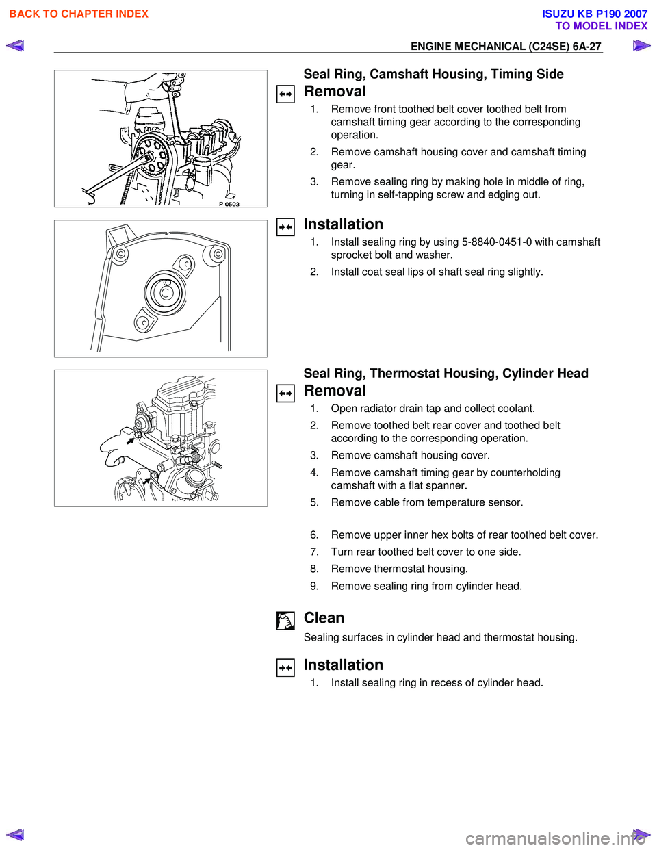
Seal Ring, Camshaft Housing, Timing Side
Removal
1. Remove front toothed belt cover toothed belt from camshaft timing gear according to the corresponding
operation.
2. Remove camshaft housing cover and camshaft timing gear.
3. Remove sealing ring by making hole in middle of ring, turning in self-tapping screw and edging out.
Installation
1. Install sealing ring by using 5-8840-0451-0 with camshaft sprocket bolt and washer.
2. Install coat seal lips of shaft seal ring slightly.
Seal Ring, Thermostat Housing, Cylinder Head
Removal
1. Open radiator drain tap and collect coolant.
2. Remove toothed belt rear cover and toothed belt according to the corresponding operation.
3. Remove camshaft housing cover.
4. Remove camshaft timing gear by counterholding camshaft with a flat spanner.
5. Remove cable from temperature sensor.
6. Remove upper inner hex bolts of rear toothed belt cover.
7. Turn rear toothed belt cover to one side.
8. Remove thermostat housing.
9. Remove sealing ring from cylinder head.
Clean
Sealing surfaces in cylinder head and thermostat housing.
Installation
1. Install sealing ring in recess of cylinder head.
BACK TO CHAPTER INDEX
TO MODEL INDEX
ISUZU KB P190 2007
Page 2049 of 6020
ENGINE MECHANICAL (C24SE) 6A-35
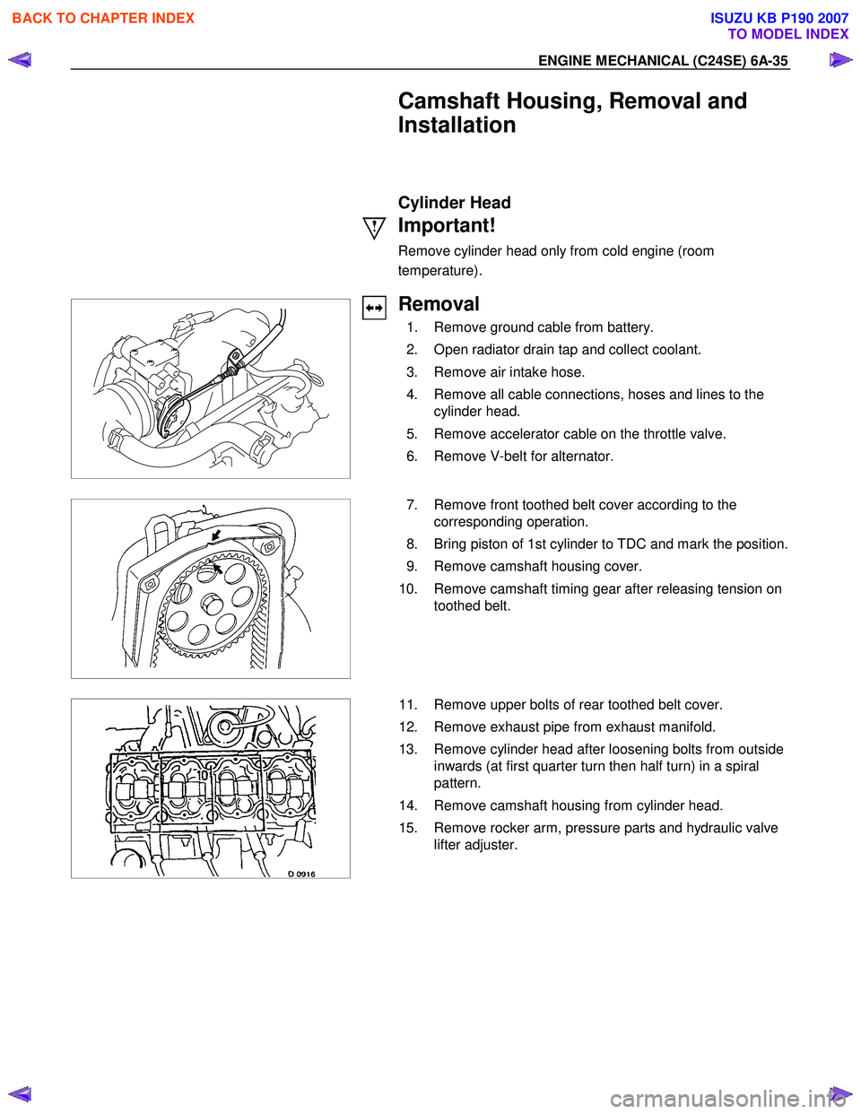
Camshaft Housing, Removal and
Installation
Cylinder Head
Important!
Remove cylinder head only from cold engine (room
temperature).
Removal
1. Remove ground cable from battery.
2. Open radiator drain tap and collect coolant.
3. Remove air intake hose.
4. Remove all cable connections, hoses and lines to the cylinder head.
5. Remove accelerator cable on the throttle valve.
6. Remove V-belt for alternator.
7. Remove front toothed belt cover according to the
corresponding operation.
8. Bring piston of 1st cylinder to TDC and mark the position.
9. Remove camshaft housing cover.
10. Remove camshaft timing gear after releasing tension on toothed belt.
11. Remove upper bolts of rear toothed belt cover.
12. Remove exhaust pipe from exhaust manifold.
13. Remove cylinder head after loosening bolts from outside inwards (at first quarter turn then half turn) in a spiral
pattern.
14. Remove camshaft housing from cylinder head.
15. Remove rocker arm, pressure parts and hydraulic valve lifter adjuster.
BACK TO CHAPTER INDEX
TO MODEL INDEX
ISUZU KB P190 2007
Page 2102 of 6020
6A-88 ENGINE MECHANICAL (C24SE)
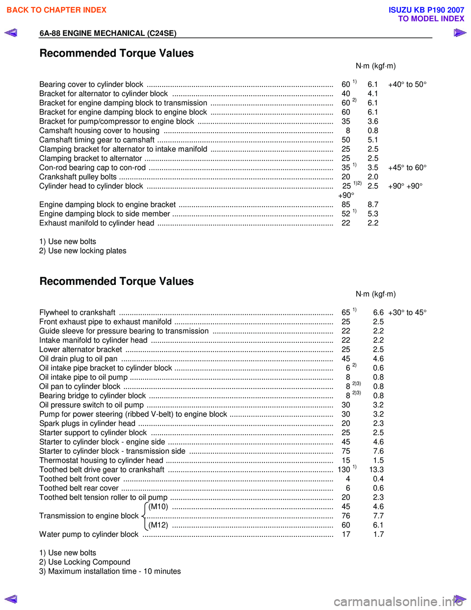
Recommended Torque Values
N⋅m (kgf ⋅m)
Bearing cover to cylinder block ........................................................................................ 60
1) 6.1 +40 ° to 50 °
Bracket for alternator to cylinder block ............................................................................ 40 4.1
Bracket for engine damping block to transmission .......................................................... 60
2) 6.1
Bracket for engine damping block to engine block .......................................................... 60 6.1
Bracket for pump/compressor to engine block ................................................................ 35 3.6
Camshaft housing cover to housing ................................................................................ 8 0.8
Camshaft timing gear to camshaft ................................................................................... 50 5.1
Clamping bracket for alternator to intake manifold .......................................................... 25 2.5
Clamping bracket to alternator ......................................................................................... 25 2.5
Con-rod bearing cap to con-rod ....................................................................................... 35
1) 3.5 +45 ° to 60 °
Crankshaft pulley bolts ..................................................................................................... 2 0 2.0
Cylinder head to cylinder block ........................................................................................ 25
1)2) 2.5 +90 ° +90 °
+90 °
Engine damping block to engine bracket ......................................................................... 85 8.7
Engine damping block to side member ............................................................................ 52
1) 5.3
Exhaust manifold to cylinder head ................................................................................... 22 2.2
1) Use new bolts
2) Use new locking plates
Recommended Torque Values
N⋅m (kgf ⋅m)
Flywheel to crankshaft ..................................................................................................... 65
1) 6.6 +30° to 45 °
Front exhaust pipe to exhaust manifold ........................................................................... 25 2.5
Guide sleeve for pressure bearing to transmission ......................................................... 22 2.2
Intake manifold to cylinder head ...................................................................................... 22 2.2
Lower alternator bracket .................................................................................................. 25 2.5
Oil drain plug to oil pan .................................................................................................... 45 4.6
Oil intake pipe bracket to cylinder block ........................................................................... 6
2) 0.6
Oil intake pipe to oil pump ................................................................................................ 8 0.8
Oil pan to cylinder block ................................................................................................... 8
2)3) 0.8
Bearing bridge to cylinder block ....................................................................................... 8 2)3) 0.8
Oil pressure switch to oil pump ........................................................................................ 30 3.2
Pump for power steering (ribbed V-belt) to engine block ................................................. 30 3.2
Spark plugs in cylinder head ............................................................................................ 20 2. 3
Starter support to cylinder block ...................................................................................... 25 2.5
Starter to cylinder block - engine side .............................................................................. 45 4.6
Starter to cylinder block - transmission side .................................................................... 75 7.6
Thermostat housing to cylinder head ............................................................................... 15 1.5
Toothed belt drive gear to crankshaft .............................................................................. 130
1) 13.3
Toothed belt front cover ................................................................................................... 4 0.4
Toothed belt rear cover .................................................................................................... 6 0.6
Toothed belt tension roller to oil pump ............................................................................. 20 2.3 (M10) ............................................................................ 45 4.6
Transmission to engine block ......................................................................................... 76 7.7 (M12) ............................................................................ 60 6.1
W ater pump to cylinder block .......................................................................................... 17 1.7
1) Use new bolts
2) Use Locking Compound
3) Maximum installation time - 10 minutes
BACK TO CHAPTER INDEX
TO MODEL INDEX
ISUZU KB P190 2007
Page 2111 of 6020
ENGINE COOLING 6B-7
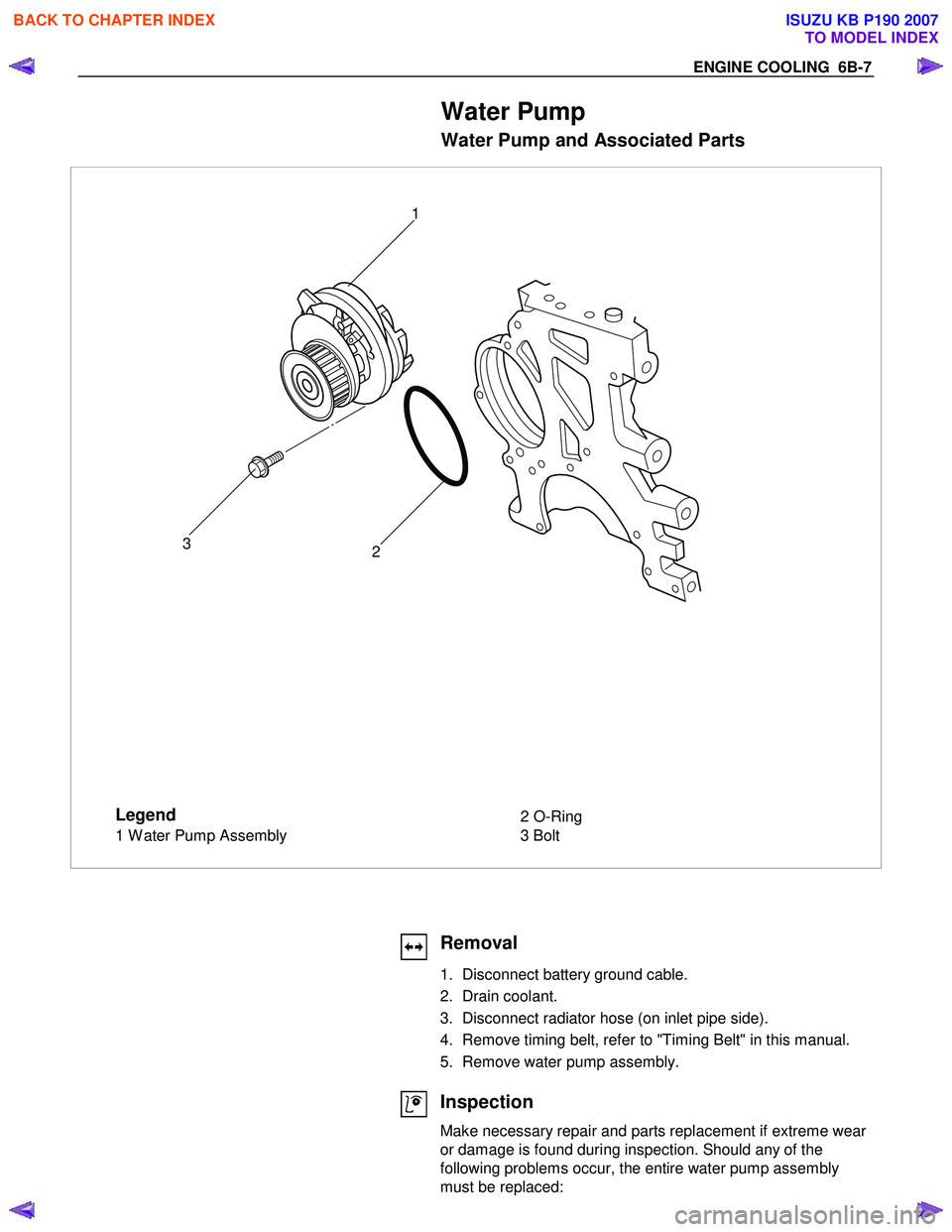
Water Pump
Water Pump and Associated Parts
Legend
1 Water Pump Assembly 2 O-Ring
3 Bolt
2
3 1
Removal
1. Disconnect battery ground cable.
2. Drain coolant.
3. Disconnect radiator hose (on inlet pipe side).
4. Remove timing belt, refer to "Timing Belt" in this manual.
5. Remove water pump assembly.
Inspection
Make necessary repair and parts replacement if extreme wear
or damage is found during inspection. Should any of the
following problems occur, the entire water pump assembly
must be replaced:
BACK TO CHAPTER INDEX
TO MODEL INDEX
ISUZU KB P190 2007
Page 2113 of 6020
ENGINE COOLING 6B-9
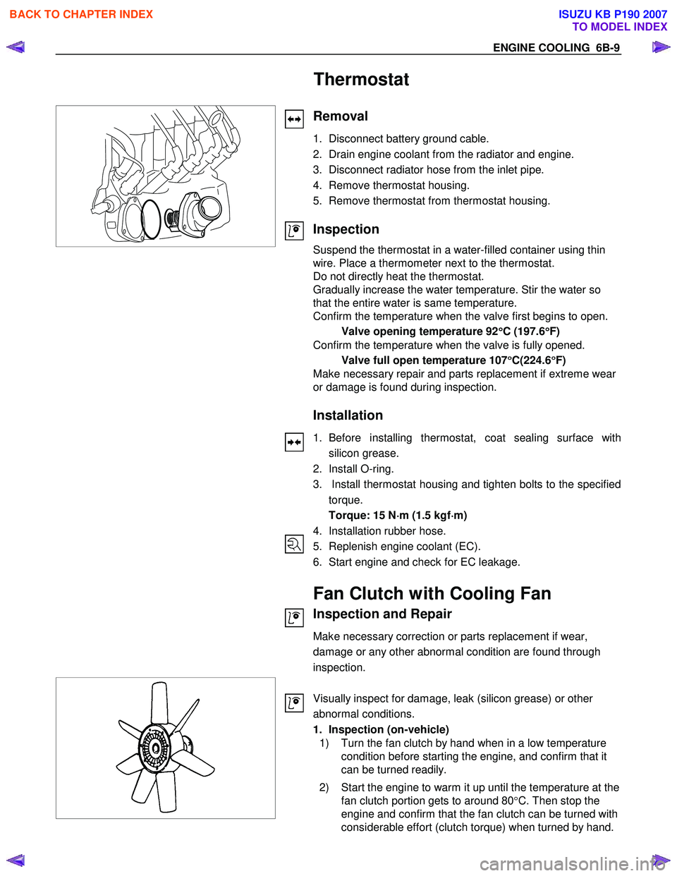
Thermostat
Removal
1. Disconnect battery ground cable.
2. Drain engine coolant from the radiator and engine.
3. Disconnect radiator hose from the inlet pipe.
4. Remove thermostat housing.
5. Remove thermostat from thermostat housing.
Inspection
Suspend the thermostat in a water-filled container using thin
wire. Place a thermometer next to the thermostat.
Do not directly heat the thermostat.
Gradually increase the water temperature. Stir the water so
that the entire water is same temperature.
Confirm the temperature when the valve first begins to open.
Valve opening temperature 92 °
°°
°
C (197.6 °
°°
°
F)
Confirm the temperature when the valve is fully opened.
Valve full open temperature 107 °
°°
°
C(224.6 °
°°
°
F)
Make necessary repair and parts replacement if extreme wear
or damage is found during inspection.
Installation
1. Before installing thermostat, coat sealing surface with
silicon grease.
2. Install O-ring.
3. Install thermostat housing and tighten bolts to the specified torque.
Torque: 15 N ⋅
⋅⋅
⋅
m (1.5 kgf ⋅
⋅⋅
⋅
m)
4. Installation rubber hose.
5. Replenish engine coolant (EC).
6. Start engine and check for EC leakage.
Fan Clutch with Cooling Fan
Inspection and Repair
Make necessary correction or parts replacement if wear,
damage or any other abnormal condition are found through
inspection.
Visually inspect for damage, leak (silicon grease) or other
abnormal conditions.
1. Inspection (on-vehicle)
1) Turn the fan clutch by hand when in a low temperature condition before starting the engine, and confirm that it
can be turned readily.
2) Start the engine to warm it up until the temperature at the fan clutch portion gets to around 80 °C. Then stop the
engine and confirm that the fan clutch can be turned with
considerable effort (clutch torque) when turned by hand.
BACK TO CHAPTER INDEX
TO MODEL INDEX
ISUZU KB P190 2007
Page 2435 of 6020
ENGINE DRIVEABILITY AND EMISSIONS 6E–265
ENGINE COOLANT TEMPERATURE (ECT)
SENSOR
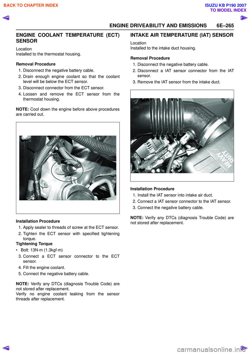
Location
Installed to the thermostat housing.
Removal Procedure 1. Disconnect the negative battery cable.
2. Drain enough engine coolant so that the coolant level will be below the ECT sensor.
3. Disconnect connector from the ECT sensor.
4. Loosen and remove the ECT sensor from the thermostat housing.
NOTE: Cool down the engine before above procedures
are carried out.
Installation Procedure
1. Apply sealer to threads of screw at the ECT sensor.
2. Tighten the ECT sensor with specified tightening torque.
Tightening Torque
• Bolt: 13N·m (1.3kgf·m)
3. Connect a ECT sensor connector to the ECT sensor.
4. Fill the engine coolant.
5. Connect the negative battery cable.
NOTE: Verify any DTCs (diagnosis Trouble Code) are
not stored after replacement.
Verify no engine coolant leaking from the sensor
threads after replacement.
INTAKE AIR TEMPERATURE (IAT) SENSOR
Location
Installed to the intake duct housing.
Removal Procedure 1. Disconnect the negative battery cable.
2. Disconnect a IAT sensor connector from the IAT sensor.
3. Remove the IAT sensor from the intake duct.
Installation Procedure 1. Install the IAT sensor into intake air duct.
2. Connect a IAT sensor connector to the IAT sensor.
3. Connect the negative battery cable.
NOTE: Verify any DTCs (diagnosis Trouble Code) are
not stored after replacement.
BACK TO CHAPTER INDEX
TO MODEL INDEX
ISUZU KB P190 2007