2007 ISUZU KB P190 check engine light
[x] Cancel search: check engine lightPage 979 of 6020

FUEL SYSTEM 6C – 15
140R100037
2. For removal of the quick connector, hold the quick
connector in one hand, and pull out the connector with the
other hand while pressing the square relieve button of the
connector, as illustrated.
NOTE: Do not use tools of any kind. Only use bare hands
when disconnecting the connector. Use a lubricant (light oil)
and/or push and pull the connector until the pipe is
disconnected.
140R100028
Cover the connectors that was removed with a plastic bag,
to prevent dust or rain water from entering.
140R100036
Reuse of Quick–Connector
• Replace the port and connector if scratch, dent or crack is
found.
• Remove any dirt build up on the port when installing the
connector. Replace the connector, if there is any forms o
f
rust, dent, scratch.
• After cleaning the port, insert it straight into the connecto
r
until it clicks. After it clicks, try pulling at 49N (5kgf) it out to
make sure that it is not drawn and is securely locked.
Assembling Advice
By applying engine oil or light oil to the pipe, port makes pipe
assembly easier. The pipe assembly should take place
immediately after applying oil (to prevent dust from sticking to
the pipe surface – which may decrease sealing ability). Test/Inspection After Assembling
1. Reconnect the battery negative cable.
2. Start the engine and observe the engine idle speed. The presence of dirt in the fuel system may affect the fuel
injection system.
3. Check for fuel leakage from the connector.
BACK TO CHAPTER INDEX
TO MODEL INDEX
ISUZU KB P190 2007
Page 1137 of 6020
Engine Control System (4JH1) 6E-103
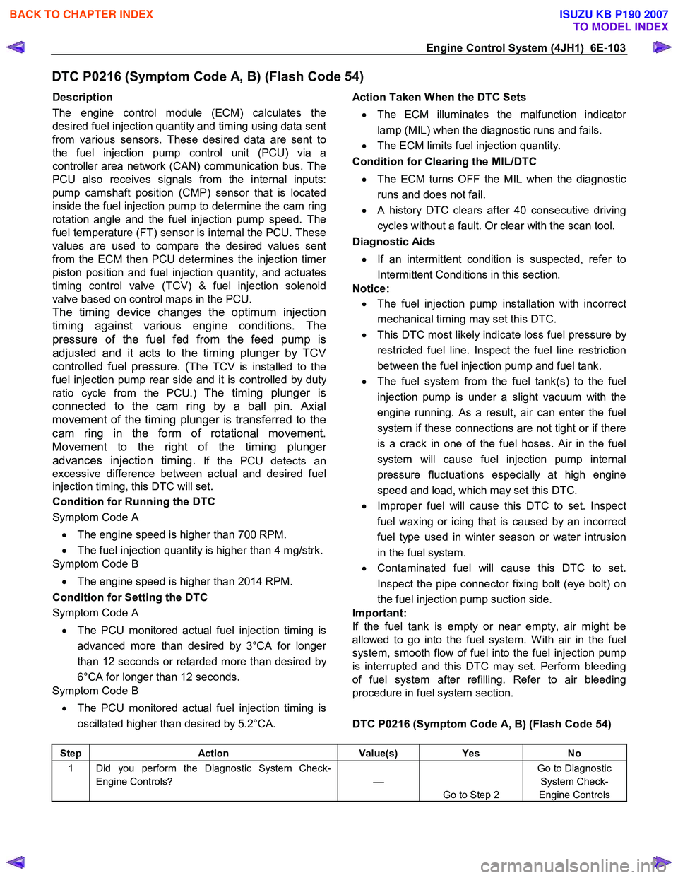
DTC P0216 (Symptom Code A, B) (Flash Code 54)
Description
The engine control module (ECM) calculates the
desired fuel injection quantity and timing using data sent
from various sensors. These desired data are sent to
the fuel injection pump control unit (PCU) via a
controller area network (CAN) communication bus. The
PCU also receives signals from the internal inputs:
pump camshaft position (CMP) sensor that is located
inside the fuel injection pump to determine the cam ring
rotation angle and the fuel injection pump speed. The
fuel temperature (FT) sensor is internal the PCU. These
values are used to compare the desired values sent
from the ECM then PCU determines the injection time
r
piston position and fuel injection quantity, and actuates
timing control valve (TCV) & fuel injection solenoid
valve based on control maps in the PCU.
The timing device changes the optimum injection
timing against various engine conditions. The
pressure of the fuel fed from the feed pump is
adjusted and it acts to the timing plunger by TCV
controlled fuel pressure. (
The TCV is installed to the
fuel injection pump rear side and it is controlled by dut
y
ratio cycle from the PCU.) The timing plunger is
connected to the cam ring by a ball pin. Axial
movement of the timing plunger is transferred to the
cam ring in the form of rotational movement.
Movement to the right of the timing plunge
r
advances injection timing.
If the PCU detects an
excessive difference between actual and desired fuel
injection timing, this DTC will set.
Condition for Running the DTC
Symptom Code A
• The engine speed is higher than 700 RPM.
• The fuel injection quantity is higher than 4 mg/strk.
Symptom Code B
• The engine speed is higher than 2014 RPM.
Condition for Setting the DTC
Symptom Code A
• The PCU monitored actual fuel injection timing is
advanced more than desired by 3°CA for longe
r
than 12 seconds or retarded more than desired by
6°CA for longer than 12 seconds.
Symptom Code B
• The PCU monitored actual fuel injection timing is
oscillated higher than desired by 5.2°CA.
Action Taken When the DTC Sets
• The ECM illuminates the malfunction indicato
r
lamp (MIL) when the diagnostic runs and fails.
• The ECM limits fuel injection quantity.
Condition for Clearing the MIL/DTC
• The ECM turns OFF the MIL when the diagnostic
runs and does not fail.
• A history DTC clears after 40 consecutive driving
cycles without a fault. Or clear with the scan tool.
Diagnostic Aids
• If an intermittent condition is suspected, refer to
Intermittent Conditions in this section.
Notice:
• The fuel injection pump installation with incorrect
mechanical timing may set this DTC.
• This DTC most likely indicate loss fuel pressure by
restricted fuel line. Inspect the fuel line restriction
between the fuel injection pump and fuel tank.
• The fuel system from the fuel tank(s) to the fuel
injection pump is under a slight vacuum with the
engine running. As a result, air can enter the fuel
system if these connections are not tight or if there
is a crack in one of the fuel hoses. Air in the fuel
system will cause fuel injection pump internal
pressure fluctuations especially at high engine
speed and load, which may set this DTC.
• Improper fuel will cause this DTC to set. Inspect
fuel waxing or icing that is caused by an incorrect
fuel type used in winter season or water intrusion
in the fuel system.
• Contaminated fuel will cause this DTC to set.
Inspect the pipe connector fixing bolt (eye bolt) on
the fuel injection pump suction side.
Important:
If the fuel tank is empty or near empty, air might be
allowed to go into the fuel system. W ith air in the fuel
system, smooth flow of fuel into the fuel injection pump
is interrupted and this DTC may set. Perform bleeding
of fuel system after refilling. Refer to air bleeding
procedure in fuel system section.
DTC P0216 (Symptom Code A, B) (Flash Code 54)
Step Action Value(s) Yes No
1 Did you perform the Diagnostic System Check-
Engine Controls?
Go to Step 2 Go to Diagnostic
System Check-
Engine Controls
BACK TO CHAPTER INDEX
TO MODEL INDEX
ISUZU KB P190 2007
Page 1138 of 6020
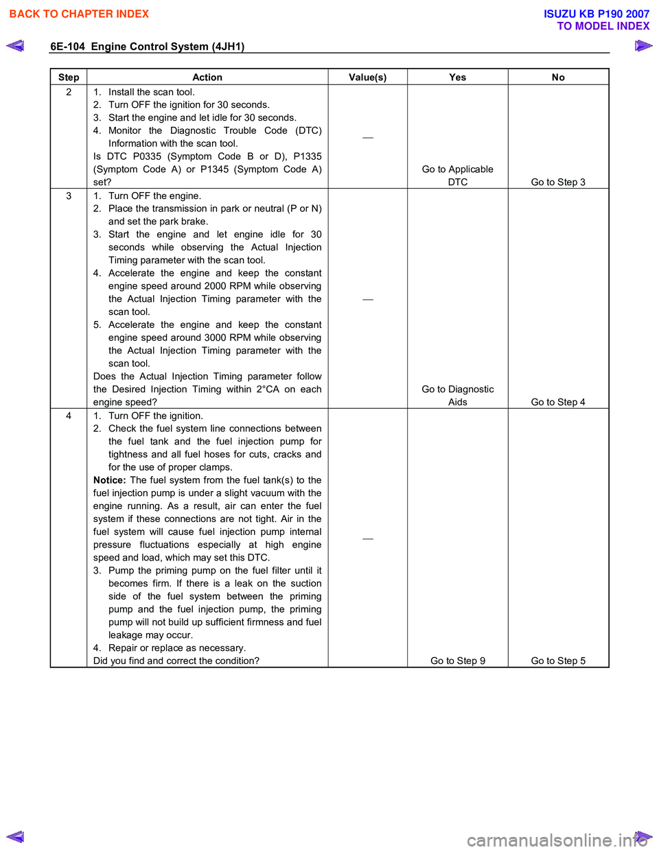
6E-104 Engine Control System (4JH1)
Step Action Value(s) Yes No
2 1. Install the scan tool.
2. Turn OFF the ignition for 30 seconds.
3. Start the engine and let idle for 30 seconds.
4. Monitor the Diagnostic Trouble Code (DTC) Information with the scan tool.
Is DTC P0335 (Symptom Code B or D), P1335
(Symptom Code A) or P1345 (Symptom Code A)
set?
Go to Applicable DTC Go to Step 3
3 1. Turn OFF the engine. 2. Place the transmission in park or neutral (P or N) and set the park brake.
3. Start the engine and let engine idle for 30 seconds while observing the Actual Injection
Timing parameter with the scan tool.
4. Accelerate the engine and keep the constant engine speed around 2000 RPM while observing
the Actual Injection Timing parameter with the
scan tool.
5. Accelerate the engine and keep the constant engine speed around 3000 RPM while observing
the Actual Injection Timing parameter with the
scan tool.
Does the Actual Injection Timing parameter follow
the Desired Injection Timing within 2°CA on each
engine speed?
Go to Diagnostic Aids Go to Step 4
4 1. Turn OFF the ignition. 2. Check the fuel system line connections between the fuel tank and the fuel injection pump for
tightness and all fuel hoses for cuts, cracks and
for the use of proper clamps.
Notice: The fuel system from the fuel tank(s) to the
fuel injection pump is under a slight vacuum with the
engine running. As a result, air can enter the fuel
system if these connections are not tight. Air in the
fuel system will cause fuel injection pump internal
pressure fluctuations especially at high engine
speed and load, which may set this DTC.
3. Pump the priming pump on the fuel filter until it becomes firm. If there is a leak on the suction
side of the fuel system between the priming
pump and the fuel injection pump, the priming
pump will not build up sufficient firmness and fuel
leakage may occur.
4. Repair or replace as necessary.
Did you find and correct the condition?
Go to Step 9 Go to Step 5
BACK TO CHAPTER INDEX
TO MODEL INDEX
ISUZU KB P190 2007
Page 1164 of 6020
6E-130 Engine Control System (4JH1)
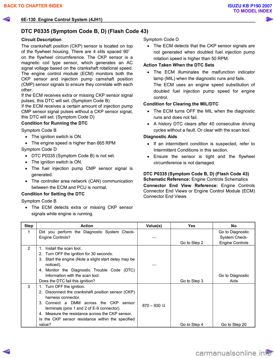
DTC P0335 (Symptom Code B, D) (Flash Code 43)
Circuit Description
The crankshaft position (CKP) sensor is located on top
of the flywheel housing. There are 4 slits spaced 90 °
on the flywheel circumference. The CKP sensor is a
magnetic coil type sensor, which generates an AC
signal voltage based on the crankshaft rotational speed.
The engine control module (ECM) monitors both the
CKP sensor and injection pump camshaft position
(CMP) sensor signals to ensure they correlate with each
other.
If the ECM receives extra or missing CKP sensor signal
pulses, this DTC will set. (Symptom Code B)
If the ECM receives a certain amount of injection pump
CMP sensor signal pulses without a CKP sensor signal,
this DTC will set. (Symptom Code D)
Condition for Running the DTC
Symptom Code B • The ignition switch is ON.
• The engine speed is higher than 665 RPM
Symptom Code D • DTC P0335 (Symptom Code B) is not set.
• The ignition switch is ON.
• The fuel injection pump CMP sensor signal is
generated.
• The controller area network (CAN) communication
between the ECM and PCU is normal.
Condition for Setting the DTC
Symptom Code B • The ECM detects extra or missing CKP senso
r
signals while engine is running.
Symptom Code D
• The ECM detects that the CKP sensor signals are
not generated when doubled fuel injection pump
rotation speed is higher than 50 RPM.
Action Taken When the DTC Sets
• The ECM illuminates the malfunction indicato
r
lamp (MIL) when the diagnostic runs and fails.
The ECM uses an engine speed substitution o
f
doubled fuel injection pump speed for engine
control.
Condition for Clearing the MIL/DTC
• The ECM turns OFF the MIL when the diagnostic
runs and does not fail.
• A history DTC clears after 40 consecutive driving
cycles without a fault. Or clear with the scan tool.
Diagnostic Aids
• If an intermittent condition is suspected, refer to
Intermittent Conditions in this section.
• Ensure the sensor is tight and the flywheel
circumference is not damaged.
DTC P0335 (Symptom Code B, D) (Flash Code 43)
Schematic Reference: Engine Controls Schematics
Connector End View Reference: Engine Controls
Connector End Views or Engine Control Module (ECM)
Connector End Views
Step Action Value(s) Yes No
1 Did you perform the Diagnostic System Check-
Engine Controls?
Go to Step 2 Go to Diagnostic
System Check-
Engine Controls
2 1. Install the scan tool. 2. Turn OFF the ignition for 30 seconds.
3. Start the engine (Note a slight start delay may be noticed).
4. Monitor the Diagnostic Trouble Code (DTC) Information with the scan tool.
Does the DTC fail this ignition?
Go to Step 3 Go to Diagnostic
Aids
3 1. Turn OFF the ignition. 2. Disconnect the crankshaft position sensor (CKP) harness connector.
3. Connect a DMM across the CKP sensor terminals (pins 1 and 2 of E-9 connector).
4. Measure the resistance across the CKP sensor.
Is the CKP sensor resistance within the specified
value? 870 – 930
Ω
Go to Step 4 Go to Step 20
BACK TO CHAPTER INDEX
TO MODEL INDEX
ISUZU KB P190 2007
Page 1170 of 6020
6E-136 Engine Control System (4JH1)
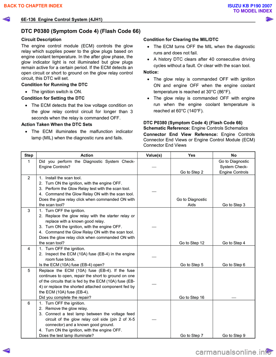
DTC P0380 (Symptom Code 4) (Flash Code 66)
Circuit Description
The engine control module (ECM) controls the glo
w
relay which supplies power to the glow plugs based on
engine coolant temperature. In the after glow phase, the
glow indicator light is not illuminated but glow plugs
remain active for a certain period. If the ECM detects an
open circuit or short to ground on the glow relay control
circuit, this DTC will set.
Condition for Running the DTC
• The ignition switch is ON.
Condition for Setting the DTC
• The ECM detects that the low voltage condition on
the glow relay control circuit for longer than 3
seconds when the relay is commanded OFF.
Action Taken When the DTC Sets
• The ECM illuminates the malfunction indicato
r
lamp (MIL) when the diagnostic runs and fails.
Condition for Clearing the MIL/DTC
• The ECM turns OFF the MIL when the diagnostic
runs and does not fail.
• A history DTC clears after 40 consecutive driving
cycles without a fault. Or clear with the scan tool.
Notice:
• The glow relay is commanded OFF with ignition
ON and engine OFF when the engine coolant
temperature is reached at 30°C (86°F).
• The glow relay is commanded OFF with engine
run when the engine coolant temperature is
reached at 60°C (140°F).
DTC P0380 (Symptom Code 4) (Flash Code 66)
Schematic Reference: Engine Controls Schematics
Connector End View Reference: Engine Controls
Connector End Views or Engine Control Module (ECM)
Connector End Views
Step Action Value(s) Yes No
1 Did you perform the Diagnostic System Check-
Engine Controls?
Go to Step 2 Go to Diagnostic
System Check-
Engine Controls
2 1. Install the scan tool. 2. Turn ON the ignition, with the engine OFF.
3. Perform the Glow Relay test with the scan tool.
4. Command the Glow Relay ON with the scan tool.
Does the glow relay click when commanded ON with
the scan tool?
Go to Diagnostic Aids Go to Step 3
3 1. Turn OFF the ignition. 2. Replace the glow relay with the starter relay or replace with a known good relay.
3. Turn ON the ignition, with the engine OFF.
4. Command the Glow Relay ON with the scan tool.
Does the glow relay click when commanded ON with
the scan tool?
Go to Step 12 Go to Step 4
4 1. Turn OFF the ignition. 2. Inspect the ECM (10A) fuse (EB-4) in the engine room fuse block.
Is the ECM (10A) fuse (EB-4) open?
Go to Step 5 Go to Step 6
5 Replace the ECM (10A) fuse (EB-4). If the fuse continues to open, repair the short to ground on one
of the circuits that is fed by the ECM (10A) fuse (EB-
4) or replace the shorted attached component fed by
the ECM (10A) fuse (EB-4).
Did you complete the repair?
Go to Step 16
6 1. Turn OFF the ignition.
2. Remove the glow relay.
3. Connect a test lamp between the voltage feed circuit of the glow relay coil side (pin 2 of X-5
connector) and a known good ground.
4. Turn ON the ignition, with the engine OFF.
Does the test lamp illuminate?
Go to Step 7 Go to Step 9
BACK TO CHAPTER INDEX
TO MODEL INDEX
ISUZU KB P190 2007
Page 1173 of 6020
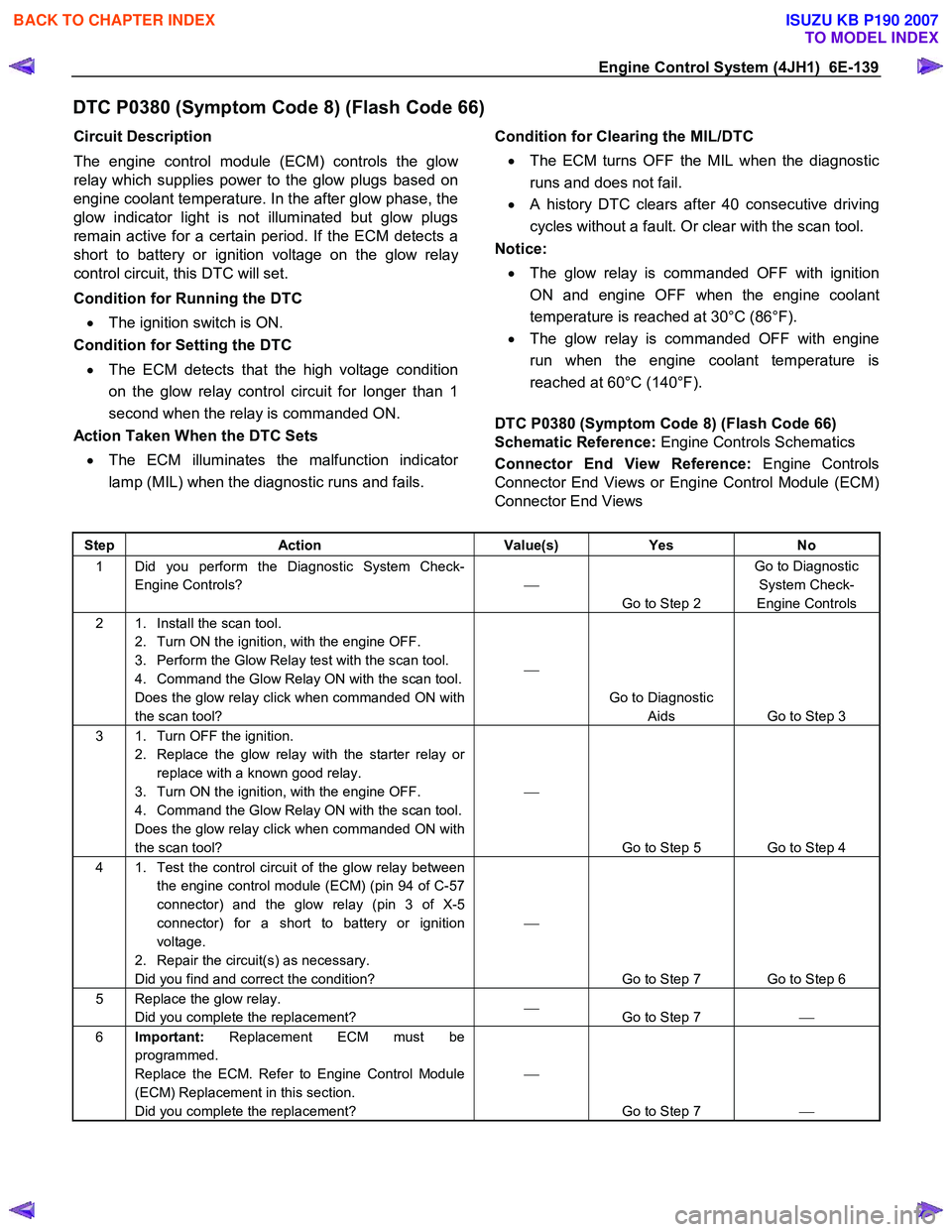
Engine Control System (4JH1) 6E-139
DTC P0380 (Symptom Code 8) (Flash Code 66)
Circuit Description
The engine control module (ECM) controls the glo
w
relay which supplies power to the glow plugs based on
engine coolant temperature. In the after glow phase, the
glow indicator light is not illuminated but glow plugs
remain active for a certain period. If the ECM detects a
short to battery or ignition voltage on the glow rela
y
control circuit, this DTC will set.
Condition for Running the DTC
• The ignition switch is ON.
Condition for Setting the DTC
• The ECM detects that the high voltage condition
on the glow relay control circuit for longer than 1
second when the relay is commanded ON.
Action Taken When the DTC Sets
• The ECM illuminates the malfunction indicato
r
lamp (MIL) when the diagnostic runs and fails.
Condition for Clearing the MIL/DTC
• The ECM turns OFF the MIL when the diagnostic
runs and does not fail.
• A history DTC clears after 40 consecutive driving
cycles without a fault. Or clear with the scan tool.
Notice:
• The glow relay is commanded OFF with ignition
ON and engine OFF when the engine coolant
temperature is reached at 30°C (86°F).
• The glow relay is commanded OFF with engine
run when the engine coolant temperature is
reached at 60°C (140°F).
DTC P0380 (Symptom Code 8) (Flash Code 66)
Schematic Reference: Engine Controls Schematics
Connector End View Reference: Engine Controls
Connector End Views or Engine Control Module (ECM)
Connector End Views
Step Action Value(s) Yes No
1 Did you perform the Diagnostic System Check-
Engine Controls?
Go to Step 2 Go to Diagnostic
System Check-
Engine Controls
2 1. Install the scan tool. 2. Turn ON the ignition, with the engine OFF.
3. Perform the Glow Relay test with the scan tool.
4. Command the Glow Relay ON with the scan tool.
Does the glow relay click when commanded ON with
the scan tool?
Go to Diagnostic Aids Go to Step 3
3 1. Turn OFF the ignition. 2. Replace the glow relay with the starter relay or replace with a known good relay.
3. Turn ON the ignition, with the engine OFF.
4. Command the Glow Relay ON with the scan tool.
Does the glow relay click when commanded ON with
the scan tool?
Go to Step 5 Go to Step 4
4 1. Test the control circuit of the glow relay between the engine control module (ECM) (pin 94 of C-57
connector) and the glow relay (pin 3 of X-5
connector) for a short to battery or ignition
voltage.
2. Repair the circuit(s) as necessary.
Did you find and correct the condition?
Go to Step 7 Go to Step 6
5 Replace the glow relay. Did you complete the replacement?
Go to Step 7
6 Important: Replacement ECM must be
programmed.
Replace the ECM. Refer to Engine Control Module
(ECM) Replacement in this section.
Did you complete the replacement?
Go to Step 7
BACK TO CHAPTER INDEX
TO MODEL INDEX
ISUZU KB P190 2007
Page 1201 of 6020
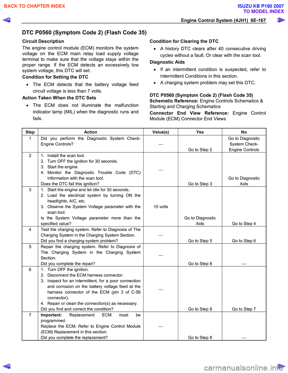
Engine Control System (4JH1) 6E-167
DTC P0560 (Symptom Code 2) (Flash Code 35)
Circuit Description
The engine control module (ECM) monitors the system
voltage on the ECM main relay load supply voltage
terminal to make sure that the voltage stays within the
proper range. If the ECM detects an excessively lo
w
system voltage, this DTC will set.
Condition for Setting the DTC
• The ECM detects that the battery voltage feed
circuit voltage is less than 7 volts.
Action Taken When the DTC Sets
• The ECM does not illuminate the malfunction
indicator lamp (MIL) when the diagnostic runs and
fails.
Condition for Clearing the DTC
• A history DTC clears after 40 consecutive driving
cycles without a fault. Or clear with the scan tool.
Diagnostic Aids
• If an intermittent condition is suspected, refer to
Intermittent Conditions in this section.
• A charging system problem may set this DTC.
DTC P0560 (Symptom Code 2) (Flash Code 35)
Schematic Reference: Engine Controls Schematics &
Starting and Charging Schematics
Connector End View Reference: Engine Control
Module (ECM) Connector End Views
Step Action Value(s) Yes No
1 Did you perform the Diagnostic System Check-
Engine Controls?
Go to Step 2 Go to Diagnostic
System Check-
Engine Controls
2 1. Install the scan tool. 2. Turn OFF the ignition for 30 seconds.
3. Start the engine.
4. Monitor the Diagnostic Trouble Code (DTC) Information with the scan tool.
Does the DTC fail this ignition?
Go to Step 3 Go to Diagnostic
Aids
3 1. Start the engine and let idle for 30 seconds. 2. Load the electrical system by turning ON the headlights, A/C, etc.
3. Observe the System Voltage parameter with the scan tool.
Is the System Voltage parameter more than the
specified value? 10 volts
Go to Diagnostic Aids Go to Step 4
4 Test the charging system. Refer to Diagnosis of The Charging System in the Charging System Section.
Did you find a charging system problem?
Go to Step 5 Go to Step 6
5 Repair the charging system. Refer to Diagnosis of The Charging System in the Charging System
Section.
Did you complete the repair?
Go to Step 8
6 1. Turn OFF the ignition.
2. Disconnect the ECM harness connector.
3. Inspect for an intermittent, for a poor connection and corrosion on the battery voltage feed at the
harness connector of the ECM (pin 3 of C-56
connector).
4. Repair or clean the connection(s) as necessary.
Did you find and correct the condition?
Go to Step 8 Go to Step 7
7 Important: Replacement ECM must be
programmed.
Replace the ECM. Refer to Engine Control Module
(ECM) Replacement in this section.
Did you complete the replacement?
Go to Step 8
BACK TO CHAPTER INDEX
TO MODEL INDEX
ISUZU KB P190 2007
Page 1215 of 6020
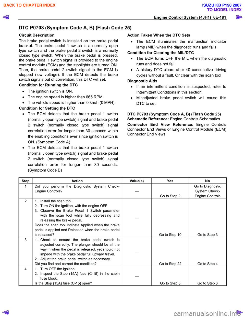
Engine Control System (4JH1) 6E-181
DTC P0703 (Symptom Code A, B) (Flash Code 25)
Circuit Description
The brake pedal switch is installed on the brake pedal
bracket. The brake pedal 1 switch is a normally open
type switch and the brake pedal 2 switch is a normally
closed type switch. W hen the brake pedal is pressed,
the brake pedal 1 switch signal is provided to the engine
control module (ECM) and the stoplights are turned ON.
Then, the brake pedal 2 switch signal to the ECM is
stopped (low voltage). If the ECM detects the brake
switch signals out of correlation, this DTC will set.
Condition for Running the DTC
• The ignition switch is ON.
• The engine speed is higher than 665 RPM.
• The vehicle speed is higher than 0 km/h (0 MPH).
Condition for Setting the DTC • The ECM detects that the brake pedal 1 switch
(normally open type switch) signal and brake pedal
2 switch (normally closed type switch) signal
correlation error for longer than 30 seconds within
the enabling conditions ever since ignition switch is
ON. (Symptom Code A)
• The ECM detects that the brake pedal 1 switch
(normally open type switch) signal and brake pedal
2 switch (normally closed type switch) signal
correlation error for longer than 30 seconds.
(Symptom Code B)
Action Taken When the DTC Sets
• The ECM illuminates the malfunction indicato
r
lamp (MIL) when the diagnostic runs and fails.
Condition for Clearing the MIL/DTC • The ECM turns OFF the MIL when the diagnostic
runs and does not fail.
• A history DTC clears after 40 consecutive driving
cycles without a fault. Or clear with the scan tool
Diagnostic Aids • If an intermittent condition is suspected, refer to
Intermittent Conditions in this section.
• Misadjusted brake pedal switch will cause this
DTC to set.
DTC P0703 (Symptom Code A, B) (Flash Code 25)
Schematic Reference: Engine Controls Schematics
Connector End View Reference: Engine Controls
Connector End Views or Engine Control Module (ECM)
Connector End Views
Step Action Value(s) Yes No
1 Did you perform the Diagnostic System Check-
Engine Controls?
Go to Step 2 Go to Diagnostic
System Check-
Engine Controls
2 1. Install the scan tool. 2. Turn ON the ignition, with the engine OFF.
3. Observe the Brake Pedal 1 Switch parameter with the scan tool while fully depressing and
releasing the brake pedal.
Does the scan tool indicate Applied when the brake
pedal is applied and Released when the brake pedal
is released?
Go to Step 10 Go to Step 3
3 1. Check to ensure the brake pedal switch is adjusted correctly. The plunger should be all the
way in when the pedal is released, yet should not
impede with the brake pedal full upward travel.
2. Adjust the brake pedal switch as necessary.
Did you find and correct the condition?
Go to Step 22 Go to Step 4
4 1. Turn OFF the ignition. 2. Inspect the Stop (15A) fuse (C-15) in the cabin fuse block.
Is the Stop (15A) fuse (C-15) open?
Go to Step 5 Go to Step 6
BACK TO CHAPTER INDEX
TO MODEL INDEX
ISUZU KB P190 2007