Page 4144 of 6020
UNIT REPAIR (AW30–40LE) 7A4–9
8. Remove the accumulator piston (B–2).
9. Remove the accumulator piston (C –2).
Remove accumulator pistons and springs from
transmission case.
240RY00010
10. Applying compressed air to the oil hole, remove the B–0 accumulator piston and spring.
240RY00011
11. Remove the C –0 accumulator piston.
240RY00012
12. Remove the second brake drum gasket.
13. Remove the solenoid wiring.
Turn over transmission, remove the solenoid
wiring stopper plate from the case.
Pull the wiring out of the transmission case.
14. Remove the snap ring, rotor and key (4 ×4).
Remove the snap ring from the output shaft.
Remove the rotor and key.
247R200002
15. Remove the snap ring, speedometer sensor drive
gear and ball (4 ×2).
Remove the snap ring from the output shaft.
Remove the speedometer sensor drive gear, and
ball.
BACK TO CHAPTER INDEX
TO MODEL INDEX
ISUZU KB P190 2007
Page 4145 of 6020
7A4–10 UNIT REPAIR (AW30–40LE)
16. Remove the spacer, rotor, key and snap ring (4×2).
Remove the spacer, rotor and key.
Remove the snap ring from the output shaft.
247L100001
Reassembly
1. Install the converter housing.
Torque:
M10 – 34 N ·m (3.5 kgf ·m/25 lb ·ft)
M12 – 57 N ·m (5.8 kgf ·m/42 lb ·ft)
240R200022
2. Install the snap ring, key and rotor (4 ×2).
Install the snap ring to the output shaft.
Install the key and rotor. 3. Install the spacer, ball, speedometer sensor drive
gear and snap ring (4 ×2).
Install the spacer, ball and speedometer sensor
drive gear.
Install the snap ring to the output shaft.
247L100001
4. Install the key, rotor and snap ring (4 ×4).
Install the key and rotor.
Install the snap ring to the output shaft.
247R200002
BACK TO CHAPTER INDEX
TO MODEL INDEX
ISUZU KB P190 2007
Page 4572 of 6020
7B-8 MSG MODEL
Exhaust Pipe
1. Remove the exhaust pipe bracket from the transmission
case.
2. Remove the exhaust pipe.
Rear Propeller Shaft (Dual Shaft Type)
1. Apply setting marks to the 2nd propeller shaft flange yoke.
This will prevent mispositioning during the installation procedure.
2. Remove the 2nd propeller shaft flange yoke nuts at the drive pinion side
1.
3. Remove the center bearing retainer bolts
2 .
4. Remove the 1st propeller shaft with the center bearing and the 2nd propeller shaft.
Pull the 1st propeller shaft toward the rear of the vehicle until the spline yoke is free of the transmission main shaft.
Harness Connector
Disconnect the back up light switch connector and the
speedometer sensor connector.
Slave Cylinder
Remove the slave cylinder from the transmission case.
BACK TO CHAPTER INDEX
TO MODEL INDEX
ISUZU KB P190 2007
Page 4577 of 6020

MSG MODEL 7B-13
Starter Motor
1. Install the starter motor to the engine rear plate.
2. Tighten the starter motor bolts to the specified torque.
Starter Motor Torque N⋅m (kgf ⋅m/lb ⋅ft)
78 (8.0 / 58)
Slave Cylinder
Install the slave cylinder to the transmission case.
Slave Cylinder Bolt Torque N ⋅m (kgf ⋅m/lb ⋅ft
)
78 (8.0 / 58)
Harness Connector
Connect the back up light switch connector and speedometer
sensor connector.
Rear Propeller Shaft (Dual Shaft Type)
1. Place the center bearing and retainer 1 together with the
1st propeller shaft
2 and 2nd propeller shaft 7on the No.4
crossmember
3.
2. Insert the splined yoke
4 into the transmission main shaft
spline
5.
3. Tighten the center bearing retainer bolts
6 to the specified
torque.
Center Bearing Retainer Bolt Torque N ⋅m (kgf ⋅m/lb ⋅ft)
61 (6.2 / 45)
4. Connect the 2nd propeller shaft
7 and drive pinion side 8.
Be sure to align the setting marks applied at disassembly.
5. Tighten the coupling bolts to the specified torque.
Propeller Shaft Flange Yoke Bolt
Torque N ⋅m (kgf ⋅m/lb ⋅ft)
M8 : 35 (3.6 / 26)
M10 : 63 (6.4 / 46)
Exhaust Pipe
1. Install the exhaust pipe to the exhaust manifold and the 2nd
exhaust pipe.
2. Install the exhaust pipe bracket to the transmission case.
BACK TO CHAPTER INDEX
TO MODEL INDEX
ISUZU KB P190 2007
Page 4579 of 6020
MSG MODEL 7B-15
DISASSEMBLY
MAJOR COMPONENTS
RTW 47BLF000301
Disassembly Steps
1. Clutch shift block and release bearing
2. Clutch shift fork
3. Speedometer sensor
4. Speedometer driven gear assembly
5. Gear control box assembly
� 6. Front cover with oil seal
� 7. Counter gear snap ring
� 8. Bearing snap ring
9. Rear cover with oil seal
10. Transmission case
11. Intermediate plate with gear assembly
BACK TO CHAPTER INDEX
TO MODEL INDEX
ISUZU KB P190 2007
Page 4584 of 6020
7B-20 MSG MODEL
REVERSE GEAR AND 5TH GEAR
Disassembly Steps
1. Bearing snap ring
2. Speedometer drive gear and lock ball
3. Bearing spacer
4. Mainshaft end ball bearing
5. Thrust ring snap ring
6. Thrust washer thrust ring
7. Thrust washer and lock ball
8. Counter reverse gear nut and washer
� 9. Counter end ball bearing
� 10. Counter 5th gear
11. Counter reverse gear
12. 5th gear
13. 5th block ring
14. Needle bearing
� 15. Mainshaft lock nut and washer
� 16. Rev. - 5th synchronizer assembly
17. Reverse gear
18. Needle bearing
19. Needle bearing collar
20. Thrust washer
21. Counter reverse gear lock nut
22. Thrust washer
23. Reverse idler gear
24. Thrust washer
25. Reverse idler shaft
� 26. Bearing snap ring
� 27. Bearing snap ring
� 28. Intermediate plate
BACK TO CHAPTER INDEX
TO MODEL INDEX
ISUZU KB P190 2007
Page 4598 of 6020
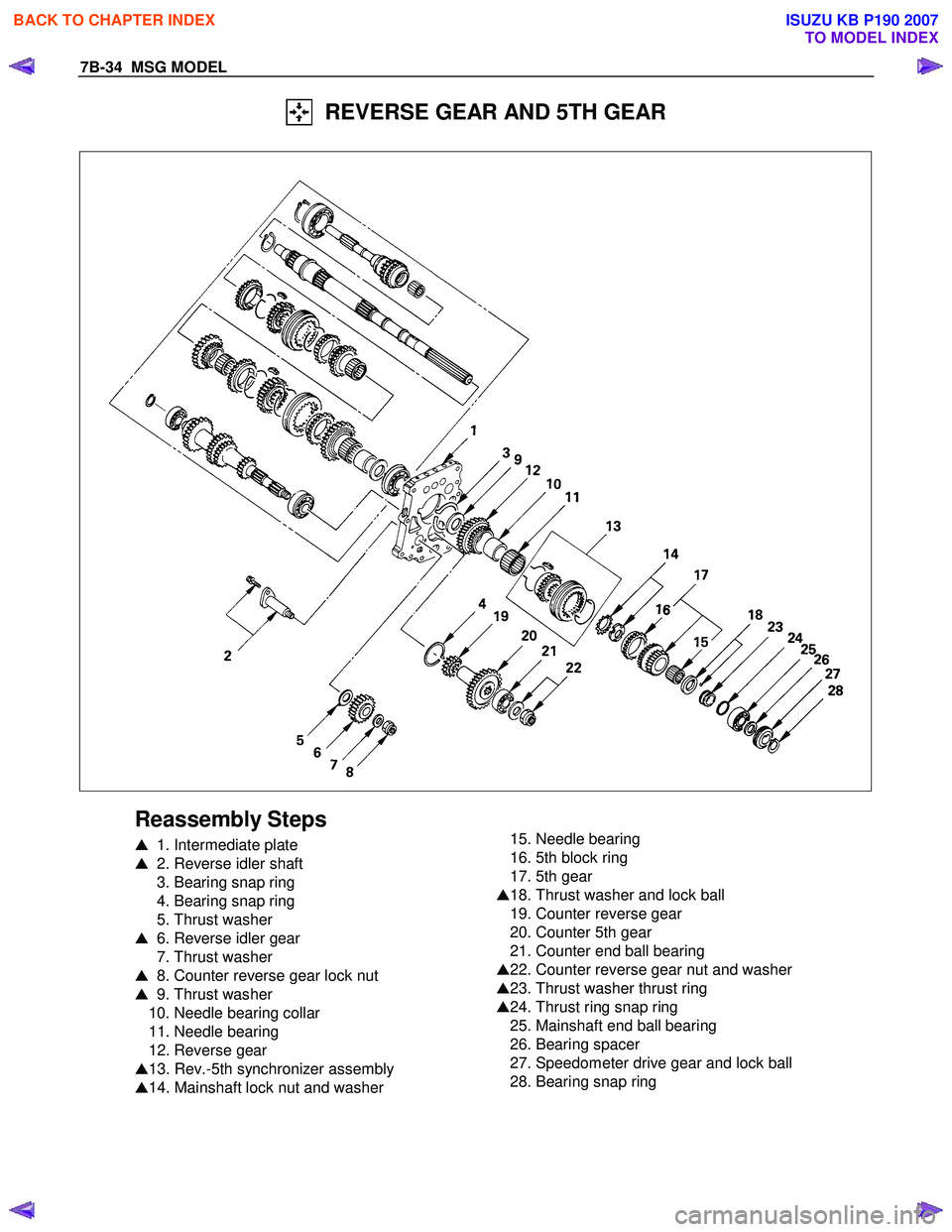
7B-34 MSG MODEL
REVERSE GEAR AND 5TH GEAR
Reassembly Steps
� 1. Intermediate plate
� 2. Reverse idler shaft
3. Bearing snap ring
4. Bearing snap ring
5. Thrust washer
� 6. Reverse idler gear
7. Thrust washer
� 8. Counter reverse gear lock nut
� 9. Thrust washer
10. Needle bearing collar
11. Needle bearing
12. Reverse gear
� 13. Rev.-5th synchronizer assembly
� 14. Mainshaft lock nut and washer
15. Needle bearing
16. 5th block ring
17. 5th gear
� 18. Thrust washer and lock ball
19. Counter reverse gear
20. Counter 5th gear
21. Counter end ball bearing
� 22. Counter reverse gear nut and washer
� 23. Thrust washer thrust ring
� 24. Thrust ring snap ring
25. Mainshaft end ball bearing
26. Bearing spacer
27. Speedometer drive gear and lock ball
28. Bearing snap ring
BACK TO CHAPTER INDEX
TO MODEL INDEX
ISUZU KB P190 2007
Page 4604 of 6020
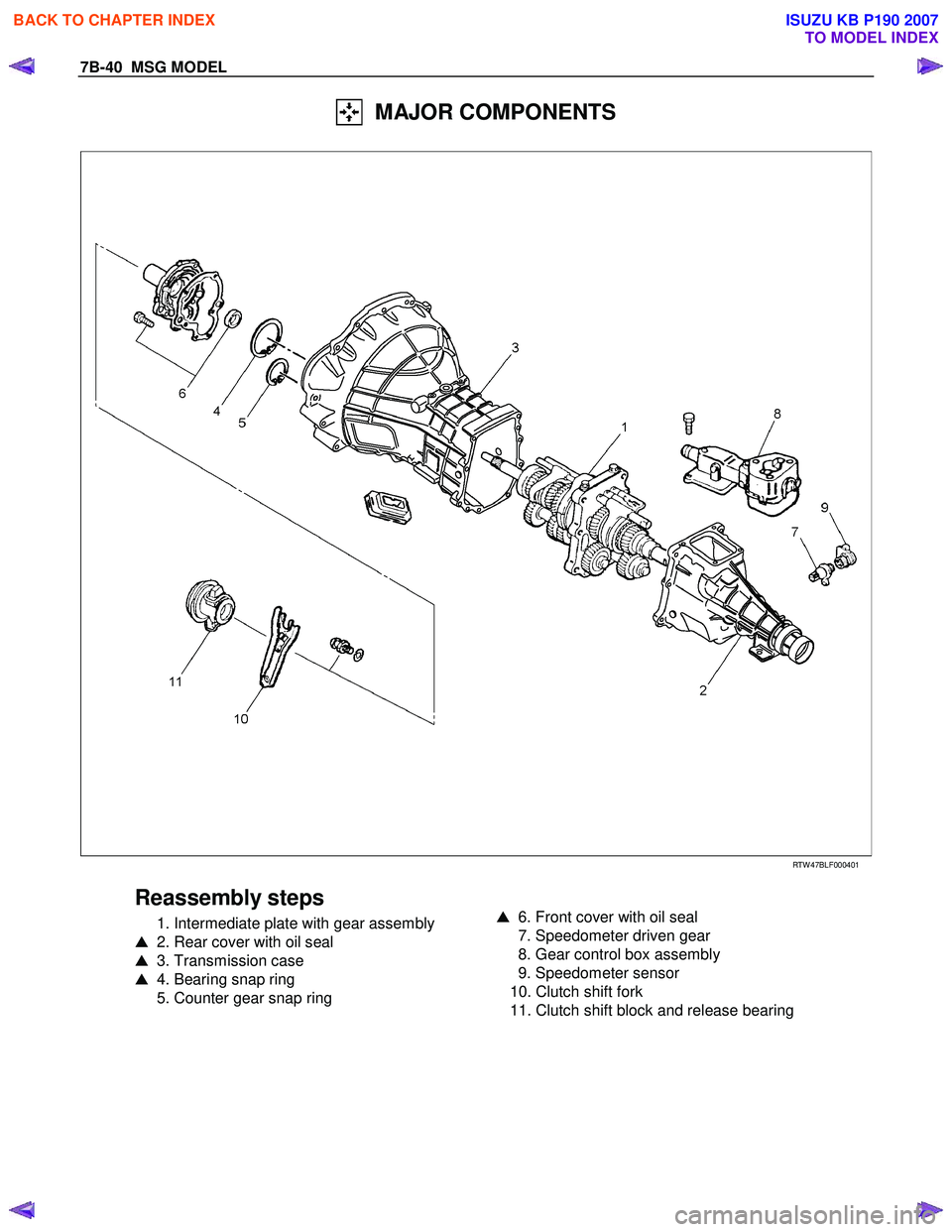
7B-40 MSG MODEL
MAJOR COMPONENTS
RTW 47BLF000401
Reassembly steps
1. Intermediate plate with gear assembly
� 2. Rear cover with oil seal
� 3. Transmission case
� 4. Bearing snap ring
5. Counter gear snap ring
� 6. Front cover with oil seal
7. Speedometer driven gear
8. Gear control box assembly
9. Speedometer sensor
10. Clutch shift fork
11. Clutch shift block and release bearing
BACK TO CHAPTER INDEX
TO MODEL INDEX
ISUZU KB P190 2007
 7A4–9
8. Remove the accumulator piston (B–2).
9. Remove the accumulator piston (C –2).
Remove accumulator pistons and springs from
transmission case.
240RY00010
10.")

16. Remove the spacer, rotor, key and snap ring (4×2).
Remove the spacer, rotor and key.
Remove the snap ring from the output shaft.
247L100001
Reassembly
1. In")

1. Apply setting")