Page 1627 of 6020
6E-10 ENGINE CONTROL SYSTEM (4JK1/4JJ1)
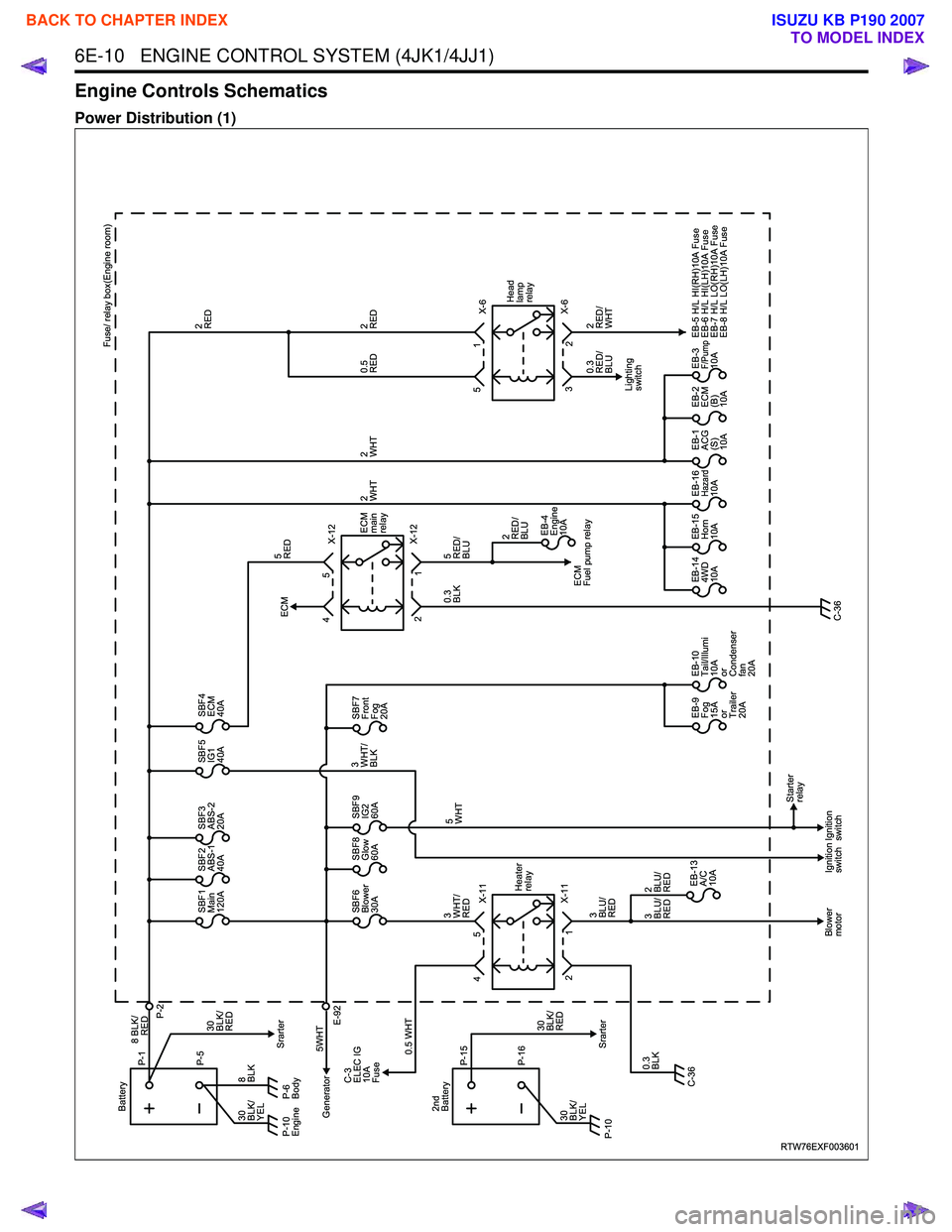
Engine Controls Schematics
Power Distribution (1)
RTW76EXF003601
X-11
X-11 Heater
relay
1
2
Blower
motor Ignition
switchIgnition
switch Starter
relay
SBF1
Main
120A SBF2
ABS-1
40A SBF3
ABS-2
20A SBF5
IG1
40A SBF4
ECM
40A
SBF6
Blower
30A
EB-13�
A/C
10A
2�
BLU/
RED
3�
BLU/
RED 3�
BLU/
RED SBF8
Glow
60A
SBF7
Front
Fog
20A
SBF9
IG2
60A
EB-9�
Fog
15A
or
Trailer
20AEB-10�
Tail/Illumi
10A
or
Condenser
fan
20A EB-4
Engine
10A
EB-14�
4WD
10A EB-15�
Horn
10A EB-16�
Hazard10A EB-1�
ACG
(S)
10AEB-2�
ECM
(B)
10AEB-3�
F/Pump10A
EB-5 H/L HI(RH)10A Fuse
EB-6 H/L HI(LH)10A Fuse
EB-7 H/L LO(RH)10A Fuse
EB-8 H/L LO(LH)10A Fuse
P-6
Body
Generator P-5
8 BLK/
P-1
P-2
Battery
8�
BLK 5WHTSrarter
Srarter
C-3
ELEC IG
10A
Fuse
E-92
0.5 WHT
0.3�
BLK 3�
WHT/
RED 5�
WHT
0.3�
BLK 5�
RED/
BLU
5�
RED
3�
WHT/
BLK
30�
BLK/
RED
30�
BLK/
YEL
P-10�
Engine
5
4 X-12
X-12
ECM
Fuel pump relay
ECM
ECM
main
relay
1
2 5
4
X-6
X-6
2�
RED/
WHT
0.3
RED/
BLU Fuse/ relay box(Engine room)
2�
RED
2�
RED
0.5�
RED
2�
WHT
2�
RED/
BLU 2�
WHT
2
3 1
5
Lighting
switch Head
lamp
relay
C-36 C-36
RED
P-16
P-15
2nd
Battery
30�
BLK/
YEL 30�
BLK/
RED
P-10�
BACK TO CHAPTER INDEX
TO MODEL INDEX
ISUZU KB P190 2007
Page 3198 of 6020
Engine Cooling – V6 Engine Page 6B1–63
4.5 Problems Not Requiring Disassembly of
Cooling System
1 Large obstructions blocking radiator or condenser airflow.
• Auxiliary oil coolers
• License plate
• Obstruction of radiator grille, for example, driving lights or mud
2 Loose, damaged or missing air chute side panels.
3 Missing or damaged air baffle.
4 Cracked or loose coolant recovery system hose.
5 Leaking heater component such as the heater core or water valve.
4.6 Problems Requiring Disassembly of Cooling System
1 Damaged cooling fan or faulty motor operation.
2 Pressure test cooling system.
3 Defective coolant pump.
• Eroded or broken impeller vanes
• Failed bearing or seal – check for shaft or bearing end play
4 Internally blocked radiator core.
5 Obstruction of coolant recovery system.
6 Internal system leaks.
• Head gaskets
• Cracked cylinder block
• Engine front cover
• Intake manifold gaskets
7 Blocked coolant passages in cylinder heads or block – remove cylinder heads and check.
4.7 Black Light and Dye Leak Diagnosis Method
It is strongly recommended that this diagnostic method be used to diagnose fluid leaks. This method is a proven and
reliable method that identifies the specific leak source.
The black light kit can be used for the leak detection of a number of fluids, when used with the appropriate tracer dye.
Examples are: Coolant, Engine Oil, Automatic Transmission Fluid and Air Conditioning Refrigerant (R134A).
The following is a summary of the steps involved in detecting a cooling system fluid leak using black light and dye:
1 Pour specified amount of dye into the cooling system via the coolant filler cap on the outlet housing. Refer 3.1 Service Notes in this Section.
2 Road test the vehicle under normal operating conditions.
3 Direct the light towards the suspect area. The fluid leak will appear as a brightly coloured path leading from the source.
4 Repair fluid leak and recheck to ensure that leak has been rectified.
5 Refer to the manufacturer’s directions when using this method.
BACK TO CHAPTER INDEX
TO MODEL INDEX
ISUZU KB P190 2007
Page 5550 of 6020
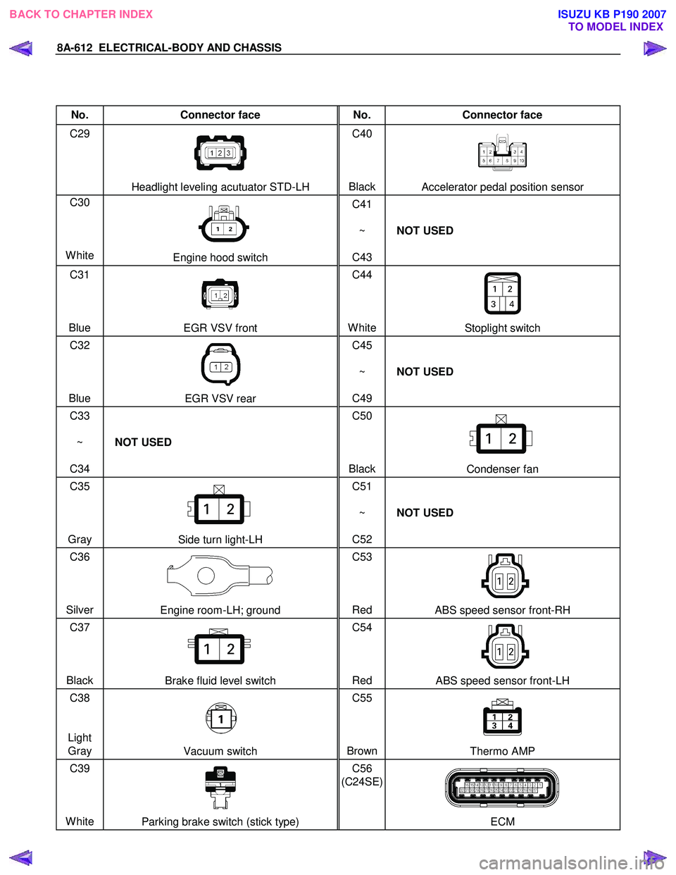
8A-612 ELECTRICAL-BODY AND CHASSIS
No. Connector face No. Connector face
C29
Headlight leveling acutuator STD-LH C40
BlackAccelerator pedal position sensor
C30
White
Engine hood switch C41
~
C43 NOT USED
C31
Blue
EGR VSV front C44
WhiteStoplight switch
C32
Blue
EGR VSV rear C45
~
C49 NOT USED
C33
~
C34 NOT USED C50
Black
Condenser fan
C35
Gray
Side turn light-LH C51
~
C52 NOT USED
C36
Silver
Engine room-LH; ground C53
Red ABS speed sensor front-RH
C37
Black
Brake fluid level switch C54
Red ABS speed sensor front-LH
C38
Light Gray
Vacuum switch C55
BrownThermo AMP
C39
White
Parking brake switch (stick type) C56
(C24SE)
ECM
BACK TO CHAPTER INDEX TO MODEL INDEXISUZU KB P190 2007
Page 5571 of 6020
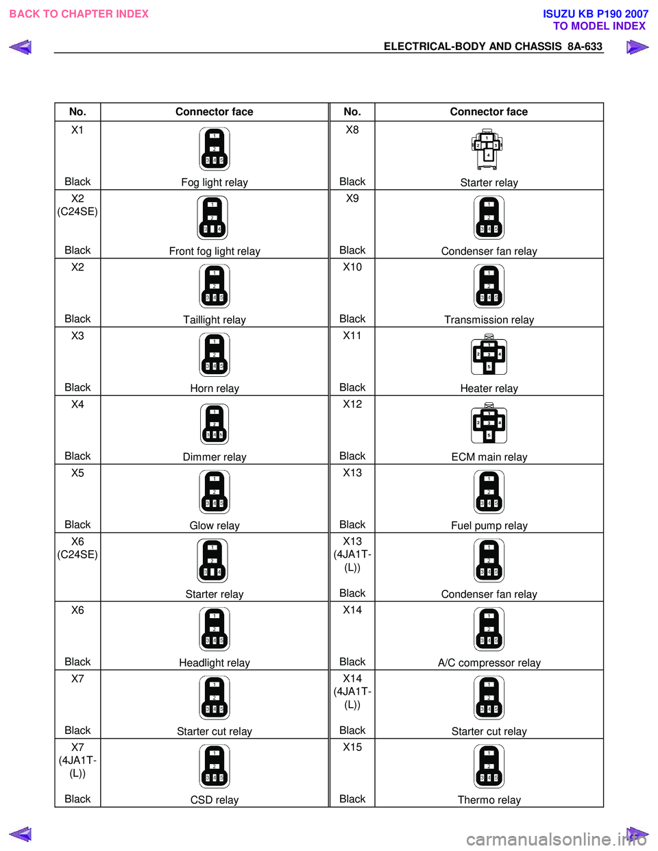
ELECTRICAL-BODY AND CHASSIS 8A-633
No. Connector face No. Connector face
X1
Black
Fog light relay X8
BlackStarter relay
X2
(C24SE)
Black
Front fog light relay X9
BlackCondenser fan relay
X2
Black
Taillight relay X10
BlackTransmission relay
X3
Black
Horn relay X11
BlackHeater relay
X4
Black
Dimmer relay X12
BlackECM main relay
X5
Black
Glow relay X13
BlackFuel pump relay
X6
(C24SE)
Starter relay X13
(4JA1T- (L))
BlackCondenser fan relay
X6
Black
Headlight relay X14
BlackA/C compressor relay
X7
Black
Starter cut relay X14
(4JA1T- (L))
BlackStarter cut relay
X7
(4JA1T- (L))
Black
CSD relay X15
BlackThermo relay
BACK TO CHAPTER INDEX TO MODEL INDEXISUZU KB P190 2007
Page:
< prev 1-8 9-16 17-24