2007 ISUZU KB P190 check oil
[x] Cancel search: check oilPage 2519 of 6020
Engine Mechanical – V6 Page 6A1–40
Cause Correction
W orn valve guides and or valve stems. Inspect and repair valves and valve guides as required,
refer to 3.22 Cylinder Head Assembly.
W orn or damaged valve stem oil seal. Replace valve stem oil seals as required, refer to 3.22
Cylinder Head Assembly.
Piston rings broken, worn or not seated correctly. Allowing adequate time for the piston rings to seat correctly,
replace piston rings as required, refer to 4.5 Pistons, Pins,
Rings, Connecting Rods and Big-end Bearings.
Piston rings incorrectly installed or not matched to cylinder
bore oversize. Replace piston rings as required, refer to 4.5 Pistons, Pins,
Rings, Connecting Rods and Big-end Bearings.
2.18 Engine Oil Leak Diagnosis
Introduction
It is important to correctly identify the source of an engine oil leak. For example, a power steering fluid leak or spillage
during servicing can travel across the valley area of the engine and run-out the weep hole, which is located at the back of
the cylinder block. Failure to correctly identify the source of an engine oil leak can lead to unnecessary replacement of
engine components.
Most fluid leaks can be repaired by repairing or replacing the faulty component or resealing the gasket surface. However,
once a leak is identified it is important to determine and repair the cause as well as the leak itself.
Locating and Identifying the Leak
Inspect the leaking fluid and determine whether it is engine oil, transmission fluid, power steering fluid, brake fluid or
some other fluid. If unsure of the source of the leaking lubricant, a quick check of fluid levels should indicate where the
fluid is coming from, as one or more fluid level should be low.
Visual Inspection
Once the type of leaking fluid has been determined, a visual inspection of the affected system should be performed.
W hen performing the visual inspection:
1 Bring the vehicle to the normal operating temperature.
2 Park the vehicle over a large sheet of paper or other clean surface.
3 Leave the vehicle idling for 2-3 minutes, then check for dripping fluid.
4 If required, identify the type of fluid leaking and the approximate location of the leak.
5 Visually inspect the suspected area. A small mirror may assist viewing areas that are difficult to see normally.
6 Check for leaks at all sealing surfaces and fittings.
7 Check for any cracked or damaged components.
8 If the leak cannot be located, completely clean the entire engine and surrounding components, drive the vehicle at normal operating temperature for several kilometres and then repeat Steps 3 to 8.
9 If the leak still cannot be located, proceed with either the Powder Method or Black Light and Dye Method as outlined below.
Powder Method
1 Completely clean the entire engine and surrounding components.
2 Apply an aerosol type powder (e.g. foot powder) to the suspected area.
3 Operate the vehicle at normal operating temperature and at varying speeds for several kilometres.
4 Identify the source of the leak from the discoloration of the powder around the suspect components.
5 If required, use a small mirror to assist in viewing areas that are difficult to see normally.
6 Refer to Possible Causes for Engine Oil Leaks in this Section, and repair or replace components as required.
Black Light and Dye Method
A black light and die kit Tool No. J28428-E or a commercially available equivalent is available to technicians to aid in
engine oil leak diagnosis. W hen using a black light and die kit for the first time, it is recommended the technician read the
manufacturers instructions prior to using the kit.
1 Add the specified amount of dye, as per manufacturers instructions, into the engine or suspected source of the oil leak.
2 Operate the vehicle at normal operating temperature and at varying speeds for several kilometres.
BACK TO CHAPTER INDEX
TO MODEL INDEX
ISUZU KB P190 2007
Page 2521 of 6020
Engine Mechanical – V6 Page 6A1–42
2.19 Engine Oil Pressure Diagnosis
If the engine oil pressure is below the specified value, inspect the engine and components for the following:
• loose oil filter adaptor bolts,
• faulty oil filter adaptor seals,
• worn or faulty oil pump,
• loose oil pump bolts,
• loose, blocked or damaged oil pump suction pipe,
• faulty oil pump suction pipe seal,
• faulty oil pump pressure relief valve,
• faulty or incorrectly installed oil gallery plugs,
• excessive bearing clearance in one of the following:
• connecting rods big end/s,
• crankshaft main journal/s,
• camshaft/s,
• camshaft sprocket/s, and
• cracked, porous or restricted oil galleries, or broken lash adjuster/s.
2.20 Accessory Drive Belt Diagnosis
Tension Check
NOTE
An accessory drive belt that squeaks when the
engine is started or stopped is considered normal
and has no effect on drive belt durability.
1 Start the engine and switch off the air-conditioning system. Allow engine to run until normal operating temperature has been reached.
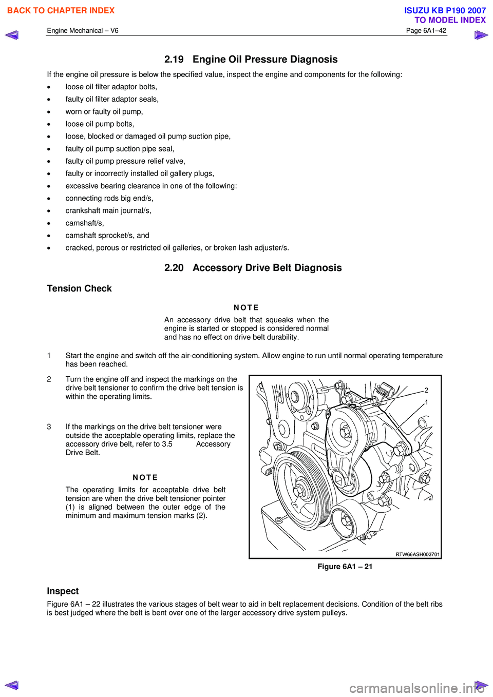
2 Turn the engine off and inspect the markings on the drive belt tensioner to confirm the drive belt tension is
within the operating limits.
3 If the markings on the drive belt tensioner were outside the acceptable operating limits, replace the
accessory drive belt, refer to 3.5 Accessory
Drive Belt.
NOTE
The operating limits for acceptable drive belt
tension are when the drive belt tensioner pointer
(1) is aligned between the outer edge of the
minimum and maximum tension marks (2).
Figure 6A1 – 21
Inspect
Figure 6A1 – 22 illustrates the various stages of belt wear to aid in belt replacement decisions. Condition of the belt ribs
is best judged where the belt is bent over one of the larger accessory drive system pulleys.
BACK TO CHAPTER INDEX
TO MODEL INDEX
ISUZU KB P190 2007
Page 2533 of 6020
Engine Mechanical – V6 Page 6A1–54
3.1 Engine Oil
The procedure outlined below is typically the same for both rear wheel drive and all wheel drive vehicles.
Check
The following procedure is applicable to both rear wheel and all wheel drive vehicles
1 Run the engine to bring it to normal operating temperature.
2 Park the vehicle on a level surface. A vehicle that is not level will affect the accuracy of the level reading.
3 Stop the engine and wait 5 to 10 minutes to allow the oil to drain back into the oil pan.
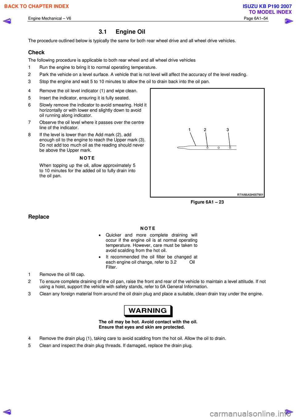
4 Remove the oil level indicator (1) and wipe clean.
5 Insert the indicator, ensuring it is fully seated.
6 Slowly remove the indicator to avoid smearing. Hold it horizontally or with lower end slightly down to avoid
oil running along indicator.
7 Observe the oil level where it passes over the centre line of the indicator.
8 If the level is lower than the Add mark (2), add enough oil to the engine to reach the Upper mark (3).
Do not add too much oil as the reading should never
be above the Upper mark.
NOTE
When topping up the oil, allow approximately 5
to 10 minutes for the added oil to fully drain into
the oil pan.
Figure 6A1 – 23
Replace
NOTE
• Quicker and more complete draining will
occur if the engine oil is at normal operating
temperature. However, care must be taken to
avoid scalding from the hot oil.
• It recommended the oil filter be changed at
each engine oil change, refer to 3.2 Oil
Filter.
1 Remove the oil fill cap.
2 To ensure complete draining of the oil pan, raise the front and rear of the vehicle to maintain a level attitude. If not using a hoist, support the vehicle with safety stands, refer to 0A General Information.
3 Clean any foreign material from around the oil drain plug and place a suitable, clean drain tray under the engine.
The oil may be hot. Avoid contact with the oil.
Ensure that eyes and skin are protected.
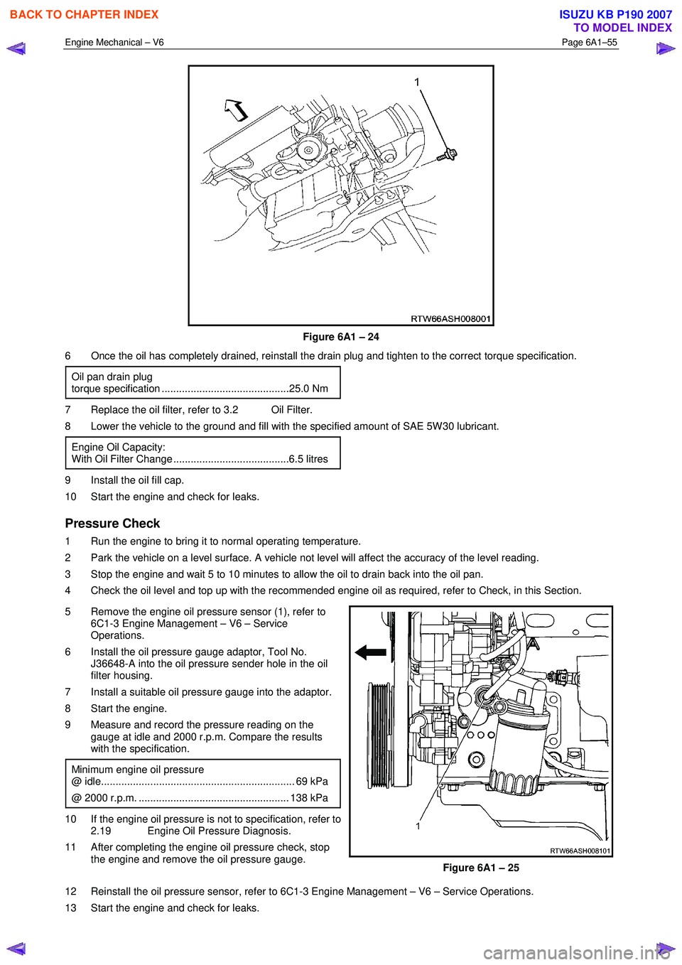
4 Remove the drain plug (1), taking care to avoid scalding from the hot oil. Allow the oil to drain.
5 Clean and inspect the drain plug threads. If damaged, replace the drain plug.
BACK TO CHAPTER INDEX
TO MODEL INDEX
ISUZU KB P190 2007
Page 2534 of 6020
Engine Mechanical – V6 Page 6A1–55
Figure 6A1 – 24
6 Once the oil has completely drained, reinstall the drain plug and tighten to the correct torque specification.
Oil pan drain plug
torque specification ............................................25.0 Nm
7 Replace the oil filter, refer to 3.2 Oil Filter.
8 Lower the vehicle to the ground and fill with the specified amount of SAE 5W 30 lubricant.
Engine Oil Capacity:
With Oil Filter Change ........................................6.5 litres
9 Install the oil fill cap.
10 Start the engine and check for leaks.
Pressure Check
1 Run the engine to bring it to normal operating temperature.
2 Park the vehicle on a level surface. A vehicle not level will affect the accuracy of the level reading.
3 Stop the engine and wait 5 to 10 minutes to allow the oil to drain back into the oil pan.
4 Check the oil level and top up with the recommended engine oil as required, refer to Check, in this Section.
5 Remove the engine oil pressure sensor (1), refer to 6C1-3 Engine Management – V6 – Service
Operations.
6 Install the oil pressure gauge adaptor, Tool No. J36648-A into the oil pressure sender hole in the oil
filter housing.
7 Install a suitable oil pressure gauge into the adaptor.
8 Start the engine.
9 Measure and record the pressure reading on the gauge at idle and 2000 r.p.m. Compare the results
with the specification.
Minimum engine oil pressure
@ idle................................................................... 69 kPa
@ 2000 r.p.m. .................................................... 138 kPa
10 If the engine oil pressure is not to specification, refer to 2.19 Engine Oil Pressure Diagnosis.
11 After completing the engine oil pressure check, stop the engine and remove the oil pressure gauge.
Figure 6A1 – 25
12 Reinstall the oil pressure sensor, refer to 6C1-3 Engine Management – V6 – Service Operations.
13 Start the engine and check for leaks.
BACK TO CHAPTER INDEX
TO MODEL INDEX
ISUZU KB P190 2007
Page 2677 of 6020
Engine Mechanical – V6 Page 6A1–198
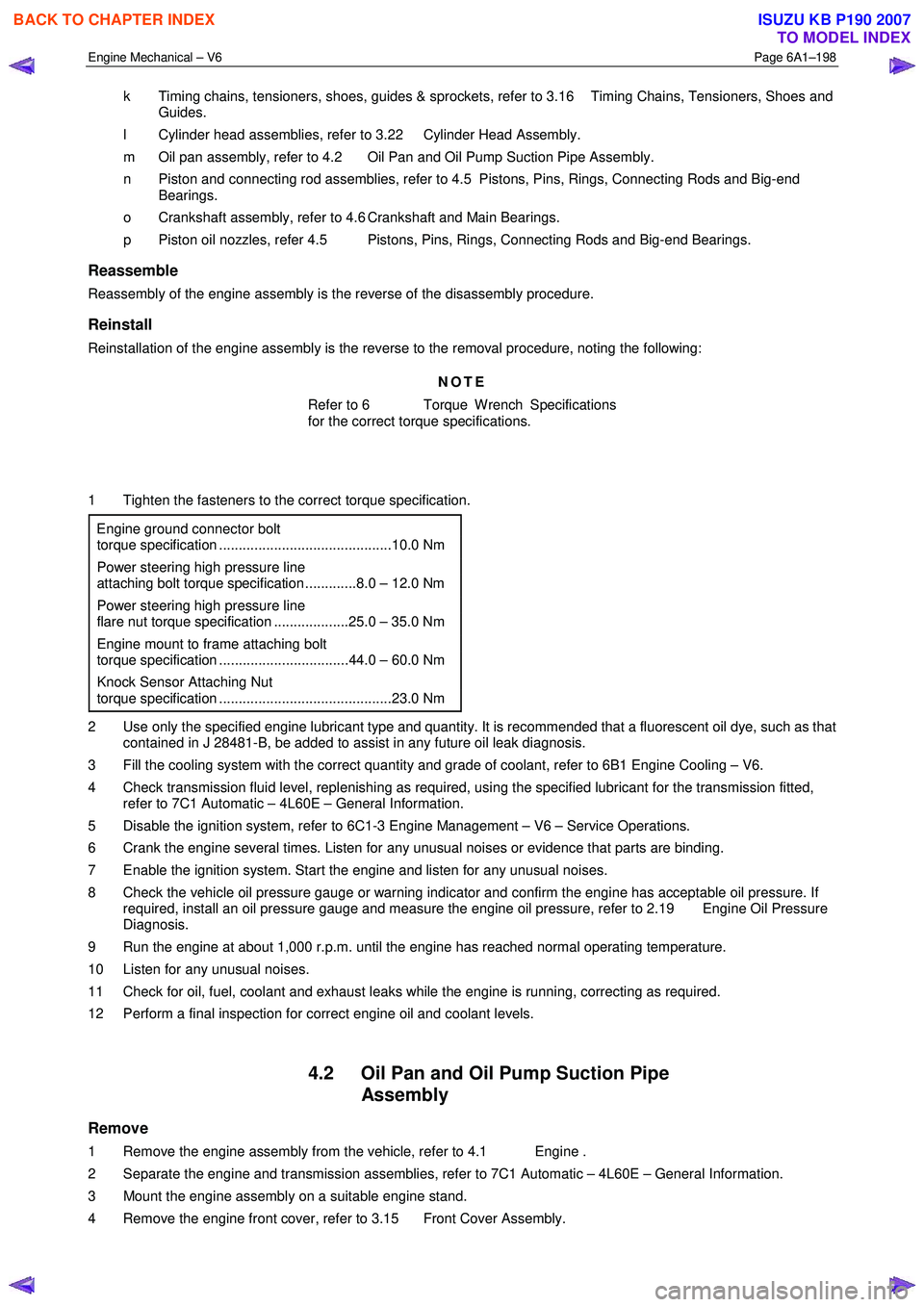
k Timing chains, tensioners, shoes, guides & sprockets, refer to 3.16 Timing Chains, Tensioners, Shoes and
Guides.
l Cylinder head assemblies, refer to 3.22 Cylinder Head Assembly.
m Oil pan assembly, refer to 4.2 Oil Pan and Oil Pump Suction Pipe Assembly.
n Piston and connecting rod assemblies, refer to 4.5 Pistons, Pins, Rings, Connecting Rods and Big-end Bearings.
o Crankshaft assembly, refer to 4.6 Crankshaft and Main Bearings.
p Piston oil nozzles, refer 4.5 Pistons, Pins, Rings, Connecting Rods and Big-end Bearings.
Reassemble
Reassembly of the engine assembly is the reverse of the disassembly procedure.
Reinstall
Reinstallation of the engine assembly is the reverse to the removal procedure, noting the following:
NOTE
Refer to 6 Torque Wrench Specifications
for the correct torque specifications.
1 Tighten the fasteners to the correct torque specification.
Engine ground connector bolt
torque specification ............................................10.0 Nm
Power steering high pressure line
attaching bolt torque specification .............8.0 – 12.0 Nm
Power steering high pressure line
flare nut torque specification ...................25.0 – 35.0 Nm
Engine mount to frame attaching bolt
torque specification .................................44.0 – 60.0 Nm
Knock Sensor Attaching Nut
torque specification ............................................23.0 Nm
2 Use only the specified engine lubricant type and quantity. It is recommended that a fluorescent oil dye, such as that contained in J 28481-B, be added to assist in any future oil leak diagnosis.
3 Fill the cooling system with the correct quantity and grade of coolant, refer to 6B1 Engine Cooling – V6.
4 Check transmission fluid level, replenishing as required, using the specified lubricant for the transmission fitted, refer to 7C1 Automatic – 4L60E – General Information.
5 Disable the ignition system, refer to 6C1-3 Engine Management – V6 – Service Operations.
6 Crank the engine several times. Listen for any unusual noises or evidence that parts are binding.
7 Enable the ignition system. Start the engine and listen for any unusual noises.
8 Check the vehicle oil pressure gauge or warning indicator and confirm the engine has acceptable oil pressure. If required, install an oil pressure gauge and measure the engine oil pressure, refer to 2.19 Engine Oil Pressure
Diagnosis.
9 Run the engine at about 1,000 r.p.m. until the engine has reached normal operating temperature.
10 Listen for any unusual noises.
11 Check for oil, fuel, coolant and exhaust leaks while the engine is running, correcting as required.
12 Perform a final inspection for correct engine oil and coolant levels.
4.2 Oil Pan and Oil Pump Suction Pipe Assembly
Remove
1 Remove the engine assembly from the vehicle, refer to 4.1 Engine .
2 Separate the engine and transmission assemblies, refer to 7C1 Automatic – 4L60E – General Information.
3 Mount the engine assembly on a suitable engine stand.
4 Remove the engine front cover, refer to 3.15 Front Cover Assembly.
BACK TO CHAPTER INDEX
TO MODEL INDEX
ISUZU KB P190 2007
Page 2687 of 6020
Engine Mechanical – V6 Page 6A1–208
5 Install the crankshaft rear oil seal housing attaching
bolts (1) to the cylinder block (2) and tighten to the
correct torque specification.
Crankshaft rear oil seal housing
attaching bolt torque specification .............8.0 – 12.0 Nm
Figure 6A1 – 373
4.5 Pistons, Pins, Rings, Connecting Rods and Big-end Bearings
Remove
1 Remove the engine assembly, refer to 4.1 Engine .
2 Remove both cylinder head assemblies, refer to 3.22 Cylinder Head Assembly.
3 Remove the oil pan assembly, refer to 4.2 Oil Pan and Oil Pump Suction Pipe Assembly.
4 Mark the top of the piston being removed to identify its specific bore.
5 Install Tool No. EN-46111 (1) onto the crankshaft (2).
6 Rotate the crankshaft until the piston being removed is at the bottom of its stroke; bottom dead centre
(BDC).
Figure 6A1 – 374
CAUTION
If the connecting rod bearings have been
used in a running engine, they must be
replaced with new connecting rod bearings
for reassembly.
7 Before removing the connecting rods, check the connecting rod side clearance using the following procedure: a Tap the connecting rod to one end of the crankshaft journal with a dead blow or wooden hammer.
b Using feeler gauges, measure the clearance between the crankshaft counterweight and the connecting rod.
c The connecting rod side clearance should not exceed specifications, refer to 5 Specifications.
BACK TO CHAPTER INDEX
TO MODEL INDEX
ISUZU KB P190 2007
Page 2775 of 6020
Engine Mechanical – V6 Page 6A1–296
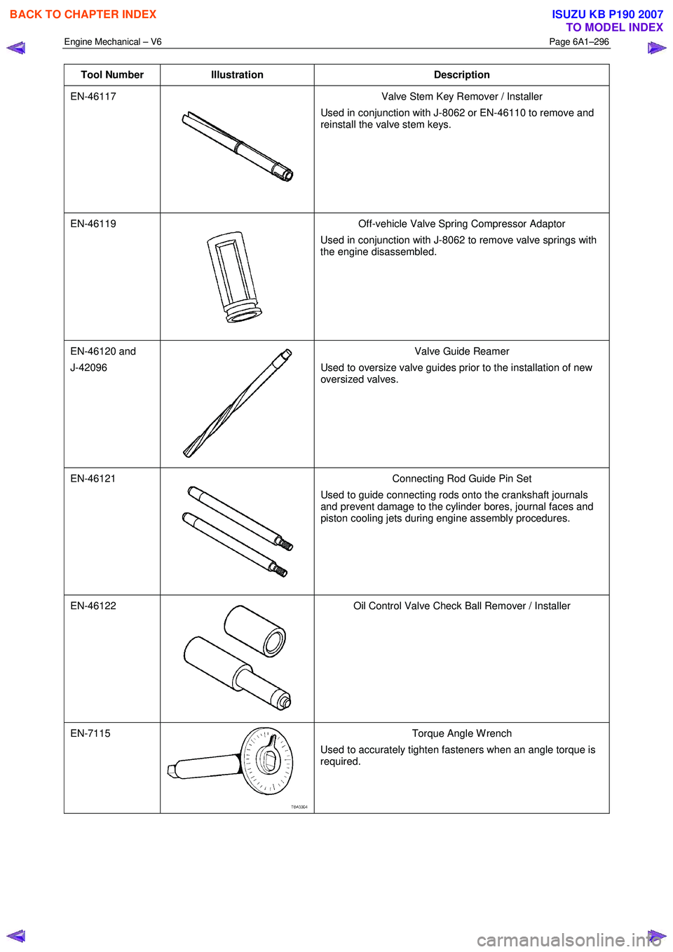
Tool Number Illustration Description
EN-46117
Valve Stem Key Remover / Installer
Used in conjunction with J-8062 or EN-46110 to remove and
reinstall the valve stem keys.
EN-46119
Off-vehicle Valve Spring Compressor Adaptor
Used in conjunction with J-8062 to remove valve springs with
the engine disassembled.
EN-46120 and
J-42096
Valve Guide Reamer
Used to oversize valve guides prior to the installation of new
oversized valves.
EN-46121
Connecting Rod Guide Pin Set
Used to guide connecting rods onto the crankshaft journals
and prevent damage to the cylinder bores, journal faces and
piston cooling jets during engine assembly procedures.
EN-46122
Oil Control Valve Check Ball Remover / Installer
EN-7115 Torque Angle W rench
Used to accurately tighten fasteners when an angle torque is
required.
BACK TO CHAPTER INDEX
TO MODEL INDEX
ISUZU KB P190 2007
Page 2779 of 6020
Engine Mechanical – V6 Page 6A1–2
Page 6A1–2
Visual / Physical Inspection ................................................................................................... .............................31
Intermittent ................................................................................................................... ........................................31
2.3 Engine Misfire without In ternal Engine Noises .................................................................................. ...............32
2.4 Engine Misfire with Abnormal In ternal Lower Engine Noises...................................................................... ....34
2.5 Engine Misfire with Abno rmal Valve Train Noise ................................................................................. .............35
2.6 Engine Misfire with Coolant Consumption ........................................................................................ ................36
2.7 Engine Misfire with E xcessive Oil Consumption .................................................................................. ............37
2.8 Engine Noise on Start-up, but only Lasting a Few Seconds ....................................................................... .....38
2.9 Upper Engine Noise, Rega rdless of Engine Speed................................................................................. ..........39
2.10 Lower Engine Noise, Rega rdless of Engine Speed ................................................................................. .........40
2.11 Engine Noise Under Load ................................................................................................................................... 41
2.12 Engine Will Not Crank – Crankshaft Will Not Rotate ............................................................................. ...........42
2.13 Coolant in Com bustion Chamber .................................................................................................. .....................43
Definition ..................................................................................................................... .........................................43
2.14 Coolant in Engine Oil........................................................................................................................................... 44
Definition ..............................................................................................................................................................44
2.15 Engine Compression Test........................................................................................................ ...........................45
Preliminary Steps................................................................................................................................................. 45
Engine Cylinder Compression Test ............................................................................................... ....................45
Test Result Evaluation ......................................................................................................... ...............................45
2.16 Cylinder Leakage Test .......................................................................................................... ...............................46
2.17 Engine Oil Consumption Diagnosis ............................................................................................... ....................47
Definition ..................................................................................................................... .........................................47
2.18 Engine Oil Leak Diagnosis .................................................................................................................................. 48
Introduction ..........................................................................................................................................................48
Locating and Identifying the Leak .............................................................................................. ........................48
Visual Inspection .............................................................................................................. ...................................48
Powder Method .................................................................................................................. ..................................48
Black Light and Dye Method ............................................................................................................................... 48
Possible Causes for Engine Oil Leaks ........................................................................................... ....................49
2.19 Engine Oil Pressu re Diagnosis .................................................................................................. .........................50
2.20 Accessory Drive Belt Diagnosis ................................................................................................. ........................51
Tension Check .................................................................................................................. ...................................51
Inspect ........................................................................................................................ ..........................................52
Drive Belt Chirp .................................................................................................................................................... 53
Definition ..................................................................................................................... .....................................53
Diagnostic Aids................................................................................................................................................. 53
Test Description ............................................................................................................... ................................53
Diagnostic Table............................................................................................................... ................................54
Drive Belt Squeal .............................................................................................................. ...................................55
Definition ..................................................................................................................... .....................................55
Diagnostic Aids................................................................................................................................................. 55
Test Description ............................................................................................................... ................................55
Diagnostic Table............................................................................................................... ................................55
Drive Belt Whine .................................................................................................................................................. 57
Definition ..................................................................................................................... .....................................57
Diagnostic Aids................................................................................................................................................. 57
Test Description ............................................................................................................... ................................57
Diagnostic Table............................................................................................................... ................................57
Drive Belt Rumble .............................................................................................................. ..................................58
Definition ..................................................................................................................... .....................................58
Diagnostic Aids................................................................................................................................................. 58
Test Description ............................................................................................................... ................................58
Diagnostic Table............................................................................................................... ................................58
Drive Belt Vibration........................................................................................................... ...................................60
Definition ..................................................................................................................... .....................................60
Diagnostic Aids................................................................................................................................................. 60
Test Description ............................................................................................................... ................................60
Diagnostic Table............................................................................................................... ................................60
Drive Belt Falls Off ........................................................................................................... ....................................62
BACK TO CHAPTER INDEX
TO MODEL INDEX
ISUZU KB P190 2007