2007 ISUZU KB P190 heater
[x] Cancel search: heaterPage 3514 of 6020
Engine Management – V6 – Diagnostics Page 6C1-2–236
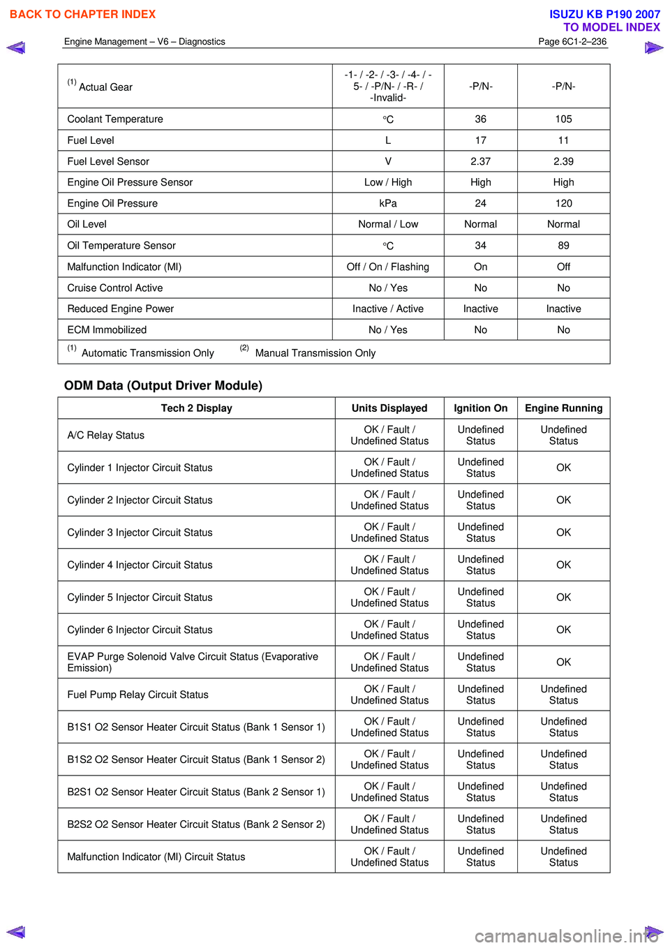
(1) Actual Gear -1- / -2- / -3- / -4- / -
5- / -P/N- / -R- / -Invalid- -P/N- -P/N-
Coolant Temperature
°C 36 105
Fuel Level
L 17 11
Fuel Level Sensor V 2.37 2.39
Engine Oil Pressure Sensor Low / High High High
Engine Oil Pressure kPa 24 120
Oil Level Normal / Low Normal Normal
Oil Temperature Sensor
°C 34 89
Malfunction Indicator (MI)
Off / On / Flashing On Off
Cruise Control Active No / Yes No No
Reduced Engine Power Inactive / Active Inactive Inactive
ECM Immobilized No / Yes No No
(1) Automatic Transmission Only (2) Manual Transmission Only
ODM Data (Output Driver Module)
Tech 2 Display Units Displayed Ignition On Engine Running
A/C Relay Status OK / Fault /
Undefined Status Undefined
Status Undefined
Status
Cylinder 1 Injector Circuit Status OK / Fault /
Undefined Status Undefined
Status OK
Cylinder 2 Injector Circuit Status
OK / Fault /
Undefined Status Undefined
Status OK
Cylinder 3 Injector Circuit Status
OK / Fault /
Undefined Status Undefined
Status OK
Cylinder 4 Injector Circuit Status
OK / Fault /
Undefined Status Undefined
Status OK
Cylinder 5 Injector Circuit Status
OK / Fault /
Undefined Status Undefined
Status OK
Cylinder 6 Injector Circuit Status
OK / Fault /
Undefined Status Undefined
Status OK
EVAP Purge Solenoid Valve Circuit Status (Evaporative
Emission) OK / Fault /
Undefined Status Undefined
Status OK
Fuel Pump Relay Circuit Status
OK / Fault /
Undefined Status Undefined
Status Undefined
Status
B1S1 O2 Sensor Heater Circuit Status (Bank 1 Sensor 1) OK / Fault /
Undefined Status Undefined
Status Undefined
Status
B1S2 O2 Sensor Heater Circuit Status (Bank 1 Sensor 2) OK / Fault /
Undefined Status Undefined
Status Undefined
Status
B2S1 O2 Sensor Heater Circuit Status (Bank 2 Sensor 1) OK / Fault /
Undefined Status Undefined
Status Undefined
Status
B2S2 O2 Sensor Heater Circuit Status (Bank 2 Sensor 2) OK / Fault /
Undefined Status Undefined
Status Undefined
Status
Malfunction Indicator (MI) Circuit Status OK / Fault /
Undefined Status Undefined
Status Undefined
Status
BACK TO CHAPTER INDEX
TO MODEL INDEX
ISUZU KB P190 2007
Page 3517 of 6020
Engine Management – V6 – Diagnostics Page 6C1-2–239
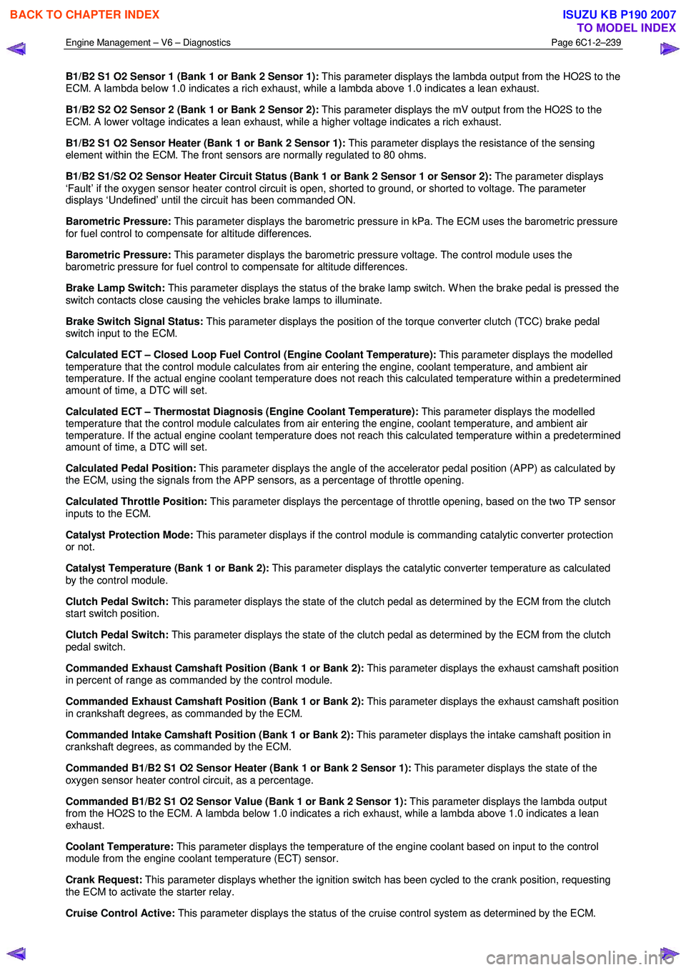
B1/B2 S1 O2 Sensor 1 (Bank 1 or Bank 2 Sensor 1): This parameter displays the lambda output from the HO2S to the
ECM. A lambda below 1.0 indicates a rich exhaust, while a lambda above 1.0 indicates a lean exhaust.
B1/B2 S2 O2 Sensor 2 (Bank 1 or Bank 2 Sensor 2): This parameter displays the mV output from the HO2S to the
ECM. A lower voltage indicates a lean exhaust, while a higher voltage indicates a rich exhaust.
B1/B2 S1 O2 Sensor Heater (Bank 1 or Bank 2 Sensor 1): This parameter displays the resistance of the sensing
element within the ECM. The front sensors are normally regulated to 80 ohms.
B1/B2 S1/S2 O2 Sensor Heater Circuit Status (Bank 1 or Bank 2 Sensor 1 or Sensor 2): The parameter displays
‘Fault’ if the oxygen sensor heater control circuit is open, shorted to ground, or shorted to voltage. The parameter
displays ‘Undefined’ until the circuit has been commanded ON.
Barometric Pressure: This parameter displays the barometric pressure in kPa. The ECM uses the barometric pressure
for fuel control to compensate for altitude differences.
Barometric Pressure: This parameter displays the barometric pressure voltage. The control module uses the
barometric pressure for fuel control to compensate for altitude differences.
Brake Lamp Switch: This parameter displays the status of the brake lamp switch. W hen the brake pedal is pressed the
switch contacts close causing the vehicles brake lamps to illuminate.
Brake Switch Signal Status: This parameter displays the position of the torque converter clutch (TCC) brake pedal
switch input to the ECM.
Calculated ECT – Closed Loop Fuel Control (Engine Coolant Temperature): This parameter displays the modelled
temperature that the control module calculates from air entering the engine, coolant temperature, and ambient air
temperature. If the actual engine coolant temperature does not reach this calculated temperature within a predetermined
amount of time, a DTC will set.
Calculated ECT – Thermostat Diagnosis (Engine Coolant Temperature): This parameter displays the modelled
temperature that the control module calculates from air entering the engine, coolant temperature, and ambient air
temperature. If the actual engine coolant temperature does not reach this calculated temperature within a predetermined
amount of time, a DTC will set.
Calculated Pedal Position: This parameter displays the angle of the accelerator pedal position (APP) as calculated by
the ECM, using the signals from the APP sensors, as a percentage of throttle opening.
Calculated Throttle Position: This parameter displays the percentage of throttle opening, based on the two TP sensor
inputs to the ECM.
Catalyst Protection Mode: This parameter displays if the control module is commanding catalytic converter protection
or not.
Catalyst Temperature (Bank 1 or Bank 2): This parameter displays the catalytic converter temperature as calculated
by the control module.
Clutch Pedal Switch: This parameter displays the state of the clutch pedal as determined by the ECM from the clutch
start switch position.
Clutch Pedal Switch: This parameter displays the state of the clutch pedal as determined by the ECM from the clutch
pedal switch.
Commanded Exhaust Camshaft Position (Bank 1 or Bank 2): This parameter displays the exhaust camshaft position
in percent of range as commanded by the control module.
Commanded Exhaust Camshaft Position (Bank 1 or Bank 2): This parameter displays the exhaust camshaft position
in crankshaft degrees, as commanded by the ECM.
Commanded Intake Camshaft Position (Bank 1 or Bank 2): This parameter displays the intake camshaft position in
crankshaft degrees, as commanded by the ECM.
Commanded B1/B2 S1 O2 Sensor Heater (Bank 1 or Bank 2 Sensor 1): This parameter displays the state of the
oxygen sensor heater control circuit, as a percentage.
Commanded B1/B2 S1 O2 Sensor Value (Bank 1 or Bank 2 Sensor 1): This parameter displays the lambda output
from the HO2S to the ECM. A lambda below 1.0 indicates a rich exhaust, while a lambda above 1.0 indicates a lean
exhaust.
Coolant Temperature: This parameter displays the temperature of the engine coolant based on input to the control
module from the engine coolant temperature (ECT) sensor.
Crank Request: This parameter displays whether the ignition switch has been cycled to the crank position, requesting
the ECM to activate the starter relay.
Cruise Control Active: This parameter displays the status of the cruise control system as determined by the ECM.
BACK TO CHAPTER INDEX
TO MODEL INDEX
ISUZU KB P190 2007
Page 3526 of 6020
Engine Management – V6 – Service Operations Page 6C1-3–2
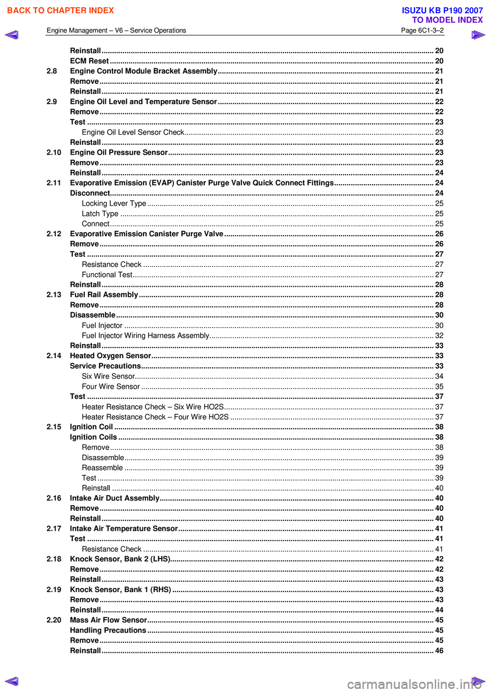
Reinstall ................................................................................................................................................................ 20
ECM Reset ...................................................................................................................... ...................................... 20
2.8 Engine Control Module Bracket Assembly......................................................................................... ............... 21
Remove ................................................................................................................................................................. 21
Reinstall ................................................................................................................................................................ 21
2.9 Engine Oil Level and Temperature Sensor ........................................................................................ ................ 22
Remove ................................................................................................................................................................. 22
Test ....................................................................................................................................................................... 23
Engine Oil Level Sensor Check .................................................................................................. ...................... 23
Reinstall ................................................................................................................................................................ 23
2.10 Engine Oil Pressure Sensor..................................................................................................... ........................... 23
Remove ................................................................................................................................................................. 23
Reinstall ................................................................................................................................................................ 24
2.11 Evaporative Emission (EVAP) Canister Purge Valve Quick Connect Fittings ................................................ 24
Disconnect..................................................................................................................... ....................................... 24
Locking Lever Type ............................................................................................................. ............................. 25
Latch Type ....................................................................................................................................................... 25
Connect ............................................................................................................................................................ 25
2.12 Evaporative Emission Canister Purge Valve ...................................................................................... ............... 26
Remove ................................................................................................................................................................. 26
Test ....................................................................................................................................................................... 27
Resistance Check ............................................................................................................... ............................. 27
Functional Test................................................................................................................................................. 27
Reinstall ................................................................................................................................................................ 28
2.13 Fuel Rail Assembly ............................................................................................................. ................................. 28
Remove ................................................................................................................................................................. 28
Disassemble ......................................................................................................................................................... 30
Fuel Injector ..................................................................................................................................................... 30
Fuel Injector Wiring Harness Assembly.......................................................................................... .................. 32
Reinstall ................................................................................................................................................................ 33
2.14 Heated Oxygen Sensor........................................................................................................... ............................. 33
Service Precautions............................................................................................................................................. 33
Six Wire Sensor................................................................................................................................................ 34
Four Wire Sensor ............................................................................................................... .............................. 35
Test ....................................................................................................................................................................... 37
Heater Resistance Check – Six Wire HO2S........................................................................................ ............. 37
Heater Resistance Check – Four Wire HO2S ....................................................................................... ........... 37
2.15 Ignition Coil .......................................................................................................................................................... 38
Ignition Coils ................................................................................................................. ....................................... 38
Remove ............................................................................................................................................................ 38
Disassemble..................................................................................................................................................... 39
Reassemble ..................................................................................................................................................... 39
Test .................................................................................................................................................................. 39
Reinstall ........................................................................................................................................................... 40
2.16 Intake Air Duct Assembly....................................................................................................... ............................. 40
Remove ................................................................................................................................................................. 40
Reinstall ................................................................................................................................................................ 40
2.17 Intake Air Temperature Sensor .................................................................................................. ......................... 41
Test ....................................................................................................................................................................... 41
Resistance Check ............................................................................................................... ............................. 41
2.18 Knock Sensor, Bank 2 (LHS)..................................................................................................... .......................... 42
Remove ................................................................................................................................................................. 42
Reinstall ................................................................................................................................................................ 43
2.19 Knock Sensor, Bank 1 (RHS) ..................................................................................................... ......................... 43
Remove ................................................................................................................................................................. 43
Reinstall ................................................................................................................................................................ 44
2.20 Mass Air Flow Sensor........................................................................................................... ............................... 45
Handling Precautions .......................................................................................................................................... 45
Remove ................................................................................................................................................................. 45
Reinstall ................................................................................................................................................................ 46
BACK TO CHAPTER INDEX
TO MODEL INDEX
ISUZU KB P190 2007
Page 3530 of 6020
Engine Management – V6 – Service Operations Page 6C1-3–6
Basic Diagnostic Tools Required
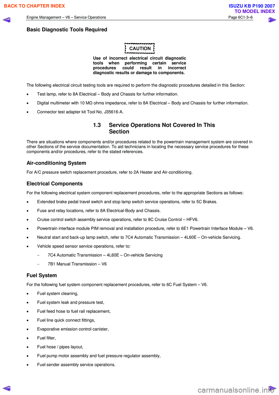
Use of incorrect electrical circuit diagnostic
tools when performing certain service
procedures could result in incorrect
diagnostic results or damage to components.
The following electrical circuit testing tools are required to perform the diagnostic procedures detailed in this Section:
• Test lamp, refer to 8A Electrical – Body and Chassis for further information.
• Digital multimeter with 10 M Ω ohms impedance, refer to 8A Electrical – Body and Chassis for further information.
• Connector test adapter kit Tool No. J35616-A.
1.3 Service Operations Not Covered In This
Section
There are situations where components and/or procedures related to the powertrain management system are covered in
other Sections of the service documentation. To aid technicians in locating the necessary service procedures for these
components and/or procedures, refer to the stated references.
Air-conditioning System
For A/C pressure switch replacement procedure, refer to 2A Heater and Air-conditioning.
Electrical Components
For the following electrical system component replacement procedures, refer to the appropriate Sections as follows:
• Extended brake pedal travel switch and stop lamp switch service operations, refer to 5C Brakes.
• Fuse and relay locations, refer to 8A Electrical-Body and Chassis.
• Cruise control switch assembly service operations, refer to 8C Cruise Control – HFV6.
• Powertrain interface module PIM removal and installation procedure, refer to 6E1 Powertrain Interface Module – V6.
• Neutral start and back-up lamp switch, refer to 7C4 Automatic Transmission – 4L60E – On-vehicle Servicing.
• Vehicle speed sensor service operations, refer to:
− 7C4 Automatic Transmission – 4L60E – On-vehicle Servicing
− 7B1 Manual Transmission – V6
Fuel System
For the following fuel system component replacement procedures, refer to 6C Fuel System – V6.
• Fuel system cleaning,
• Fuel system leak and pressure test,
• Fuel feed hose to fuel rail replacement,
• Fuel line quick connect fittings,
• Evaporative emission control canister,
• Fuel filter,
• Fuel hose / pipes layout,
• Fuel pump motor assembly and fuel pressure regulator assembly,
• Fuel sender assembly service operations.
BACK TO CHAPTER INDEX
TO MODEL INDEX
ISUZU KB P190 2007
Page 3561 of 6020
Engine Management – V6 – Service Operations Page 6C1-3–37
Test
Under no circumstances should battery
voltage be applied to the heated oxygen
sensor (HO2S) heater.
To prevent component damage use connector
test adaptor kit J 35616-A.
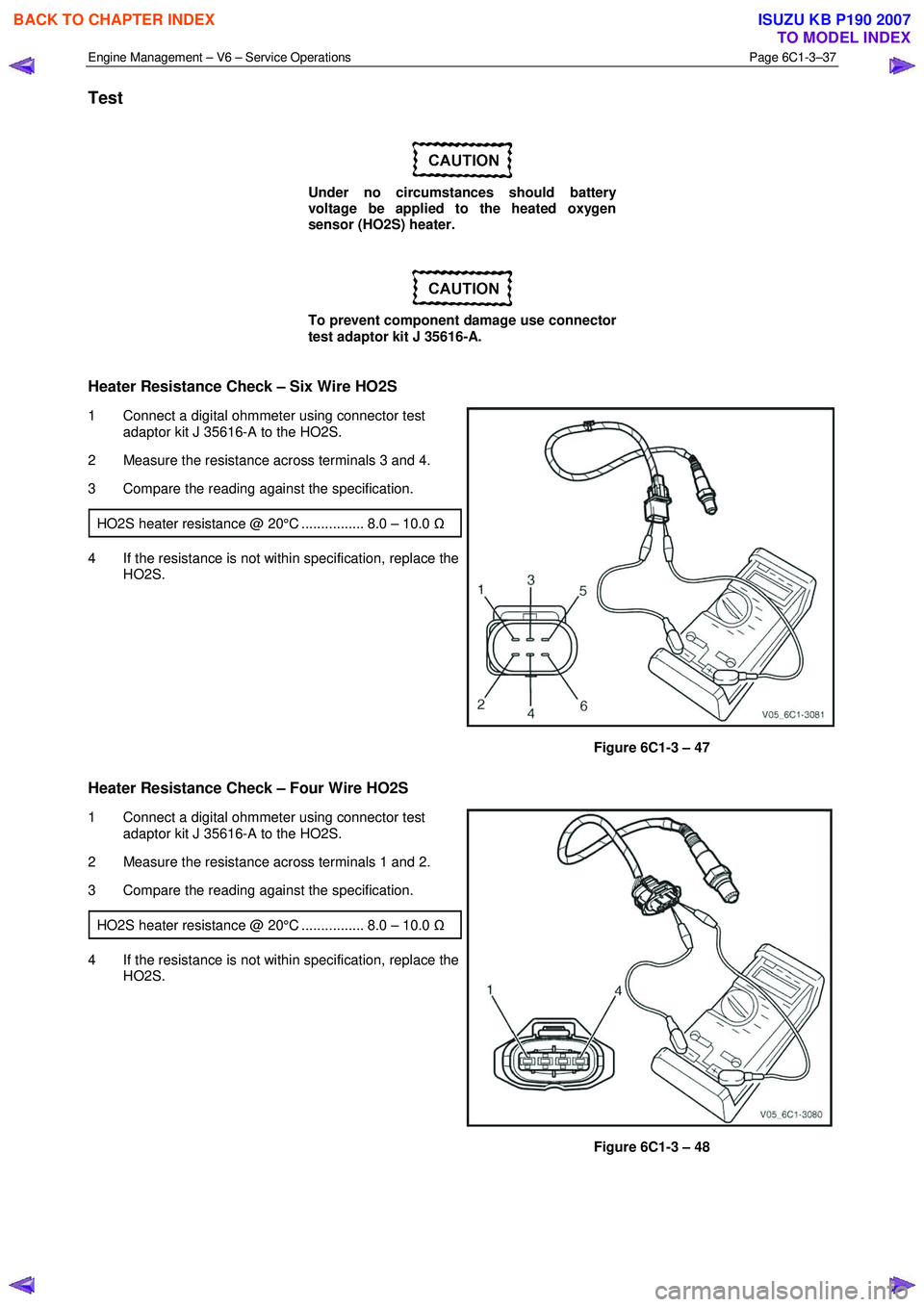
Heater Resistance Check – Six Wire HO2S
1 Connect a digital ohmmeter using connector test adaptor kit J 35616-A to the HO2S.
2 Measure the resistance across terminals 3 and 4.
3 Compare the reading against the specification.
HO2S heater resistance @ 20°C ................ 8.0 – 10.0 Ω
4 If the resistance is not within specification, replace the
HO2S.
Figure 6C1-3 – 47
Heater Resistance Check – Four Wire HO2S
1 Connect a digital ohmmeter using connector test
adaptor kit J 35616-A to the HO2S.
2 Measure the resistance across terminals 1 and 2.
3 Compare the reading against the specification.
HO2S heater resistance @ 20°C ................ 8.0 – 10.0 Ω
4 If the resistance is not within specification, replace the
HO2S.
Figure 6C1-3 – 48
BACK TO CHAPTER INDEX
TO MODEL INDEX
ISUZU KB P190 2007
Page 3582 of 6020
Engine Management – V6 – Service Operations Page 6C1-3–58
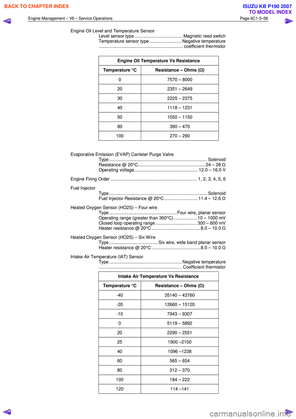
Engine Oil Level and Temperature Sensor
Level sensor type ....................................... Magnetic reed switch
Temperature sensor type .......................... Negative temperature
................................................................... coefficient thermistor
Engine Oil Temperature Vs Resistance
Temperature °C Resistance – Ohms ( Ω)
0 7570 – 8000
20 2351 – 2649
30 2225 – 2375
40 1118 – 1231
50 1050 – 1150
80 380 – 470
100 270 – 290
Evaporative Emission (EVAP) Canister Purge Valve
Type .............................................................................. Solenoid
Resistance @ 20°C...................................................... 24 – 28 Ω
Operating voltage................................................... 12.0 – 16.0 V
Engine Firing Order ..................................................................... 1, 2, 3, 4, 5, 6
Fuel Injector
Type .............................................................................. Solenoid
Fuel Injector Resistance @ 20°C ........................... 11.4 – 12.6 Ω
Heated Oxygen Sensor (HO2S) – Four wire
Type ...................................................... Four wire, planar sensor
Operating range (greater than 360°C) .................. 10 – 1000 mV
Closed loop operating range ................................. 300 – 600 mV
Heater resistance @ 20°C ....................................... 8.0 – 10.0 Ω
Heated Oxygen Sensor (HO2S) – Six W ire
Type ....................................... Six wire, wide band planar sensor
Heater resistance @ 20°C ....................................... 8.0 – 10.0 Ω
Intake Air Temperature (IAT) Sensor
Type .......................................................... Negative temperature
.................................................................. Coefficient thermistor
Intake Air Temperature Vs Resistance
Temperature °C Resistance – Ohms ( Ω)
-40 35140 – 43760
-20 12660 – 15120
-10 7943 – 9307
0 5119 – 5892
20 2290 – 2551
25 1900 –2100
40 1096 –1238
60 565 – 654
80 312 – 370
100 184 – 222
120 114 –141
BACK TO CHAPTER INDEX
TO MODEL INDEX
ISUZU KB P190 2007
Page 4940 of 6020
8A-2 ELECTRICAL-BODY AND CHASSIS
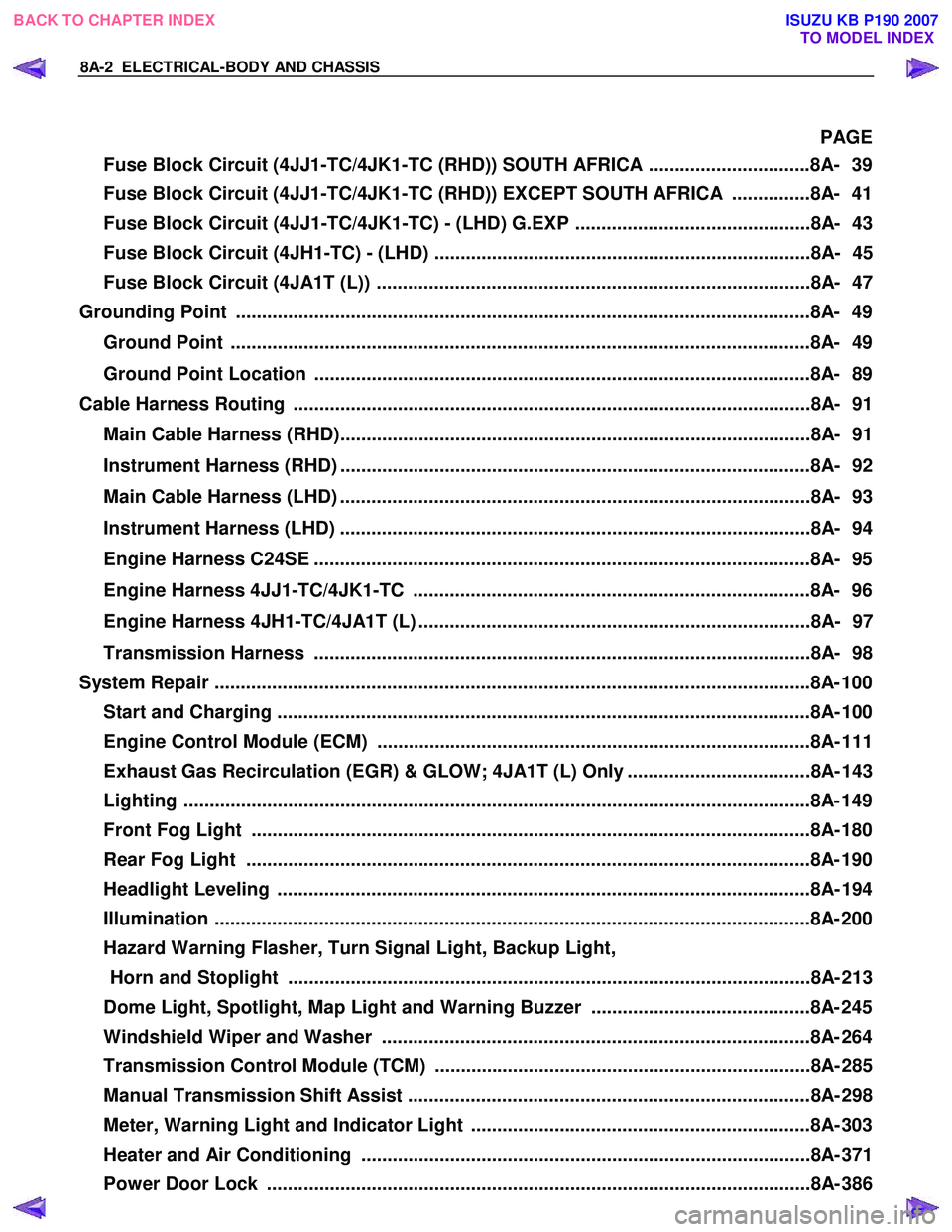
PAGE
Fuse Block Circuit (4JJ1-TC/4JK1-TC (RHD)) SOUTH AFRICA ...............................8A- 39
Fuse Block Circuit (4JJ1-TC/4JK1-TC (RHD)) EXCEPT SOUTH AFRICA ...............8A- 41
Fuse Block Circuit (4JJ1-TC/4JK1-TC) - (LHD) G.EXP .............................................8A- 43
Fuse Block Circuit (4JH1-TC) - (LHD) ........................................................................8A- 45
Fuse Block Circuit (4JA1T (L)) ...................................................................................8A- 47
Grounding Point ..............................................................................................................8 A- 49
Ground Point ...............................................................................................................8A- 49
Ground Point Location ...............................................................................................8A- 89
Cable Harness Routing ...................................................................................................8A- 91
Main Cable Harness (RHD)..........................................................................................8A- 91
Instrument Harness (RHD) ..........................................................................................8A- 92
Main Cable Harness (LHD) ..........................................................................................8A- 93
Instrument Harness (LHD) ..........................................................................................8A- 94
Engine Harness C24SE ...............................................................................................8A- 95
Engine Harness 4JJ1-TC/4JK1-TC ............................................................................8A- 96
Engine Harness 4JH1-TC/4JA1T (L) ...........................................................................8A- 97
Transmission Harness ...............................................................................................8A- 98
System Repair ................................................................................................................. .8A- 100
Start and Charging ......................................................................................................8A- 10 0
Engine Control Module (ECM) ...................................................................................8A- 111
Exhaust Gas Recirculation (EGR) & GLOW; 4JA1T (L) Only ...................................8A- 143
Lighting ...................................................................................................................... ..8A- 149
Front Fog Light ...........................................................................................................8A- 180
Rear Fog Light ............................................................................................................8A- 190
Headlight Leveling ......................................................................................................8A- 19 4
Illumination .................................................................................................................. 8A- 200
Hazard Warning Flasher, Turn Signal Light, Backup Light, Horn and Stoplight ....................................................................................................8A- 213
Dome Light, Spotlight, Map Light and Warning Buzzer ..........................................8A- 245
Windshield Wiper and Washer ..................................................................................8A- 264
Transmission Control Module (TCM) ........................................................................8A- 285
Manual Transmission Shift Assist .............................................................................8A- 298
Meter, Warning Light and Indicator Light .................................................................8A- 303
Heater and Air Conditioning ......................................................................................8A- 371
Power Door Lock ........................................................................................................8A- 386
BACK TO CHAPTER INDEX
TO MODEL INDEX
ISUZU KB P190 2007
Page 4950 of 6020
8A-12 ELECTRICAL-BODY AND CHASSIS
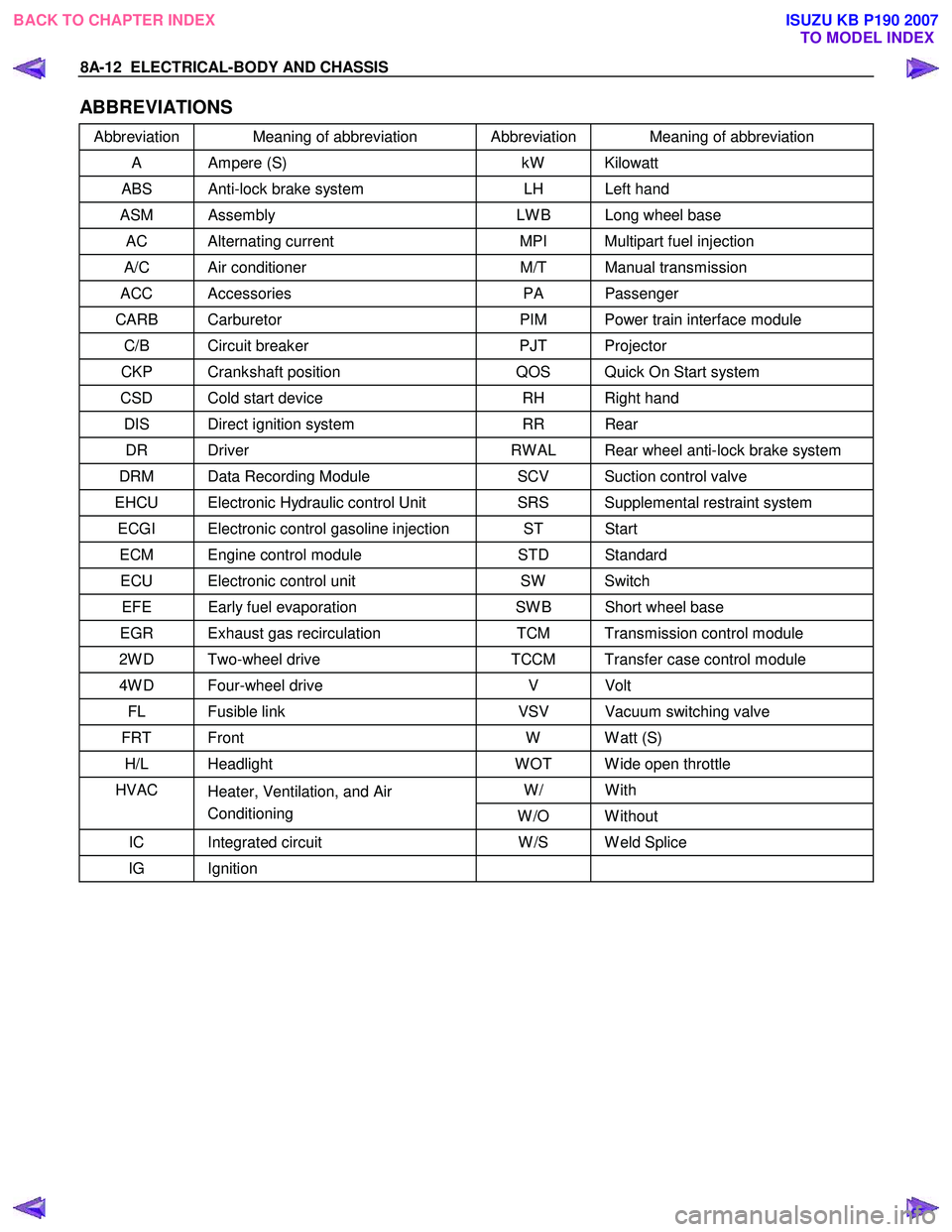
ABBREVIATIONS
Abbreviation Meaning of abbreviation Abbreviation Meaning of abbreviation
A Ampere (S) kW Kilowatt
ABS Anti-lock brake system LH Left hand
ASM Assembly LW B Long wheel base
AC Alternating current MPI Multipart fuel injection
A/C Air conditioner M/T Manual transmission
ACC Accessories PA Passenger
CARB Carburetor PIM Power train interface module
C/B Circuit breaker PJT Projector
CKP Crankshaft position QOS Quick On Start system
CSD Cold start device RH Right hand
DIS Direct ignition system RR Rear
DR Driver RW AL Rear wheel anti-lock brake system
DRM Data Recording Module SCV Suction control valve
EHCU Electronic Hydraulic control Unit SRS Supplemental restraint system
ECGI Electronic control gasoline injection ST Start
ECM Engine control module STD Standard
ECU Electronic control unit SW Switch
EFE Early fuel evaporation SW B Short wheel base
EGR Exhaust gas recirculation TCM Transmission control module
2W D Two-wheel drive TCCM Transfer case control module
4W D Four-wheel drive V Volt
FL Fusible link VSV Vacuum switching valve
FRT Front W W att (S)
H/L Headlight W OT W ide open throttle
W/ With HVAC
Heater, Ventilation, and Air
Conditioning W /O W ithout
IC Integrated circuit W /S W eld Splice
IG Ignition
BACK TO CHAPTER INDEX
TO MODEL INDEXISUZU KB P190 2007