2007 ISUZU KB P190 ECO mode
[x] Cancel search: ECO modePage 1207 of 6020
Engine Control System (4JH1) 6E-173
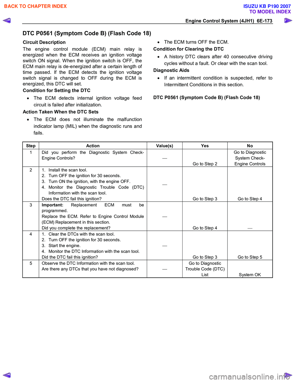
DTC P0561 (Symptom Code B) (Flash Code 18)
Circuit Description
The engine control module (ECM) main relay is
energized when the ECM receives an ignition voltage
switch ON signal. W hen the ignition switch is OFF, the
ECM main relay is de-energized after a certain length o
f
time passed. If the ECM detects the ignition voltage
switch signal is changed to OFF during the ECM is
energized, this DTC will set.
Condition for Setting the DTC
• The ECM detects internal ignition voltage feed
circuit is failed after initialization.
Action Taken When the DTC Sets
• The ECM does not illuminate the malfunction
indicator lamp (MIL) when the diagnostic runs and
fails.
•
The ECM turns OFF the ECM.
Condition for Clearing the DTC
• A history DTC clears after 40 consecutive driving
cycles without a fault. Or clear with the scan tool.
Diagnostic Aids
• If an intermittent condition is suspected, refer to
Intermittent Conditions in this section.
DTC P0561 (Symptom Code B) (Flash Code 18)
Step Action Value(s) Yes No
1 Did you perform the Diagnostic System Check-
Engine Controls?
Go to Step 2 Go to Diagnostic
System Check-
Engine Controls
2 1. Install the scan tool. 2. Turn OFF the ignition for 30 seconds.
3. Turn ON the ignition, with the engine OFF.
4. Monitor the Diagnostic Trouble Code (DTC) Information with the scan tool.
Does the DTC fail this ignition?
Go to Step 3 Go to Step 4
3 Important: Replacement ECM must be
programmed.
Replace the ECM. Refer to Engine Control Module
(ECM) Replacement in this section.
Did you complete the replacement?
Go to Step 4
4 1. Clear the DTCs with the scan tool.
2. Turn OFF the ignition for 30 seconds.
3. Start the engine.
4. Monitor the DTC Information with the scan tool.
Did the DTC fail this ignition?
Go to Step 3 Go to Step 5
5 Observe the DTC Information with the scan tool. Are there any DTCs that you have not diagnosed? Go to Diagnostic
Trouble Code (DTC) List System OK
BACK TO CHAPTER INDEX
TO MODEL INDEX
ISUZU KB P190 2007
Page 1208 of 6020
6E-174 Engine Control System (4JH1)
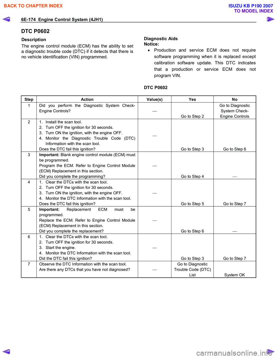
DTC P0602
Description
The engine control module (ECM) has the ability to set
a diagnostic trouble code (DTC) if it detects that there is
no vehicle identification (VIN) programmed.
Diagnostic Aids
Notice:
• Production and service ECM does not require
software programming when it is replaced except
calibration software update. This DTC indicates
that a production or service ECM does not
program VIN.
DTC P0602
Step Action Value(s) Yes No
1 Did you perform the Diagnostic System Check-
Engine Controls?
Go to Step 2 Go to Diagnostic
System Check-
Engine Controls
2 1. Install the scan tool. 2. Turn OFF the ignition for 30 seconds.
3. Turn ON the ignition, with the engine OFF.
4. Monitor the Diagnostic Trouble Code (DTC) Information with the scan tool.
Does the DTC fail this ignition?
Go to Step 3 Go to Step 6
3 Important: Blank engine control module (ECM) must
be programmed.
Program the ECM. Refer to Engine Control Module
(ECM) Replacement in this section.
Did you complete the programming?
Go to Step 4
4 1. Clear the DTCs with the scan tool.
2. Turn OFF the ignition for 30 seconds.
3. Turn ON the ignition, with the engine OFF.
4. Monitor the DTC Information with the scan tool.
Does the DTC fail this ignition?
Go to Step 5 Go to Step 7
5 Important: Replacement ECM must be
programmed.
Replace the ECM. Refer to Engine Control Module
(ECM) Replacement in this section.
Did you complete the replacement?
Go to Step 6
6 1. Clear the DTCs with the scan tool.
2. Turn OFF the ignition for 30 seconds.
3. Start the engine.
4. Monitor the DTC Information with the scan tool.
Did the DTC fail this ignition?
Go to Step 3 Go to Step 7
7 Observe the DTC Information with the scan tool. Are there any DTCs that you have not diagnosed? Go to Diagnostic
Trouble Code (DTC) List System OK
BACK TO CHAPTER INDEX
TO MODEL INDEX
ISUZU KB P190 2007
Page 1209 of 6020
Engine Control System (4JH1) 6E-175
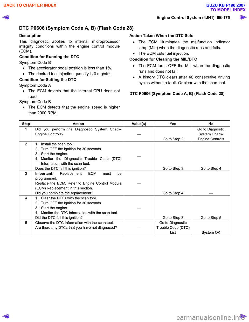
DTC P0606 (Symptom Code A, B) (Flash Code 28)
Description
This diagnostic applies to internal microprocesso
r
integrity conditions within the engine control module
(ECM).
Condition for Running the DTC
Symptom Code B • The accelerator pedal position is less than 1%.
• The desired fuel injection quantity is 0 mg/strk.
Condition for Setting the DTC
Symptom Code A • The ECM detects that the internal CPU does not
react.
Symptom Code B
• The ECM detects that the engine speed is highe
r
than 2000 RPM.
Action Taken When the DTC Sets
• The ECM illuminates the malfunction indicato
r
lamp (MIL) when the diagnostic runs and fails.
• The ECM cuts fuel injection.
Condition for Clearing the MIL/DTC
• The ECM turns OFF the MIL when the diagnostic
runs and does not fail.
• A history DTC clears after 40 consecutive driving
cycles without a fault. Or clear with the scan tool.
DTC P0606 (Symptom Code A, B) (Flash Code 28)
Step Action Value(s) Yes No
1 Did you perform the Diagnostic System Check-
Engine Controls?
Go to Step 2 Go to Diagnostic
System Check-
Engine Controls
2 1. Install the scan tool. 2. Turn OFF the ignition for 30 seconds.
3. Start the engine.
4. Monitor the Diagnostic Trouble Code (DTC) Information with the scan tool.
Does the DTC fail this ignition?
Go to Step 3 Go to Step 4
3 Important: Replacement ECM must be
programmed.
Replace the ECM. Refer to Engine Control Module
(ECM) Replacement in this section.
Did you complete the replacement?
Go to Step 4
4 1. Clear the DTCs with the scan tool.
2. Turn OFF the ignition for 30 seconds.
3. Start the engine.
4. Monitor the DTC Information with the scan tool.
Did the DTC fail this ignition?
Go to Step 3 Go to Step 5
5 Observe the DTC Information with the scan tool. Are there any DTCs that you have not diagnosed? Go to Diagnostic
Trouble Code (DTC) List System OK
BACK TO CHAPTER INDEX
TO MODEL INDEX
ISUZU KB P190 2007
Page 1210 of 6020
6E-176 Engine Control System (4JH1)
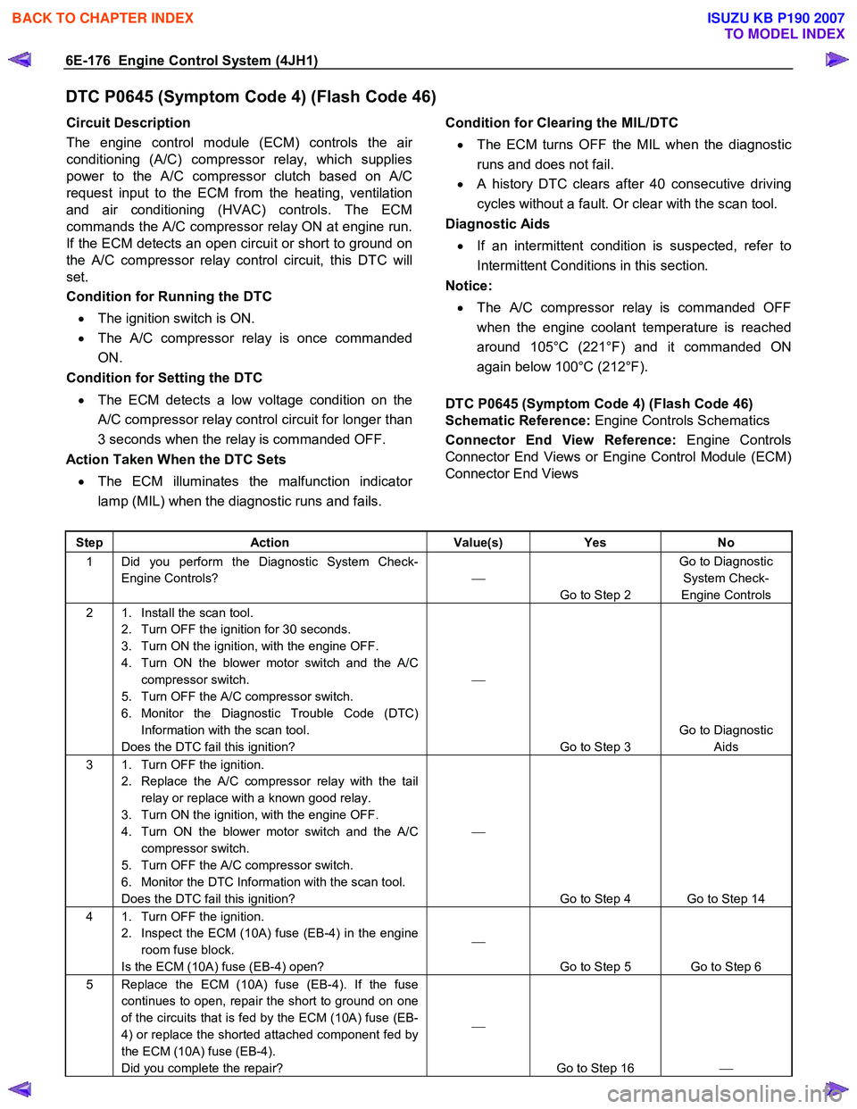
DTC P0645 (Symptom Code 4) (Flash Code 46)
Circuit Description
The engine control module (ECM) controls the ai
r
conditioning (A/C) compressor relay, which supplies
power to the A/C compressor clutch based on A/C
request input to the ECM from the heating, ventilation
and air conditioning (HVAC) controls. The ECM
commands the A/C compressor relay ON at engine run.
If the ECM detects an open circuit or short to ground on
the A/C compressor relay control circuit, this DTC will
set.
Condition for Running the DTC
• The ignition switch is ON.
• The A/C compressor relay is once commanded
ON.
Condition for Setting the DTC
• The ECM detects a low voltage condition on the
A/C compressor relay control circuit for longer than
3 seconds when the relay is commanded OFF.
Action Taken When the DTC Sets
• The ECM illuminates the malfunction indicato
r
lamp (MIL) when the diagnostic runs and fails.
Condition for Clearing the MIL/DTC
• The ECM turns OFF the MIL when the diagnostic
runs and does not fail.
• A history DTC clears after 40 consecutive driving
cycles without a fault. Or clear with the scan tool.
Diagnostic Aids
• If an intermittent condition is suspected, refer to
Intermittent Conditions in this section.
Notice:
• The A/C compressor relay is commanded OFF
when the engine coolant temperature is reached
around 105°C (221°F) and it commanded ON
again below 100°C (212°F).
DTC P0645 (Symptom Code 4) (Flash Code 46)
Schematic Reference: Engine Controls Schematics
Connector End View Reference: Engine Controls
Connector End Views or Engine Control Module (ECM)
Connector End Views
Step Action Value(s) Yes No
1 Did you perform the Diagnostic System Check-
Engine Controls?
Go to Step 2 Go to Diagnostic
System Check-
Engine Controls
2 1. Install the scan tool. 2. Turn OFF the ignition for 30 seconds.
3. Turn ON the ignition, with the engine OFF.
4. Turn ON the blower motor switch and the A/C compressor switch.
5. Turn OFF the A/C compressor switch.
6. Monitor the Diagnostic Trouble Code (DTC) Information with the scan tool.
Does the DTC fail this ignition?
Go to Step 3 Go to Diagnostic
Aids
3 1. Turn OFF the ignition. 2. Replace the A/C compressor relay with the tail relay or replace with a known good relay.
3. Turn ON the ignition, with the engine OFF.
4. Turn ON the blower motor switch and the A/C compressor switch.
5. Turn OFF the A/C compressor switch.
6. Monitor the DTC Information with the scan tool.
Does the DTC fail this ignition?
Go to Step 4 Go to Step 14
4 1. Turn OFF the ignition. 2. Inspect the ECM (10A) fuse (EB-4) in the engine room fuse block.
Is the ECM (10A) fuse (EB-4) open?
Go to Step 5 Go to Step 6
5 Replace the ECM (10A) fuse (EB-4). If the fuse continues to open, repair the short to ground on one
of the circuits that is fed by the ECM (10A) fuse (EB-
4) or replace the shorted attached component fed by
the ECM (10A) fuse (EB-4).
Did you complete the repair?
Go to Step 16
BACK TO CHAPTER INDEX
TO MODEL INDEX
ISUZU KB P190 2007
Page 1212 of 6020

6E-178 Engine Control System (4JH1)
Step Action Value(s) Yes No
15 Important: Replacement ECM must be
programmed.
Replace the ECM. Refer to Engine Control Module
(ECM) Replacement in this section.
Did you complete the replacement?
Go to Step 16
16 1. Reconnect all previously disconnected fuse,
relay or harness connector(s).
2. Clear the DTCs with the scan tool.
3. Turn OFF the ignition for 30 seconds.
4. Turn ON the ignition, with the engine OFF.
5. Turn ON the blower motor switch and the A/C compressor switch.
6. Turn OFF the A/C compressor switch.
7. Monitor the DTC Information with the scan tool.
Does the DTC fail this ignition?
Go to Step 3 Go to Step 17
17 Observe the DTC Information with the scan tool. Are there any DTCs that you have not diagnosed? Go to Diagnostic
Trouble Code (DTC) List System OK
BACK TO CHAPTER INDEX
TO MODEL INDEX
ISUZU KB P190 2007
Page 1213 of 6020
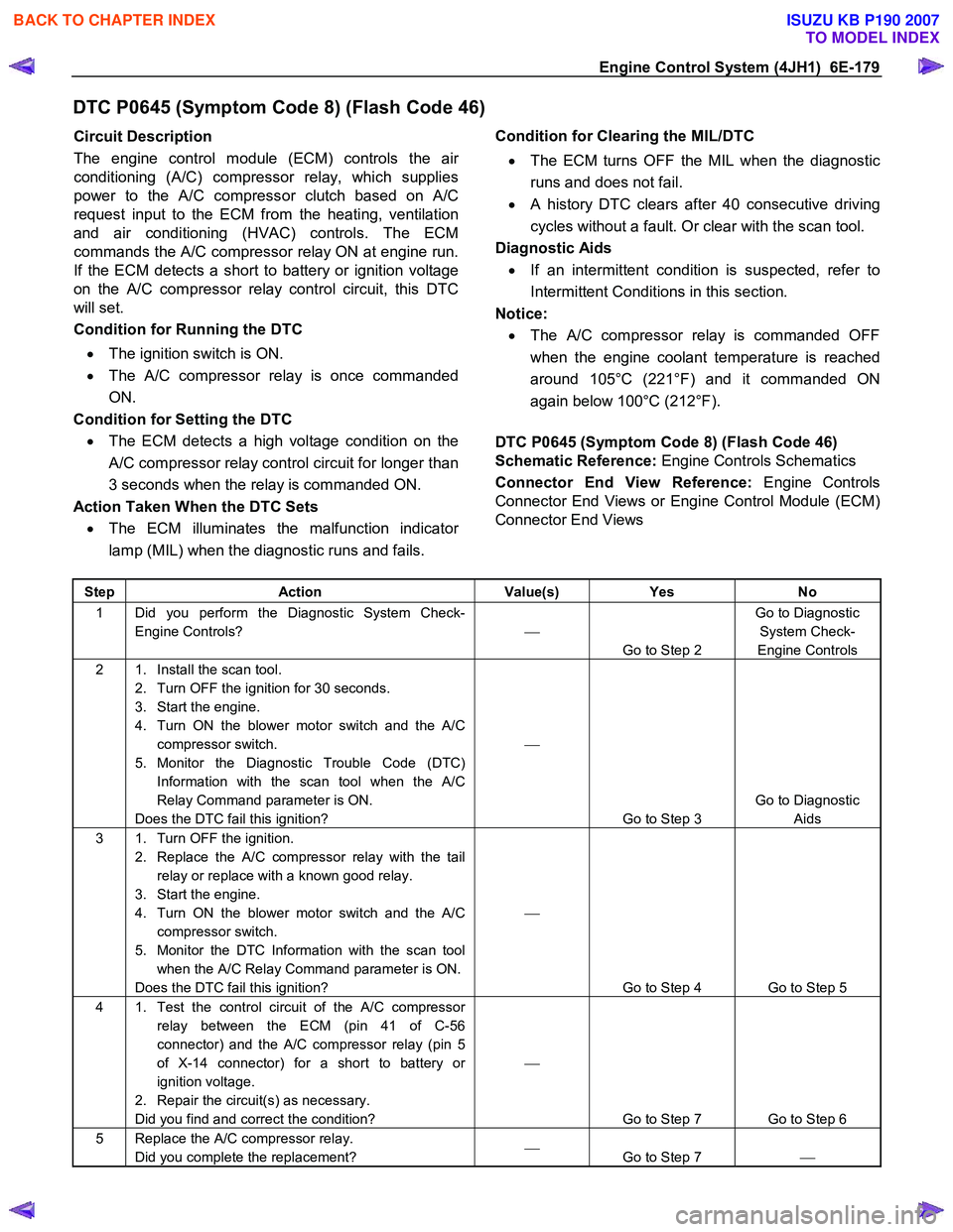
Engine Control System (4JH1) 6E-179
DTC P0645 (Symptom Code 8) (Flash Code 46)
Circuit Description
The engine control module (ECM) controls the ai
r
conditioning (A/C) compressor relay, which supplies
power to the A/C compressor clutch based on A/C
request input to the ECM from the heating, ventilation
and air conditioning (HVAC) controls. The ECM
commands the A/C compressor relay ON at engine run.
If the ECM detects a short to battery or ignition voltage
on the A/C compressor relay control circuit, this DTC
will set.
Condition for Running the DTC
• The ignition switch is ON.
• The A/C compressor relay is once commanded
ON.
Condition for Setting the DTC • The ECM detects a high voltage condition on the
A/C compressor relay control circuit for longer than
3 seconds when the relay is commanded ON.
Action Taken When the DTC Sets • The ECM illuminates the malfunction indicato
r
lamp (MIL) when the diagnostic runs and fails.
Condition for Clearing the MIL/DTC
• The ECM turns OFF the MIL when the diagnostic
runs and does not fail.
• A history DTC clears after 40 consecutive driving
cycles without a fault. Or clear with the scan tool.
Diagnostic Aids • If an intermittent condition is suspected, refer to
Intermittent Conditions in this section.
Notice: • The A/C compressor relay is commanded OFF
when the engine coolant temperature is reached
around 105°C (221°F) and it commanded ON
again below 100°C (212°F).
DTC P0645 (Symptom Code 8) (Flash Code 46)
Schematic Reference: Engine Controls Schematics
Connector End View Reference: Engine Controls
Connector End Views or Engine Control Module (ECM)
Connector End Views
Step Action Value(s) Yes No
1 Did you perform the Diagnostic System Check-
Engine Controls?
Go to Step 2 Go to Diagnostic
System Check-
Engine Controls
2 1. Install the scan tool. 2. Turn OFF the ignition for 30 seconds.
3. Start the engine.
4. Turn ON the blower motor switch and the A/C compressor switch.
5. Monitor the Diagnostic Trouble Code (DTC) Information with the scan tool when the A/C
Relay Command parameter is ON.
Does the DTC fail this ignition?
Go to Step 3 Go to Diagnostic
Aids
3 1. Turn OFF the ignition. 2. Replace the A/C compressor relay with the tail relay or replace with a known good relay.
3. Start the engine.
4. Turn ON the blower motor switch and the A/C compressor switch.
5. Monitor the DTC Information with the scan tool when the A/C Relay Command parameter is ON.
Does the DTC fail this ignition?
Go to Step 4 Go to Step 5
4 1. Test the control circuit of the A/C compressor relay between the ECM (pin 41 of C-56
connector) and the A/C compressor relay (pin 5
of X-14 connector) for a short to battery or
ignition voltage.
2. Repair the circuit(s) as necessary.
Did you find and correct the condition?
Go to Step 7 Go to Step 6
5 Replace the A/C compressor relay. Did you complete the replacement?
Go to Step 7
BACK TO CHAPTER INDEX
TO MODEL INDEX
ISUZU KB P190 2007
Page 1214 of 6020
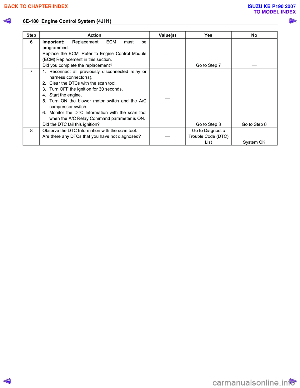
6E-180 Engine Control System (4JH1)
Step Action Value(s) Yes No
6 Important: Replacement ECM must be
programmed.
Replace the ECM. Refer to Engine Control Module
(ECM) Replacement in this section.
Did you complete the replacement?
Go to Step 7
7 1. Reconnect all previously disconnected relay or
harness connector(s).
2. Clear the DTCs with the scan tool.
3. Turn OFF the ignition for 30 seconds.
4. Start the engine.
5. Turn ON the blower motor switch and the A/C compressor switch.
6. Monitor the DTC Information with the scan tool when the A/C Relay Command parameter is ON.
Did the DTC fail this ignition?
Go to Step 3 Go to Step 8
8 Observe the DTC Information with the scan tool. Are there any DTCs that you have not diagnosed? Go to Diagnostic
Trouble Code (DTC) List System OK
BACK TO CHAPTER INDEX
TO MODEL INDEX
ISUZU KB P190 2007
Page 1215 of 6020
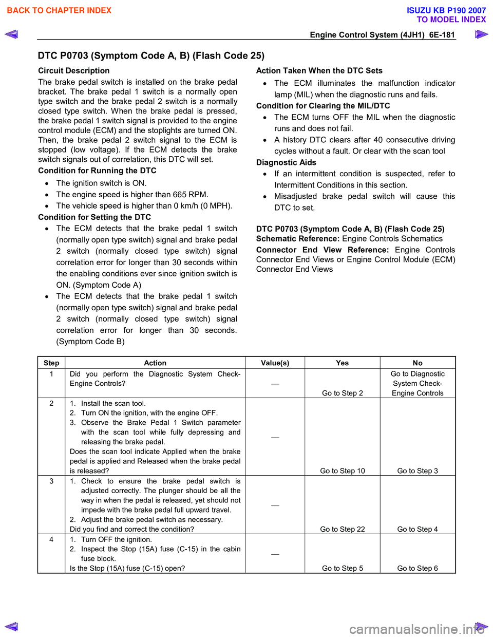
Engine Control System (4JH1) 6E-181
DTC P0703 (Symptom Code A, B) (Flash Code 25)
Circuit Description
The brake pedal switch is installed on the brake pedal
bracket. The brake pedal 1 switch is a normally open
type switch and the brake pedal 2 switch is a normally
closed type switch. W hen the brake pedal is pressed,
the brake pedal 1 switch signal is provided to the engine
control module (ECM) and the stoplights are turned ON.
Then, the brake pedal 2 switch signal to the ECM is
stopped (low voltage). If the ECM detects the brake
switch signals out of correlation, this DTC will set.
Condition for Running the DTC
• The ignition switch is ON.
• The engine speed is higher than 665 RPM.
• The vehicle speed is higher than 0 km/h (0 MPH).
Condition for Setting the DTC • The ECM detects that the brake pedal 1 switch
(normally open type switch) signal and brake pedal
2 switch (normally closed type switch) signal
correlation error for longer than 30 seconds within
the enabling conditions ever since ignition switch is
ON. (Symptom Code A)
• The ECM detects that the brake pedal 1 switch
(normally open type switch) signal and brake pedal
2 switch (normally closed type switch) signal
correlation error for longer than 30 seconds.
(Symptom Code B)
Action Taken When the DTC Sets
• The ECM illuminates the malfunction indicato
r
lamp (MIL) when the diagnostic runs and fails.
Condition for Clearing the MIL/DTC • The ECM turns OFF the MIL when the diagnostic
runs and does not fail.
• A history DTC clears after 40 consecutive driving
cycles without a fault. Or clear with the scan tool
Diagnostic Aids • If an intermittent condition is suspected, refer to
Intermittent Conditions in this section.
• Misadjusted brake pedal switch will cause this
DTC to set.
DTC P0703 (Symptom Code A, B) (Flash Code 25)
Schematic Reference: Engine Controls Schematics
Connector End View Reference: Engine Controls
Connector End Views or Engine Control Module (ECM)
Connector End Views
Step Action Value(s) Yes No
1 Did you perform the Diagnostic System Check-
Engine Controls?
Go to Step 2 Go to Diagnostic
System Check-
Engine Controls
2 1. Install the scan tool. 2. Turn ON the ignition, with the engine OFF.
3. Observe the Brake Pedal 1 Switch parameter with the scan tool while fully depressing and
releasing the brake pedal.
Does the scan tool indicate Applied when the brake
pedal is applied and Released when the brake pedal
is released?
Go to Step 10 Go to Step 3
3 1. Check to ensure the brake pedal switch is adjusted correctly. The plunger should be all the
way in when the pedal is released, yet should not
impede with the brake pedal full upward travel.
2. Adjust the brake pedal switch as necessary.
Did you find and correct the condition?
Go to Step 22 Go to Step 4
4 1. Turn OFF the ignition. 2. Inspect the Stop (15A) fuse (C-15) in the cabin fuse block.
Is the Stop (15A) fuse (C-15) open?
Go to Step 5 Go to Step 6
BACK TO CHAPTER INDEX
TO MODEL INDEX
ISUZU KB P190 2007