Page 2077 of 6020

ENGINE MECHANICAL (C24SE) 6A-63
OPERATIONS ON COOLING SYSTEM
Caution!
Before working with the cooling system, be sure to confirm that
the temperature of the engine is cooled down.
Failure to observe this may cause burn.
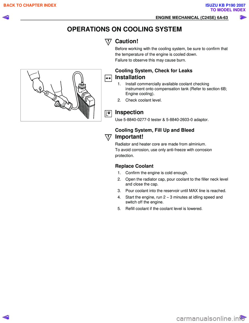
Cooling System, Check for Leaks
Installation
1. Install commercially available coolant checking instrument onto compensation tank (Refer to section 6B;
Engine cooling).
2. Check coolant level.
Inspection
Use 5-8840-0277-0 tester & 5-8840-2603-0 adaptor.
Cooling System, Fill Up and Bleed
Important!
Radiator and heater core are made from alminium.
To avoid corrosion, use only anti-freeze with corrosion
protection.
Replace Coolant
1. Confirm the engine is cold enough.
2. Open the radiator cap, pour coolant to the filler neck level and close the cap.
3. Pour coolant into the reservoir until MAX line is reached.
4. Start the engine, run 2 ∼ 3 minutes at idling speed and
switch off the engine.
5. Refill coolant if the coolant level is lowered.
BACK TO CHAPTER INDEX
TO MODEL INDEX
ISUZU KB P190 2007
Page 2078 of 6020

6A-64 ENGINE MECHANICAL (C24SE)
Important!
Do not loosen or open the radiator cap when coolant is hot.
Doing so may cause hot water or steam to splash out, resulting
in burn. W hen opening the radiator cap, be sure to confirm the
coolant is cold. Cover a thick cloth over the cap and loosen it
slowly to reduce pressure, then open the cap.
6. Close the radiator cap firmly and run the engine at approx. 2000 rpm. In addition, set the heater temperature
adjuster to the max position to circulate coolant in the
heater conduit system.
7. Confirm that the temperature gauge reads half or more of full scale and that the thermostat is activated.
Then continue idling 5 minutes more and switch off the
engine, and allow it to cool.
8. After the engine cools down, check the coolant level and refill it if necessary. W hen the level is lowered extremely,
check the coolant conduit system and reservoir hose for
leak.
9. Pour coolant into the reservoir to MAX level.
Refill Coolant
Important!
After closing the cooling system, let engine run warm until
thermostat opens (coolant approx. 92 °C/197.6F)
Inspection
Coolant level
Allow engine to cool. If necessary, refill coolant.
Check that cooling system self-bleeds during engine warming-
up phase.
Ignition Timing, Check
No Adjustment
BACK TO CHAPTER INDEX
TO MODEL INDEX
ISUZU KB P190 2007
Page 2080 of 6020
6A-66 ENGINE MECHANICAL (C24SE)
Installation
Follow the removal procedure in the reverse order to install the
radiator.
Thermostat
Removal
1. Remove water outlet nozzles with thermostat from thermostat housing.
2. Remove coolant hose and collect coolant.
Important!
Remove and Install thermostat only together with water outlet
nozzles.
Tighten (Torque)
W ater outlet nozzles to thermostat housing - 8 N ⋅m (0.8 kgf ⋅m)
Installation
1. Install coolant hose.
2. Fill cooling system and bleed according to the corresponding operation.
Water Pump
Removal
1. Remove lower hose band from pipe band and collect coolant.
2. Remove front toothed belt cover according to the corresponding operation.
3. Remove water pump from cylinder block after releasing tension on toothed belt.
Clean
Sealing surfaces
BACK TO CHAPTER INDEX
TO MODEL INDEX
ISUZU KB P190 2007
Page 2081 of 6020

ENGINE MECHANICAL (C24SE) 6A-67
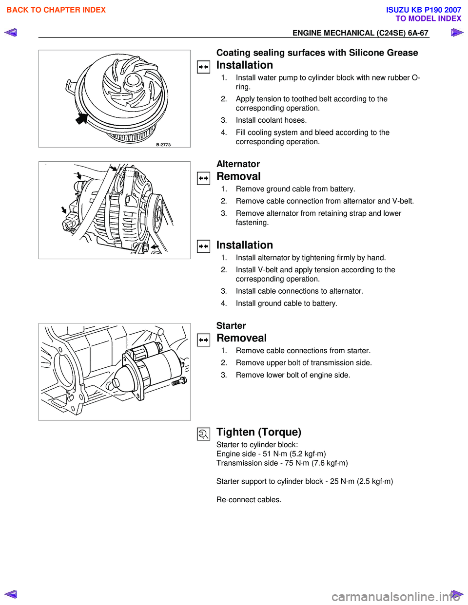
Coating sealing surfaces with Silicone Grease
Installation
1. Install water pump to cylinder block with new rubber O-ring.
2. Apply tension to toothed belt according to the corresponding operation.
3. Install coolant hoses.
4. Fill cooling system and bleed according to the corresponding operation.
Alternator
Removal
1. Remove ground cable from battery.
2. Remove cable connection from alternator and V-belt.
3. Remove alternator from retaining strap and lower fastening.
Installation
1. Install alternator by tightening firmly by hand.
2. Install V-belt and apply tension according to the corresponding operation.
3. Install cable connections to alternator.
4. Install ground cable to battery.
Starter
Removeal
1. Remove cable connections from starter.
2. Remove upper bolt of transmission side.
3. Remove lower bolt of engine side.
Tighten (Torque)
Starter to cylinder block:
Engine side - 51 N ⋅m (5.2 kgf ⋅m)
Transmission side - 75 N ⋅m (7.6 kgf ⋅m)
Starter support to cylinder block - 25 N ⋅m (2.5 kgf ⋅m)
Re-connect cables.
BACK TO CHAPTER INDEX
TO MODEL INDEX
ISUZU KB P190 2007
Page 2085 of 6020
ENGINE MECHANICAL (C24SE) 6A-71
Installation
(2.4L)
1. Install the ECM to the ECM bracket on engine.
2. Tighten the four screws to the bracket.
3. Connect the connector.
ECT
Removal
1. Remove wiring harness plug and coolant temperature sensor.
Tighten (Torque)
Temperature sensor to intake pipe - 10 N ⋅m (1.0 kgf ⋅m)
W iring harness plug to temperature sensor
Inspection
Coolant level
Idle Air Control (IAC) Valve
Removal
1. Remove wiring harness plug, hose clamps and idle speed adjuster.
Installation
1. Install idle speed adjuster, hose clamps and wiring harness plug.
Ignition Coil
Removal
1. Remove 2 bolts, plug and ignition coil.
Installation
1. Install ignition coil, plug and bolts.
BACK TO CHAPTER INDEX
TO MODEL INDEX
ISUZU KB P190 2007
Page 2091 of 6020

ENGINE MECHANICAL (C24SE) 6A-77
TECHNICAL DATA
SOHC Gasoline Engine C24SE
Engine Oil Viscosity
The following engine oils can be used:
A = single-grade oils
B = multigrade oils
C = easy run oils
depending on the outside temperature.
Engine Oil Quality
It is important that the following API and CCMC classes are
used:
Engines Single and multigrade oils Easy run oils
Petrol API-SF/CC, SF/CD, SG/CC,
SG/CD, CCMC/G4 API-SF/CC, SF/CD, SG/CD
CCMC-G5/PD2
Important!
CD engine oils designed by manufacturers specially for diesel
engines are not suitable for petrol engines, unless a sufficient
performance class for petrol engines (e.g. API-SF/CCMC-G4)
is also indicated.
Disposal.
Observe the relevant national regulations when disposing of
used oil.
Engine Oil Filling Quantities
Engine Model Initial filling
(litres) Filling quantity
with filter change* (litres) MIN to MAX
(litres)
2.4L 4.80 4.25 1.00
*Up to mark "MAX" on oil dipstick
Oil Pump
Backlash 0.1 to 0.2mm
Gaps in gears opposite housing 0.03 to 0.1mm
Oil pressure at idle speed Engine at operating temperature (>70°C oil and
approx. 80 °C coolant)
450 - 500 kpa
Oil drain plug M14 × 1.5
BACK TO CHAPTER INDEX
TO MODEL INDEX
ISUZU KB P190 2007
Page 2106 of 6020
6B-2 ENGINE COOLING
General Description
Legend
1 W ater Pump
2 Thermostat
3 Radiator
4 Reserve Tank 5 Coolant Distributor
6 Cylinder Block and Head
7 Throttle Body
8 Heater
The Cooling System is a pressurized type, where the water
pump, which is cambelt driven, forces the circulation of
the coolant through the cylinder block and head. The
thermostat regulates the flow of coolant between the
radiator and the bypass circuit. The heater is part of the
bypass circuit. The throttle body pre-heat is a separate
circuit which is not regulated by the thermostat. An oil
cooler may be fitted as part of this circuit.
BACK TO CHAPTER INDEX
TO MODEL INDEX
ISUZU KB P190 2007
Page 2108 of 6020
6B-4 ENGINE COOLING
Antifreeze Solution
• Calculating mixing ratio
Mixing ratio
= Antifreeze solution (Lit/gal.)
Antifreeze solution (Lit/gal.) + W ater (Lit/gal.)
NOTE: Antifreeze solution + W ater = Total cooling system
capacity.
• Total Cooling System Capacity
8Lit
• Mixing ratio
Check the specific gravity of engine coolant in the cooling system temperature ranges from 0 °C to 50 °C using a
suction type hydrometer, then determine the density of the
engine coolant by referring to the table.
NOTE: The LLC is 50% at all environment in order to prevent
the corrosion of cooling system parts.
BACK TO CHAPTER INDEX
TO MODEL INDEX
ISUZU KB P190 2007