2007 ISUZU KB P190 towing
[x] Cancel search: towingPage 3753 of 6020
Exhaust System – V6 Page 6F – 5
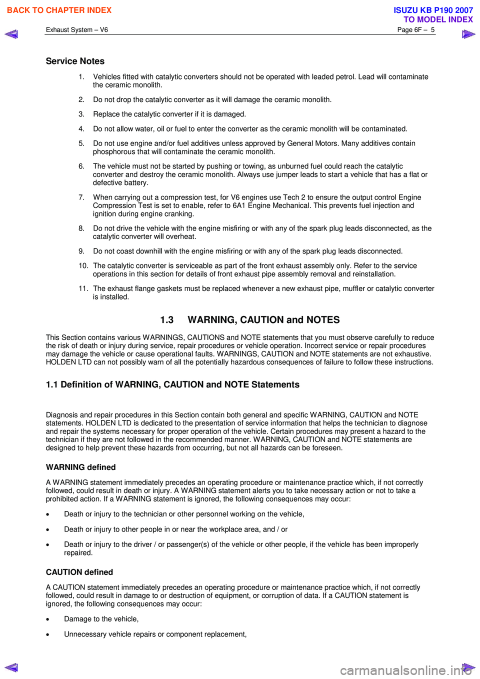
Service Notes
1. Vehicles fitted with catalytic converters should not be operated with leaded petrol. Lead will contaminate
the ceramic monolith.
2. Do not drop the catalytic converter as it will damage the ceramic monolith.
3. Replace the catalytic converter if it is damaged.
4. Do not allow water, oil or fuel to enter the converter as the ceramic monolith will be contaminated.
5. Do not use engine and/or fuel additives unless approved by General Motors. Many additives contain phosphorous that will contaminate the ceramic monolith.
6. The vehicle must not be started by pushing or towing, as unburned fuel could reach the catalytic converter and destroy the ceramic monolith. Always use jumper leads to start a vehicle that has a flat or
defective battery.
7. W hen carrying out a compression test, for V6 engines use Tech 2 to ensure the output control Engine Compression Test is set to enable, refer to 6A1 Engine Mechanical. This prevents fuel injection and
ignition during engine cranking.
8. Do not drive the vehicle with the engine misfiring or with any of the spark plug leads disconnected, as the catalytic converter will overheat.
9. Do not coast downhill with the engine misfiring or with any of the spark plug leads disconnected.
10. The catalytic converter is serviceable as part of the front exhaust assembly only. Refer to the service operations in this section for details of front exhaust pipe assembly removal and reinstallation.
11. The exhaust flange gaskets must be replaced whenever a new exhaust pipe, muffler or catalytic converter is installed.
1.3 WARNING, CAUTION and NOTES
This Section contains various W ARNINGS, CAUTIONS and NOTE statements that you must observe carefully to reduce
the risk of death or injury during service, repair procedures or vehicle operation. Incorrect service or repair procedures
may damage the vehicle or cause operational faults. W ARNINGS, CAUTION and NOTE statements are not exhaustive.
HOLDEN LTD can not possibly warn of all the potentially hazardous consequences of failure to follow these instructions.
1.1 Definition of WARNING, CAUTION and NOTE Statements
Diagnosis and repair procedures in this Section contain both general and specific W ARNING, CAUTION and NOTE
statements. HOLDEN LTD is dedicated to the presentation of service information that helps the technician to diagnose
and repair the systems necessary for proper operation of the vehicle. Certain procedures may present a hazard to the
technician if they are not followed in the recommended manner. W ARNING, CAUTION and NOTE statements are
designed to help prevent these hazards from occurring, but not all hazards can be foreseen.
WARNING defined
A W ARNING statement immediately precedes an operating procedure or maintenance practice which, if not correctly
followed, could result in death or injury. A W ARNING statement alerts you to take necessary action or not to take a
prohibited action. If a W ARNING statement is ignored, the following consequences may occur:
• Death or injury to the technician or other personnel working on the vehicle,
• Death or injury to other people in or near the workplace area, and / or
• Death or injury to the driver / or passenger(s) of the vehicle or other people, if the vehicle has been improperly
repaired.
CAUTION defined
A CAUTION statement immediately precedes an operating procedure or maintenance practice which, if not correctly
followed, could result in damage to or destruction of equipment, or corruption of data. If a CAUTION statement is
ignored, the following consequences may occur:
• Damage to the vehicle,
• Unnecessary vehicle repairs or component replacement,
BACK TO CHAPTER INDEX
TO MODEL INDEX
ISUZU KB P190 2007
Page 3768 of 6020
Automatic Transmission – 4L60E – General Information Page 7C1–8
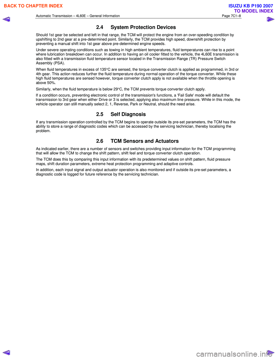
2.4 System Protection Devices
Should 1st gear be selected and left in that range, the TCM will protect the engine from an over-speeding condition by
upshifting to 2nd gear at a pre-determined point. Similarly, the TCM provides high speed, downshift protection by
preventing a manual shift into 1st gear above pre-determined engine speeds.
Under severe operating conditions such as towing in high ambient temperatures, fluid temperatures can rise to a point
where lubrication breakdown can occur. In addition to having an oil cooler fitted to the vehicle, the 4L60E transmission is
also fitted with a transmission fluid temperature sensor located in the Transmission Range (TR) Pressure Switch
Assembly (PSA).
When fluid temperatures in excess of 135 °C are sensed, the torque converter clutch is applied as programmed, in 3rd or
4th gear. This action reduces further the fluid temperature during normal operation of the torque converter. While these
high fluid temperatures are sensed however, torque converter clutch apply is not available when the throttle opening is
above 50%.
Similarly, when the fluid temperature is below 29 °C, the TCM prevents torque converter clutch apply.
If a condition occurs, preventing electronic control of the transmission's functions, a 'Fail Safe' mode will default the
transmission to 3rd gear when either Drive or 3 is selected, applying also maximum line pressure. W hile in this mode, the
vehicle operator can still manually select 2, 1, Reverse, Park or Neutral, should the need arise.
2.5 Self Diagnosis
If any transmission operation controlled by the TCM begins to operate outside its pre-set parameters, the TCM has the
ability to store a range of diagnostic codes which can be accessed by the servicing technician, thereby localising the
problem.
2.6 TCM Sensors and Actuators
As indicated earlier, there are a number of sensors and switches providing input information for the TCM programming
that will allow the TCM to change the shift pattern, shift feel and torque converter clutch operation.
The TCM does this by comparing this input information with its predetermined values on shift pattern, fluid pressure
maps, shift duration parameters, extreme heat protection programming and adaptive controls.
In addition, each input signal and output actuator operation is also monitored and if outside its pre-set parameters, a
diagnostic code is logged for future reference by the servicing technician.
BACK TO CHAPTER INDEX
TO MODEL INDEX
ISUZU KB P190 2007
Page 3820 of 6020
Automatic Transmission – 4L60E – Electrical Diagnosis Page 7C2–34
• The TCM records the operating conditions when the conditions for setting the DTC are met. The TCM stores this
information as Failure Records.
• The TCM stores DTC P0218 in TCM history.
Conditions for Clearing the DTC
• Tech 2 can clear the DTC.
• The TCM clears the DTC from TCM history if the vehicle completes 40 warm-up cycles without a non-emission
related diagnostic fault occurring.
• The TCM cancels the DTC default actions when the fault no longer exists and the DTC passes.
Diagnostic Aids
• Tech 2’s Transmission Fluid Temp. should rise steadily to a normal operating temperature, then stabilise.
• Ask about the customer's driving habits, trailer towing, etc. Trailer towing should occur in D3.
• Refer to Symptoms - Automatic Transmission in 7C3 Automatic Transmission – 4L60E – Hydraulic and Mechanical
Diagnosis.
Test Description
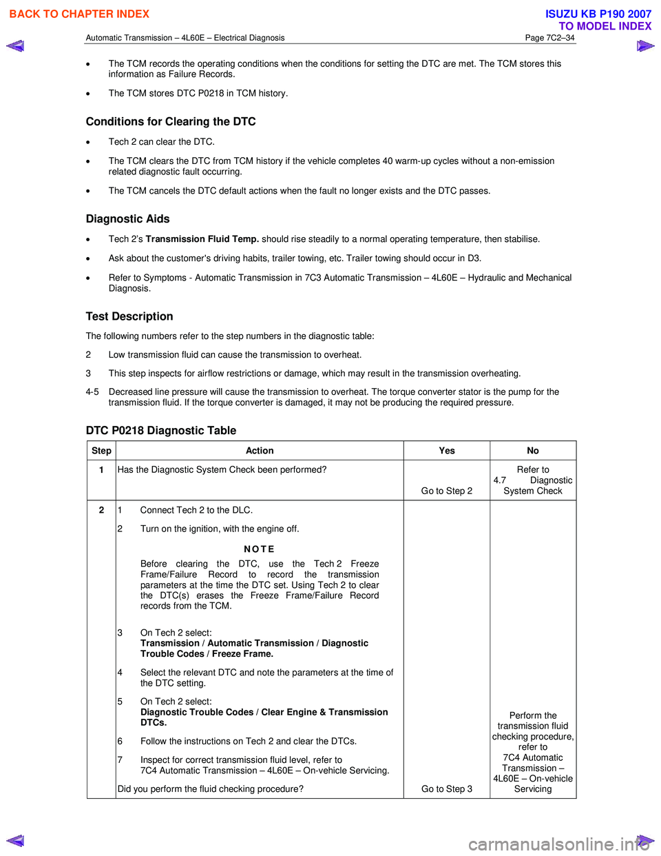
The following numbers refer to the step numbers in the diagnostic table:
2 Low transmission fluid can cause the transmission to overheat.
3 This step inspects for airflow restrictions or damage, which may result in the transmission overheating.
4-5 Decreased line pressure will cause the transmission to overheat. The torque converter stator is the pump for the transmission fluid. If the torque converter is damaged, it may not be producing the required pressure.
DTC P0218 Diagnostic Table
Step Action Yes No
1 Has the Diagnostic System Check been performed?
Go to Step 2 Refer to
4.7 Diagnostic System Check
2 1 Connect Tech 2 to the DLC.
2 Turn on the ignition, with the engine off.
NOTE
Before clearing the DTC, use the Tech 2 Freeze
Frame/Failure Record to record the transmission
parameters at the time the DTC set. Using Tech 2 to clear
the DTC(s) erases the Freeze Frame/Failure Record
records from the TCM.
3 On Tech 2 select: Transmission / Automatic Transmission / Diagnostic
Trouble Codes / Freeze Frame.
4 Select the relevant DTC and note the parameters at the time of the DTC setting.
5 On Tech 2 select:
Diagnostic Trouble Codes / Clear Engine & Transmission
DTCs.
6 Follow the instructions on Tech 2 and clear the DTCs.
7 Inspect for correct transmission fluid level, refer to 7C4 Automatic Transmission – 4L60E – On-vehicle Servicing.
Did you perform the fluid checking procedure? Go to Step 3 Perform the
transmission fluid
checking procedure, refer to
7C4 Automatic
Transmission –
4L60E – On-vehicle Servicing
BACK TO CHAPTER INDEX
TO MODEL INDEX
ISUZU KB P190 2007
Page 3831 of 6020
Automatic Transmission – 4L60E – Electrical Diagnosis Page 7C2–45
Diagnostic Aids
• Tech 2 displays the transmission fluid temperature in degrees. After the transmission is operating, the fluid
temperature should rise steadily to a normal operating temperature, then stabilise.
• Verify the customer's driving habits, trailer towing, etc. Trailer towing should occur in D3.
Test Description
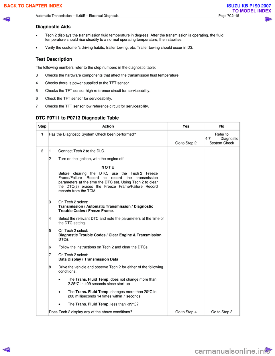
The following numbers refer to the step numbers in the diagnostic table:
3 Checks the hardware components that affect the transmission fluid temperature.
4 Checks there is power supplied to the TFT sensor.
5 Checks the TFT sensor high reference circuit for serviceability.
6 Check the TFT sensor for serviceability.
7 Checks the TFT sensor low reference circuit for serviceability.
DTC P0711 to P0713 Diagnostic Table
Step Action Yes No
1 Has the Diagnostic System Check been performed?
Go to Step 2 Refer to
4.7 Diagnostic System Check
2 1 Connect Tech 2 to the DLC.
2 Turn on the ignition, with the engine off.
NOTE
Before clearing the DTC, use the Tech 2 Freeze
Frame/Failure Record to record the transmission
parameters at the time the DTC set. Using Tech 2 to clear
the DTC(s) erases the Freeze Frame/Failure Record
records from the TCM.
3 On Tech 2 select: Transmission / Automatic Transmission / Diagnostic
Trouble Codes / Freeze Frame.
4 Select the relevant DTC and note the parameters at the time of the DTC setting.
5 On Tech 2 select:
Diagnostic Trouble Codes / Clear Engine & Transmission
DTCs.
6 Follow the instructions on Tech 2 and clear the DTCs.
7 On Tech 2 select: Data Display / Transmission Data
8 Drive the vehicle and observe Tech 2 for either of the following conditions:
• The Trans. Fluid Temp . does not change more than
2.25°C in 409 seconds since start-up
• The Trans. Fluid Temp . changes more than 20°C in
200 milliseconds 14 times within 7 seconds
• The Trans. Fluid Temp . less than -39°C?
Does Tech 2 display any of the above conditions? Go to Step 4 Go to Step 3
BACK TO CHAPTER INDEX
TO MODEL INDEX
ISUZU KB P190 2007
Page 3918 of 6020
Automatic Transmission – 4L60E – On-vehicle Servicing Page 7C4–5
2 Maintenance Operations
2.1 Transmission Fluid
When adding or changing the transmission fluid, use only the recommended automatic transmission fluid, refer to
0B Maintenance and Lubrication.
For the automatic transmission fluid diagnosis, refer to 7C3 Automatic Transmission – 4L60E – Hydraulic and
Mechanical Diagnosis.
Transmission Fluid Colour
New transmission fluid is red in colour due to a dye that is added to the fluid so it can be distinguished from other oils and
lubricants. The red dye is not permanent and as such, is not an indicator of the quality of the fluid.
As the vehicle is driven the transmission fluid will quickly look darker in colour and appear to be a light brown. A dark
brown colour with a distinctively burnt odour may indicate fluid deterioration and the need for fluid replacement.
NOTE
A dark brown fluid colour observed, coupled with
a reported delayed shift pattern may only indicate
that fluid replacement is required. This is not a
definite indication of a potential transmission
failure.
Transmission Fluid Level
NOTE
Carry out this operation with the transmission at
normal operating temperature (82 – 94°C), as the
temperature greatly affects the fluid level.
1 Drive the vehicle for a distance of at least 25 km to bring the transmission up to normal operating temperature.
If the transmission is not at normal operating
temperature and the correct procedure is not
followed, the result could be a false reading of
the fluid level on the transmission fluid
indicator.
2 If the vehicle has been operated under any of the following conditions, switch the engine off and allow the transmission to cool for approximately thirty minutes:
• in high ambient temperatures above 32° C,
• at sustained high speeds,
• in heavy stop / start city traffic during hot weather, or
• towing.
3 Park the vehicle on level ground.
4 Move the gear selector to the Park position and apply the park brake.
5 Allow the engine to idle for 3 minutes with the accessories turned off.
BACK TO CHAPTER INDEX
TO MODEL INDEX
ISUZU KB P190 2007
Page 4378 of 6020
7A2-94 TRANSMISSION CONTROL SYSTEM (JR405E)
Temperature Sensitivity• An intermittent condition may occur when a component/ connection reaches
normal operating temperature. The condition may occur only when the
component/ connection is cold, or only when the component/ connection is hot.
• If the intermittent is related to heat, review the data for a relationship with the following:
- High ambient temperatures.
- Underhood/ engine generated heat.
- Circuit generated heat due to a poor connection, or high electrical load.
- Higher than normal load conditions, towing, etc.
• If the intermittent is related to cold, review the data for the following: - Low ambient temperatures-In extremely low temperatures, ice may form in a connection or component. Test for water intrusion.
- The condition only occurs on a cold start.
- The condition goes away when the vehicle warms up.
• Information from the customer may help to determine if the trouble follows a pattern that is temperature related.
Electromagnetic Interference (EMI) and
Electrical Noise Some electrical components/ circuits are sensitive to EMI or other types of electrical
noise. Inspect the following conditions:
• A misrouted harness that is too close to high voltage/ high current devices such as injection components, motors, generator etc. These components may
induce electrical noise on a circuit that could interfere with normal circuit
operation.
• Electrical system interference caused by a malfunctioning relay, or the TCM driven solenoid or switch. These conditions can cause a sharp electrical surge.
Normally, the problem will occur when the malfunctioning component is
operating.
• Improper installation of non-factory or aftermarket add on accessories such as lights, 2-way radios, amplifiers, electric motors, remote starters, alarm systems,
cell phones, etc. These accessories may lead to an emission related failure
while in use, but do not fail when the accessories are not in use.
• Test for any open diodes. Some relays may contain a clamping diode.
• Test the generator for a bad rectifier bridge that may be allowing AC noise into the electrical system.
Incorrect TCM Programming • There are only a few situations where reprogramming a TCM is appropriate:
- An ECM from another vehicle is installed.
- Revised software/ calibration files have been released for this vehicle.
Important: DO NOT reprogram the TCM with the SAME software/ calibration files
that are already present in the TCM. This is not an effective repair for any type of
driveability problem.
• Verify that the TCM contains the correct software/ calibration. If incorrect programming is found, reprogram the TCM with the most current software/
calibration.
Duplicating Failure Conditions • If none of the previous tests are successful, attempt to duplicate and/ or capture
the failure conditions.
• An alternate method is to drive the vehicle with the DMM connected to a suspected circuit. An abnormal reading on the DMM when the problem occurs,
may help you locate the problem.
Scan Tool Snapshot The scan tool can be set up to take a Snapshot of the parameters available via serial
data. The Snapshot function records live data over a period of time. The recorded
data can be played back and analyzed. The scan tool can also graph parameters
singly or in combinations of parameters for comparison. The Snapshot can be
triggered manually at the time the symptom is noticed, or set up in advance to trigger
when a DTC sets.
An abnormal value captured in the recorded data may point to a system or
component that needs to be investigated further.
Refer to the scan tool Users Guide for more information.
Checks
Action
BACK TO CHAPTER INDEX
TO MODEL INDEX
ISUZU KB P190 2007