2007 ISUZU KB P190 tire type
[x] Cancel search: tire typePage 1532 of 6020
ENGINE COOLING (4JK1/4JJ1) 6B-9
Inspection and Repair
The water pump is not disassembled type.
Make necessary parts replacement if extreme wear o
r
damage is found during inspection. Should any of the
following problems occur, the entire water pump
assembly must be replaced.
• Cracks in the water pump body.
• Coolant leakage from the sealed unit.
• Excessive radial play or abnormal noise in the fan
center when rotated by hand.
• Excessive thrust play in the fan center (Standard
play: less than 0.2 mm (0.0078 in)).
• Cracks or corrosion in the impeller.
Installation
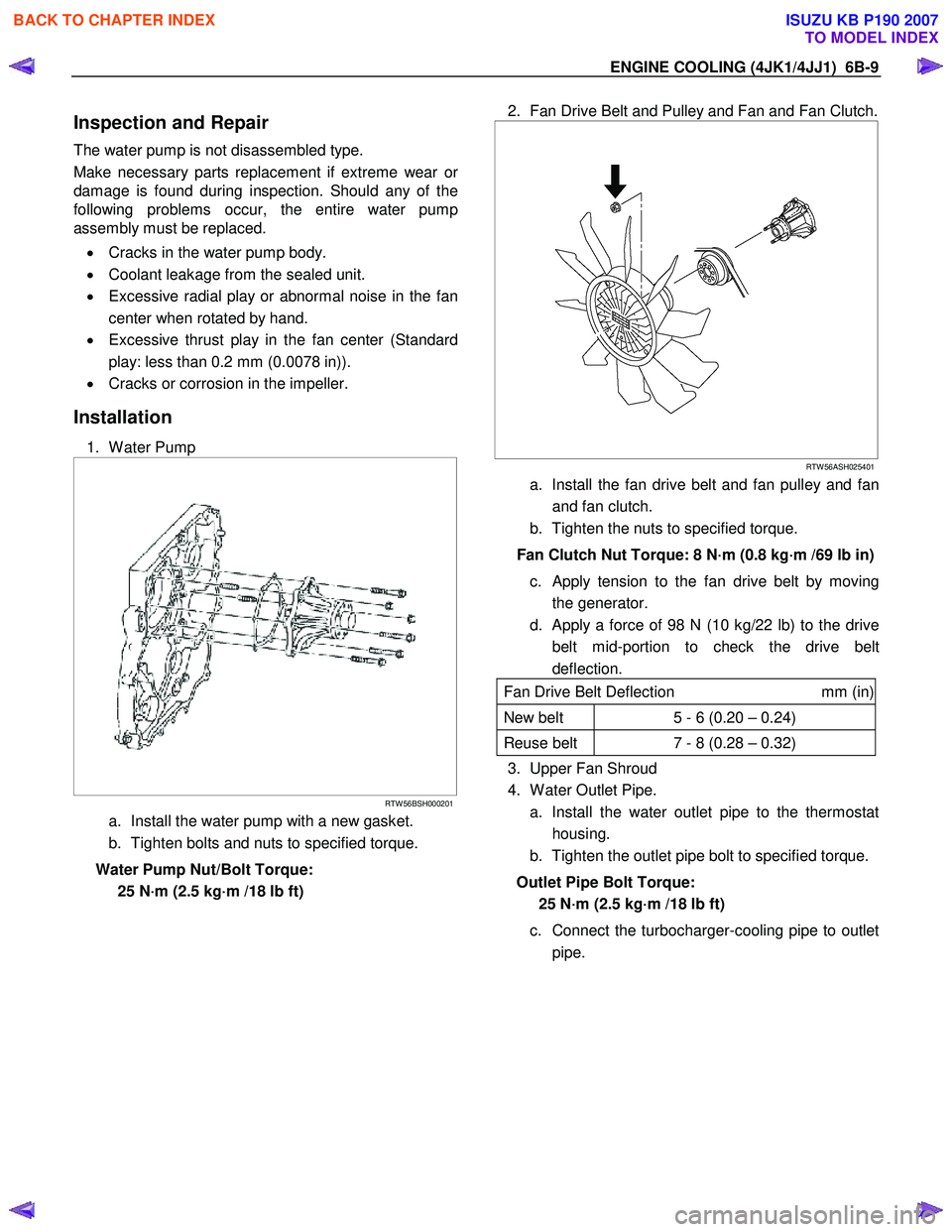
1. W ater Pump
RTW 56BSH000201
a. Install the water pump with a new gasket.
b. Tighten bolts and nuts to specified torque.
Water Pump Nut/Bolt Torque: 25 N·m (2.5 kg·m /18 lb ft)
2. Fan Drive Belt and Pulley and Fan and Fan Clutch.
RTW 56ASH025401
a. Install the fan drive belt and fan pulley and fan
and fan clutch.
b. Tighten the nuts to specified torque.
Fan Clutch Nut Torque: 8 N·m (0.8 kg·m /69 lb in) c. Apply tension to the fan drive belt by moving the generator.
d. Apply a force of 98 N (10 kg/22 lb) to the drive belt mid-portion to check the drive belt
deflection.
Fan Drive Belt Deflection mm (in)
New belt 5 - 6 (0.20 – 0.24)
Reuse belt 7 - 8 (0.28 – 0.32)
3. Upper Fan Shroud
4. W ater Outlet Pipe.
a. Install the water outlet pipe to the thermostat housing.
b. Tighten the outlet pipe bolt to specified torque.
Outlet Pipe Bolt Torque: 25 N·m (2.5 kg·m /18 lb ft)
c. Connect the turbocharger-cooling pipe to outlet pipe.
BACK TO CHAPTER INDEX
TO MODEL INDEX
ISUZU KB P190 2007
Page 1826 of 6020
ENGINE CONTROL SYSTEM (4JK1/4JJ1) 6E-209
DTC P0652 or P0653 (Flash Code 56)
Circuit Description
The ECM provides 5 volts reference voltage through
the reference circuit 2 to the following sensors:
• Accelerator pedal position (APP) sensor 2
• Fuel rail pressure (FRP) sensor
• Barometric pressure (BARO) sensor
• Camshaft position (CMP) sensor
• EGR position sensor
The 5 volts reference circuits are independent of each
other outside the ECM, but are bussed together inside
the ECM. Therefore, a short circuit condition on one 5
volts reference circuit affects the entire 5 volts
reference circuit 2. The ECM monitors the voltage on
the 5 volts reference circuit 2. If the ECM detects the
voltage is excessively low or high, DTC P0652 or
P0653 will set.
Condition for Running the DTC • The battery voltage is more than 6 volts.
• The ignition switch is ON.
Condition for Setting the DTC • The ECM detects that the 5 volts reference circuit 2 voltage is less than 4.7 volts. (DTC P0652)
• The ECM detects that the 5 volts reference circuit 2 voltage is more than 5.3 volts. (DTC P0653) Action Taken When the DTC Sets
• The ECM illuminates the MIL when the diagnostic runs and fails. Refer to DTC Type Definitions for
Action Taken When the DTC Sets - Type A.
• The ECM limits fuel injection quantity.
• The ECM inhibits pilot injection.
• The ECM inhibits EGR control.
• The ECM inhibits cruise control.
Condition for Clearing the DTC • Refer to DTC Type Definitions for Condition for Clearing the MIL/ DTC - Type A.
Diagnostic Aids • If an intermittent condition is suspected, refer to Intermittent Conditions in this section.
Notice: • If this DTC is present, the engine cranks but does not start.
Schematic Reference: Engine Controls Schematics
Connector End View Reference: Engine Controls
Connector End Views or ECM Connector End Views
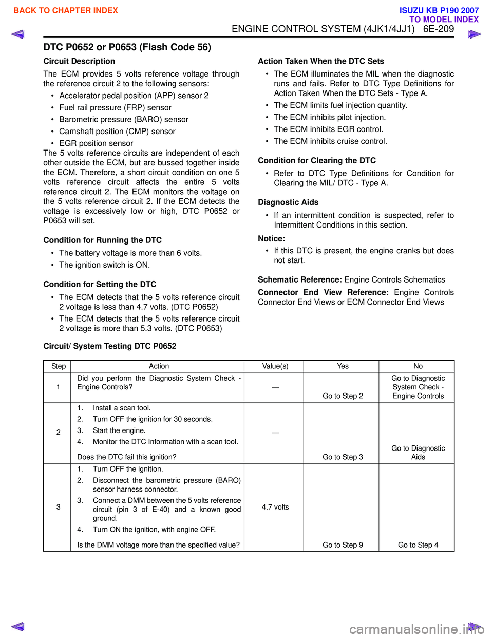
Circuit/ System Testing DTC P0652
Step Action Value(s)Yes No
1 Did you perform the Diagnostic System Check -
Engine Controls? —
Go to Step 2 Go to Diagnostic
System Check -
Engine Controls
2 1. Install a scan tool.
2. Turn OFF the ignition for 30 seconds.
3. Start the engine.
4. Monitor the DTC Information with a scan tool.
Does the DTC fail this ignition? —
Go to Step 3 Go to Diagnostic
Aids
3 1. Turn OFF the ignition.
2. Disconnect the barometric pressure (BARO) sensor harness connector.
3. Connect a DMM between the 5 volts reference circuit (pin 3 of E-40) and a known good
ground.
4. Turn ON the ignition, with engine OFF.
Is the DMM voltage more than the specified value? 4.7 volts
Go to Step 9 Go to Step 4
BACK TO CHAPTER INDEX
TO MODEL INDEX
ISUZU KB P190 2007
Page 1834 of 6020
ENGINE CONTROL SYSTEM (4JK1/4JJ1) 6E-217
DTC P0698 or P0699 (Flash Code 57)
Circuit Description
The ECM provides 5 volts reference voltage through
the reference circuit 3 to the following sensors:
• Accelerator pedal position (APP) sensor 3
• Boost pressure sensor
• Crankshaft position (CKP) sensor
• Intake throttle position sensor
The 5 volts reference circuits are independent of each
other outside the ECM, but are bussed together inside
the ECM. Therefore, a short circuit condition on one 5
volts reference circuit affects the entire 5 volts
reference circuit 3. The ECM monitors the voltage on
the 5 volts reference circuit 3. If the ECM detects the
voltage is excessively low or high, DTC P0698 or
P0699 will set.
Condition for Running the DTC • The battery voltage is more than 6 volts.
• The ignition switch is ON.
Condition for Setting the DTC • The ECM detects that the 5 volts reference circuit 3 voltage is less than 4.7 volts. (DTC P0698) • The ECM detects that the 5 volts reference circuit
3 voltage is less than 5.3 volts. (DTC P0699)
Action Taken When the DTC Sets • The ECM illuminates the MIL when the diagnostic runs and fails. Refer to DTC Type Definitions for
Action Taken When the DTC Sets - Type A.
• The ECM limits fuel injection quantity.
• The ECM inhibits pilot injection.
• The ECM inhibits EGR control.
• The ECM inhibits cruise control.
Condition for Clearing the DTC • Refer to DTC Type Definitions for Condition for Clearing the MIL/ DTC - Type A.
Diagnostic Aids • If an intermittent condition is suspected, refer to Intermittent Conditions in this section.
Engine Controls Schematics
Connector End View Reference: Engine Controls
Connector End Views or ECM Connector End Views
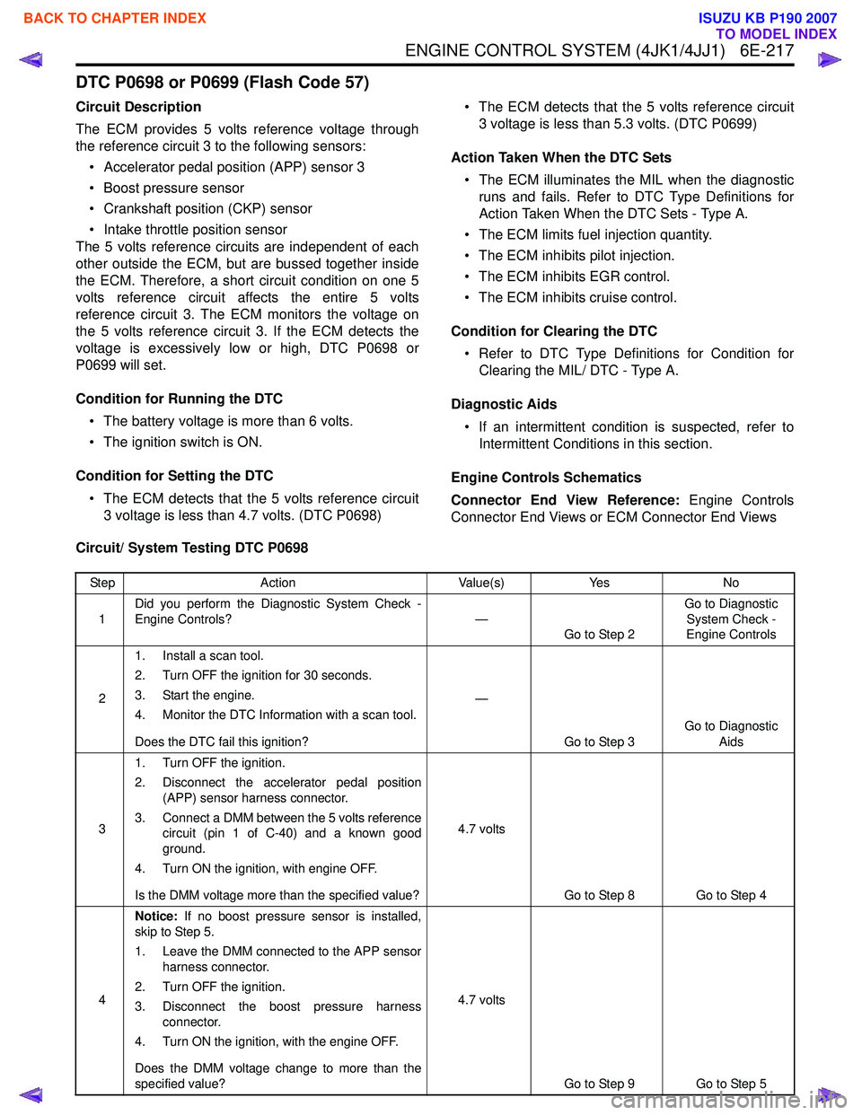
Circuit/ System Testing DTC P0698
Step Action Value(s)Yes No
1 Did you perform the Diagnostic System Check -
Engine Controls? —
Go to Step 2 Go to Diagnostic
System Check -
Engine Controls
2 1. Install a scan tool.
2. Turn OFF the ignition for 30 seconds.
3. Start the engine.
4. Monitor the DTC Information with a scan tool.
Does the DTC fail this ignition? —
Go to Step 3 Go to Diagnostic
Aids
3 1. Turn OFF the ignition.
2. Disconnect the accelerator pedal position (APP) sensor harness connector.
3. Connect a DMM between the 5 volts reference circuit (pin 1 of C-40) and a known good
ground.
4. Turn ON the ignition, with engine OFF.
Is the DMM voltage more than the specified value? 4.7 volts
Go to Step 8 Go to Step 4
4 Notice:
If no boost pressure sensor is installed,
skip to Step 5.
1. Leave the DMM connected to the APP sensor harness connector.
2. Turn OFF the ignition.
3. Disconnect the boost pressure harness connector.
4. Turn ON the ignition, with the engine OFF.
Does the DMM voltage change to more than the
specified value? 4.7 volts
Go to Step 9 Go to Step 5
BACK TO CHAPTER INDEX
TO MODEL INDEX
ISUZU KB P190 2007
Page 1958 of 6020
ENGINE CONTROL SYSTEM (4JK1/4JJ1) 6E-341
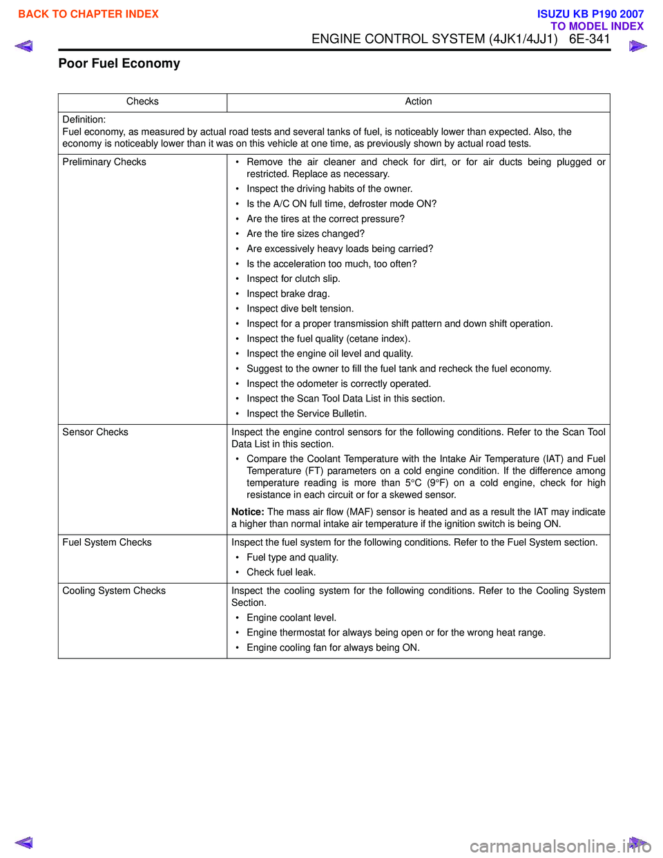
Poor Fuel Economy
ChecksAction
Definition:
Fuel economy, as measured by actual road tests and several tanks of fuel, is noticeably lower than expected. Also, the
economy is noticeably lower than it was on this vehicle at one time, as previously shown by actual road tests.
Preliminary Checks • Remove the air cleaner and check for dirt, or for air ducts being plugged or
restricted. Replace as necessary.
• Inspect the driving habits of the owner.
• Is the A/C ON full time, defroster mode ON?
• Are the tires at the correct pressure?
• Are the tire sizes changed?
• Are excessively heavy loads being carried?
• Is the acceleration too much, too often?
• Inspect for clutch slip.
• Inspect brake drag.
• Inspect dive belt tension.
• Inspect for a proper transmission shift pattern and down shift operation.
• Inspect the fuel quality (cetane index).
• Inspect the engine oil level and quality.
• Suggest to the owner to fill the fuel tank and recheck the fuel economy.
• Inspect the odometer is correctly operated.
• Inspect the Scan Tool Data List in this section.
• Inspect the Service Bulletin.
Sensor Checks Inspect the engine control sensors for the following conditions. Refer to the Scan Tool
Data List in this section.
• Compare the Coolant Temperature with the Intake Air Temperature (IAT) and Fuel Temperature (FT) parameters on a cold engine condition. If the difference among
temperature reading is more than 5 °C (9 °F) on a cold engine, check for high
resistance in each circuit or for a skewed sensor.
Notice: The mass air flow (MAF) sensor is heated and as a result the IAT may indicate
a higher than normal intake air temperature if the ignition switch is being ON.
Fuel System Checks Inspect the fuel system for the following conditions. Refer to the Fuel System section.
• Fuel type and quality.
• Check fuel leak.
Cooling System Checks Inspect the cooling system for the following conditions. Refer to the Cooling System
Section.
• Engine coolant level.
• Engine thermostat for always being open or for the wrong heat range.
• Engine cooling fan for always being ON.
BACK TO CHAPTER INDEX
TO MODEL INDEX
ISUZU KB P190 2007
Page 1966 of 6020
ENGINE CONTROL SYSTEM (4JK1/4JJ1) 6E-349
4. In order to get programming approval, the on-screen displays a message to user. Get
programming approval from the TIS 2000 using
the following procedure:
a. Connect a scan tool to the terminal that installed TIS 2000 with the latest software and
the hardware key is plugged into port.
b. Turn ON the scan tool and keep at title screen.
c. Launch the TIS application.
d. Select the Security Access at the main screen.
e. Highlight the “Tech 2” on the Diagnostic Tool Selection screen and click “Next”.
f. Click “Close” on the Security Access Enabled screen.
g. Turn OFF the scan tool.
h. Disconnect the scan tool from the terminal.
5. Install a scan tool to the vehicle.
6. Turn ON the ignition, with the engine OFF.
7. Select Diagnostics > appropriate vehicle identification > 4JK1 or 4JJ1 > Programming >
Program ECU.
8. Verify the VIN on the screen if programmed at previously described SPS. If not programmed or
incorrect VIN, input correct VIN.
9. Input 24 digits of each fuel injector ID code.
10. After complete the programming, turn OFF the ignition for 30 seconds.
11. Start the engine and let idle.
12. Inspect for a proper engine running condition and for no DTC's. Refer to the Diagnostic System
Check - Engine Controls if needed.
G. Supply Pump Relearn 1. Install a scan tool.
2. Start the engine and let idle until engine coolant temperature reads 65 °C (149 °F) or higher while
observing the Supply Pump Status parameter with
a scan tool. The scan tool parameter changes
status Not Learn > Learning > Learned.
3. If the ECM has correctly learned the fuel supply pump current adjustment, the Supply Pump Status
parameter on the scan tool will repeatedly indicate
Learning and Learned.Service Programming System (SPS)
Description
The service programming system (SPS) allows a
technician to program a control module through the
data link connector (DLC). The information transfer
circuit that is used at the DLC is the same serial data
circuit used by the scan tool for retrieving DTCs,
displaying data, clearing DTCs etc. This procedure
offers the ability to install software/ calibrations
matched to a particular vehicle.
Most control modules have two types of memory. The
software/ calibrations reside in the flash memory. The
two types of memory are listed below:
• Electrically Erasable Programmable Read Only Memory (EEPROM)
This type of memory allows selected portions of
memory to be programmed while other portions
remain unchanged.
Certain learned values reside in the EEPROM,
such as:
- The vehicle identification number (VIN)
- The software/ calibrations identification numbers
- The control module security information
• Flash Read Only Memory-Flash Memory Flash memory has increased memory storage
capacity. During programming, all information
within this type of memory is erased, and then
replaced with entirely new information.
Service Programming Methods
The two methods of programming an ECM are listed
below:
• Remote Programming
• Pass Thru Programming
For information on programming an ECM using one of
the methods listed above, refer to Service
Programming System (SPS) (Remote Procedure) or
Service Programming System (SPS) (Pass-Thru
Procedure).
Before Programming a Control Module
Important: DO NOT program an existing ECM with the
identical software/ calibration package. This procedure is not
a short cut to correct the driveability condition. This is an
ineffective repair. An ECM should only be programmed when
the following occurs:
• When a service procedure instructs you to replace the ECM.
• An updated software/ calibrations is released.
Ensure that the following conditions are met before
programming an ECM:
• The scan tool PCMCIA card is programmed with the latest software.
• The TIS 2000 is installed with the latest software.
BACK TO CHAPTER INDEX
TO MODEL INDEX
ISUZU KB P190 2007
Page 2139 of 6020
6D1-2 ENGINE ELECTRICAL
Battery
General Description
There are six battery fluid caps on top of the battery.
These are covered by a paper label.
The battery is completely sealed except for the six small vent
holes on the side. These vent holes permit the escape of small
amounts of gas generated by the battery.
This type of battery has the following advantages over
conventional batteries:
1. There is no need to add water during the entire service life
of the battery.
2. The battery protects itself against overcharging.
The battery will refuse to accept an extensive charge.
(A conventional battery will accept an excessive charge, resulting in gassing and loss of battery fluid.)
3. The battery is much less vulnerable to self discharge than a conventional type battery.
Service Precaution
CAUTION:
Always use the correct fastener in the proper location.
When you replace a fastener, use ONLY the exact part
number for that application. ISUZU will call out those
fasteners that require a replacement after removal. ISUZU
will also call out the fasteners that require thread lockers
or thread sealant. UNLESS OTHERWISE SPECIFIED, do
not use supplemental coatings (Paints, greases, or other
corrosion inhibitors) on threaded fasteners or fastener
joint interfaces. Generally, such coatings adversely affect
the fastener torque and the joint clamping force, and may
damage the fastener. When you install fasteners, use the
correct tightening sequence and specifications. Following
these instructions can help you avoid damage to parts
and systems.
BACK TO CHAPTER INDEX
TO MODEL INDEX
ISUZU KB P190 2007
Page 2146 of 6020
IGNITION SYSTEM 6D2-3
Spark Plug
Removal
1. Remove spark plugs.
Inspection and Repair
The spark plug affects entire engine performance and
therefore its inspection is very important.
• Check electrode and insulator for presence of cracks, and
replace if any.
• Check electrode for wear, and replace if necessary.
• Check gasket for damage, and replace if necessary.
• Measure insulation resistance with an ohmmeter, and
replace if faulty.
• Adjust spark plug gap to 1.0 - 1.1 mm (0.027 in) - 0.8 mm
(0.031 in).
• Check fuel and electrical systems if spark plug is extremely
dirty.
• Use spark plugs having low heat value (hot type plug) if fuel
and electrical systems are normal.
• Use spark plugs having high heat value (cold type plug) i
f
insulator and electrode are extremely burned.
Sooty Spark Plugs
Much deposit of carbon or oil on the electrode and insulator of
spark plug reduces the engine performance.
Possible causes:
• Too rich mixture
• Presence of oil in combustion chamber
• Incorrectly adjusted spark plug gap
Burning Electrodes
This fault is characterized by scorched or heavily oxidized
electrode or blistered insulator nose.
Possible causes:
• Too lean mixture
• Improper heat value
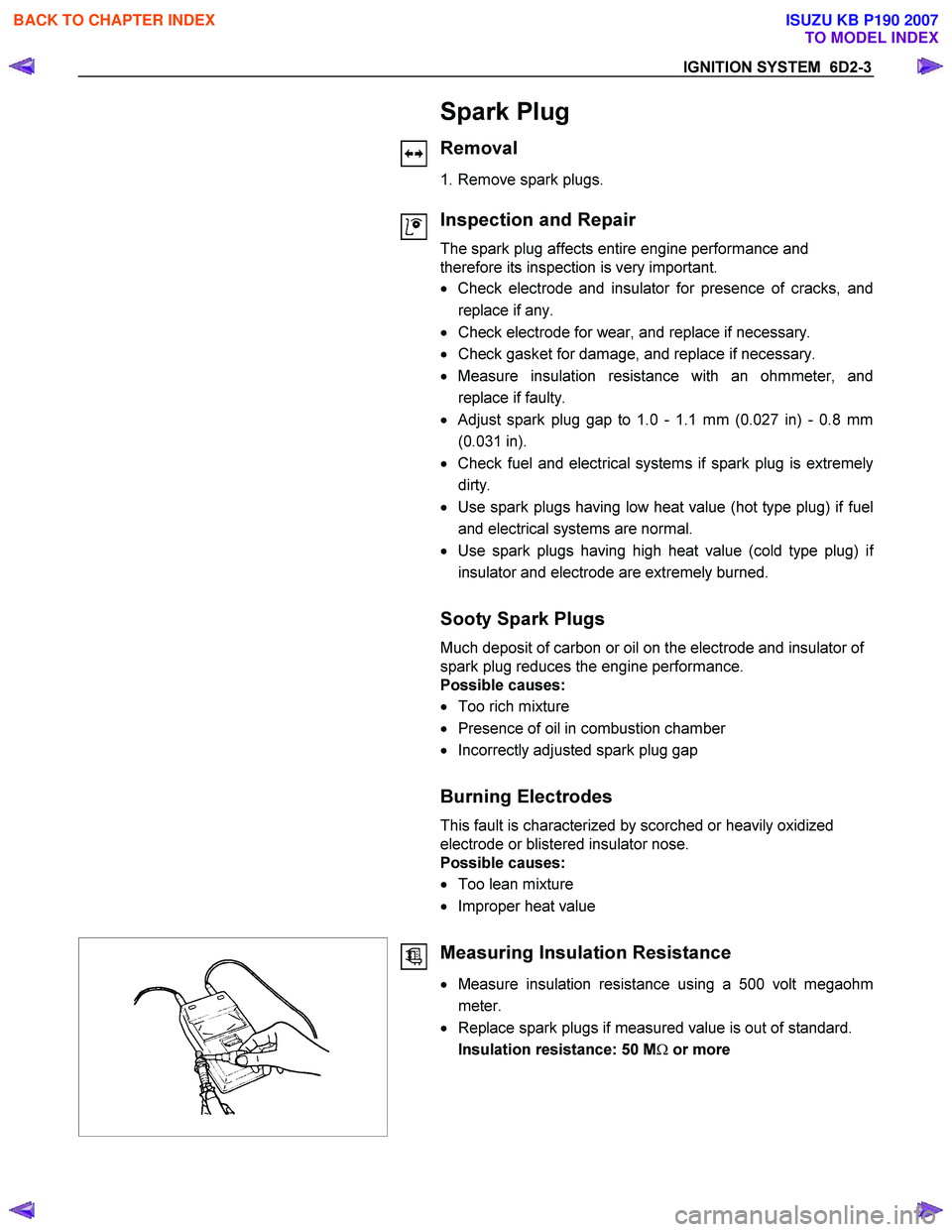
Measuring Insulation Resistance
• Measure insulation resistance using a 500 volt megaohm
meter.
• Replace spark plugs if measured value is out of standard.
Insulation resistance: 50 M Ω or more
BACK TO CHAPTER INDEX
TO MODEL INDEX
ISUZU KB P190 2007
Page 2519 of 6020
Engine Mechanical – V6 Page 6A1–40
Cause Correction
W orn valve guides and or valve stems. Inspect and repair valves and valve guides as required,
refer to 3.22 Cylinder Head Assembly.
W orn or damaged valve stem oil seal. Replace valve stem oil seals as required, refer to 3.22
Cylinder Head Assembly.
Piston rings broken, worn or not seated correctly. Allowing adequate time for the piston rings to seat correctly,
replace piston rings as required, refer to 4.5 Pistons, Pins,
Rings, Connecting Rods and Big-end Bearings.
Piston rings incorrectly installed or not matched to cylinder
bore oversize. Replace piston rings as required, refer to 4.5 Pistons, Pins,
Rings, Connecting Rods and Big-end Bearings.
2.18 Engine Oil Leak Diagnosis
Introduction
It is important to correctly identify the source of an engine oil leak. For example, a power steering fluid leak or spillage
during servicing can travel across the valley area of the engine and run-out the weep hole, which is located at the back of
the cylinder block. Failure to correctly identify the source of an engine oil leak can lead to unnecessary replacement of
engine components.
Most fluid leaks can be repaired by repairing or replacing the faulty component or resealing the gasket surface. However,
once a leak is identified it is important to determine and repair the cause as well as the leak itself.
Locating and Identifying the Leak
Inspect the leaking fluid and determine whether it is engine oil, transmission fluid, power steering fluid, brake fluid or
some other fluid. If unsure of the source of the leaking lubricant, a quick check of fluid levels should indicate where the
fluid is coming from, as one or more fluid level should be low.
Visual Inspection
Once the type of leaking fluid has been determined, a visual inspection of the affected system should be performed.
W hen performing the visual inspection:
1 Bring the vehicle to the normal operating temperature.
2 Park the vehicle over a large sheet of paper or other clean surface.
3 Leave the vehicle idling for 2-3 minutes, then check for dripping fluid.
4 If required, identify the type of fluid leaking and the approximate location of the leak.
5 Visually inspect the suspected area. A small mirror may assist viewing areas that are difficult to see normally.
6 Check for leaks at all sealing surfaces and fittings.
7 Check for any cracked or damaged components.
8 If the leak cannot be located, completely clean the entire engine and surrounding components, drive the vehicle at normal operating temperature for several kilometres and then repeat Steps 3 to 8.
9 If the leak still cannot be located, proceed with either the Powder Method or Black Light and Dye Method as outlined below.
Powder Method
1 Completely clean the entire engine and surrounding components.
2 Apply an aerosol type powder (e.g. foot powder) to the suspected area.
3 Operate the vehicle at normal operating temperature and at varying speeds for several kilometres.
4 Identify the source of the leak from the discoloration of the powder around the suspect components.
5 If required, use a small mirror to assist in viewing areas that are difficult to see normally.
6 Refer to Possible Causes for Engine Oil Leaks in this Section, and repair or replace components as required.
Black Light and Dye Method
A black light and die kit Tool No. J28428-E or a commercially available equivalent is available to technicians to aid in
engine oil leak diagnosis. W hen using a black light and die kit for the first time, it is recommended the technician read the
manufacturers instructions prior to using the kit.
1 Add the specified amount of dye, as per manufacturers instructions, into the engine or suspected source of the oil leak.
2 Operate the vehicle at normal operating temperature and at varying speeds for several kilometres.
BACK TO CHAPTER INDEX
TO MODEL INDEX
ISUZU KB P190 2007