2007 ISUZU KB P190 spark plugs
[x] Cancel search: spark plugsPage 2057 of 6020
ENGINE MECHANICAL (C24SE) 6A-43
Inspection
Sealing surfaces for plane surface, guides, sliding and bearing
points for wear-see operation “Cylinder Head. Overhaul”.
Installation
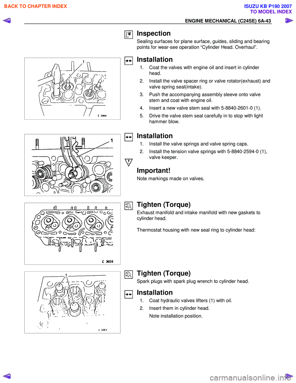
1. Coat the valves with engine oil and insert in cylinder head.
2. Install the valve spacer ring or valve rotator(exhaust) and valve spring seal(intake).
3. Push the accompanying assembly sleeve onto valve stem and coat with engine oil.
4. Insert a new valve stem seal with 5-8840-2601-0 (1).
5. Drive the valve stem seal carefully in to stop with light hammer blow.
Installation
1. Install the valve springs and valve spring caps.
2. Install the tension valve springs with 5-8840-2594-0 (1), valve keeper.
Important!
Note markings made on valves.
Tighten (Torque)
Exhaust manifold and intake manifold with new gaskets to
cylinder head.
Thermostat housing with new seal ring to cylinder head:
Tighten (Torque)
Spark plugs with spark plug wrench to cylinder head.
Installation
1. Coat hydraulic valves lifters (1) with oil.
2. Insert them in cylinder head.
Note installation position.
BACK TO CHAPTER INDEX
TO MODEL INDEX
ISUZU KB P190 2007
Page 2093 of 6020
ENGINE MECHANICAL (C24SE) 6A-79
Adjustment Values/Checking Values
Valve clearance Inlet Hydraulic valve lash adjustment
Outlet No adjustment necessary
Spark plugs - electrode gap 1.0 ∼ 1.1mm
Compression The difference in compression
between the individual cylinders
in the engine must not exceed
100 kPa (1 bar).
Pressure loss The pressure loss of an engine
in perfect condition per cylinder
is not more than max. 25%
Cylinder Head
Cylinder Head Gasket
Thickness - installed mm 1.2
Valve seat width at cylinder head
inlet mm 1.0 to 1.5
outlet mm 1.7 to 2.2
Valve stem play inlet mm 0.018 to 0.052
outlet mm 0.038 to 0.072
Permissible valve stem to cone runout
inlet mm 0.03
outlet mm 0.33
Overall height of cylinder head
(Sealing surface to sealing surface) mm 95.5 ± 0.25
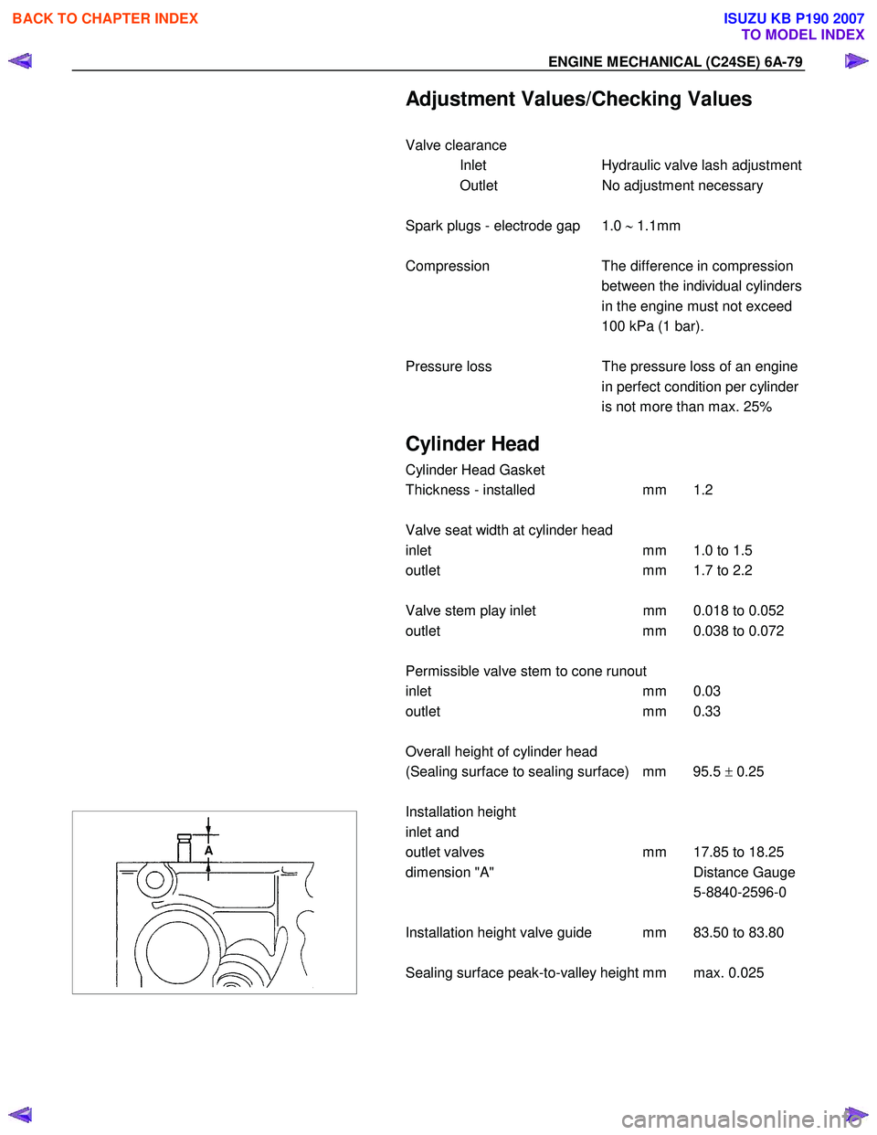
Installation height
inlet and
outlet valves mm 17.85 to 18.25
dimension "A" Distance Gauge
5-8840-2596-0
Installation height valve guide mm 83.50 to 83.80
Sealing surface peak-to-valley height mm max. 0.025
BACK TO CHAPTER INDEX
TO MODEL INDEX
ISUZU KB P190 2007
Page 2102 of 6020
6A-88 ENGINE MECHANICAL (C24SE)
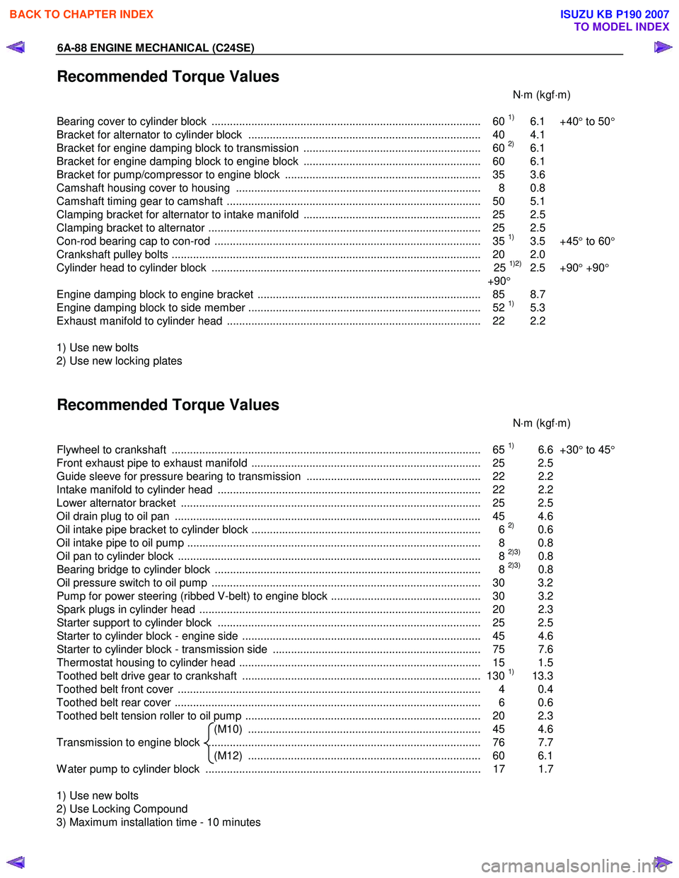
Recommended Torque Values
N⋅m (kgf ⋅m)
Bearing cover to cylinder block ........................................................................................ 60
1) 6.1 +40 ° to 50 °
Bracket for alternator to cylinder block ............................................................................ 40 4.1
Bracket for engine damping block to transmission .......................................................... 60
2) 6.1
Bracket for engine damping block to engine block .......................................................... 60 6.1
Bracket for pump/compressor to engine block ................................................................ 35 3.6
Camshaft housing cover to housing ................................................................................ 8 0.8
Camshaft timing gear to camshaft ................................................................................... 50 5.1
Clamping bracket for alternator to intake manifold .......................................................... 25 2.5
Clamping bracket to alternator ......................................................................................... 25 2.5
Con-rod bearing cap to con-rod ....................................................................................... 35
1) 3.5 +45 ° to 60 °
Crankshaft pulley bolts ..................................................................................................... 2 0 2.0
Cylinder head to cylinder block ........................................................................................ 25
1)2) 2.5 +90 ° +90 °
+90 °
Engine damping block to engine bracket ......................................................................... 85 8.7
Engine damping block to side member ............................................................................ 52
1) 5.3
Exhaust manifold to cylinder head ................................................................................... 22 2.2
1) Use new bolts
2) Use new locking plates
Recommended Torque Values
N⋅m (kgf ⋅m)
Flywheel to crankshaft ..................................................................................................... 65
1) 6.6 +30° to 45 °
Front exhaust pipe to exhaust manifold ........................................................................... 25 2.5
Guide sleeve for pressure bearing to transmission ......................................................... 22 2.2
Intake manifold to cylinder head ...................................................................................... 22 2.2
Lower alternator bracket .................................................................................................. 25 2.5
Oil drain plug to oil pan .................................................................................................... 45 4.6
Oil intake pipe bracket to cylinder block ........................................................................... 6
2) 0.6
Oil intake pipe to oil pump ................................................................................................ 8 0.8
Oil pan to cylinder block ................................................................................................... 8
2)3) 0.8
Bearing bridge to cylinder block ....................................................................................... 8 2)3) 0.8
Oil pressure switch to oil pump ........................................................................................ 30 3.2
Pump for power steering (ribbed V-belt) to engine block ................................................. 30 3.2
Spark plugs in cylinder head ............................................................................................ 20 2. 3
Starter support to cylinder block ...................................................................................... 25 2.5
Starter to cylinder block - engine side .............................................................................. 45 4.6
Starter to cylinder block - transmission side .................................................................... 75 7.6
Thermostat housing to cylinder head ............................................................................... 15 1.5
Toothed belt drive gear to crankshaft .............................................................................. 130
1) 13.3
Toothed belt front cover ................................................................................................... 4 0.4
Toothed belt rear cover .................................................................................................... 6 0.6
Toothed belt tension roller to oil pump ............................................................................. 20 2.3 (M10) ............................................................................ 45 4.6
Transmission to engine block ......................................................................................... 76 7.7 (M12) ............................................................................ 60 6.1
W ater pump to cylinder block .......................................................................................... 17 1.7
1) Use new bolts
2) Use Locking Compound
3) Maximum installation time - 10 minutes
BACK TO CHAPTER INDEX
TO MODEL INDEX
ISUZU KB P190 2007
Page 2146 of 6020
IGNITION SYSTEM 6D2-3
Spark Plug
Removal
1. Remove spark plugs.
Inspection and Repair
The spark plug affects entire engine performance and
therefore its inspection is very important.
• Check electrode and insulator for presence of cracks, and
replace if any.
• Check electrode for wear, and replace if necessary.
• Check gasket for damage, and replace if necessary.
• Measure insulation resistance with an ohmmeter, and
replace if faulty.
• Adjust spark plug gap to 1.0 - 1.1 mm (0.027 in) - 0.8 mm
(0.031 in).
• Check fuel and electrical systems if spark plug is extremely
dirty.
• Use spark plugs having low heat value (hot type plug) if fuel
and electrical systems are normal.
• Use spark plugs having high heat value (cold type plug) i
f
insulator and electrode are extremely burned.
Sooty Spark Plugs
Much deposit of carbon or oil on the electrode and insulator of
spark plug reduces the engine performance.
Possible causes:
• Too rich mixture
• Presence of oil in combustion chamber
• Incorrectly adjusted spark plug gap
Burning Electrodes
This fault is characterized by scorched or heavily oxidized
electrode or blistered insulator nose.
Possible causes:
• Too lean mixture
• Improper heat value
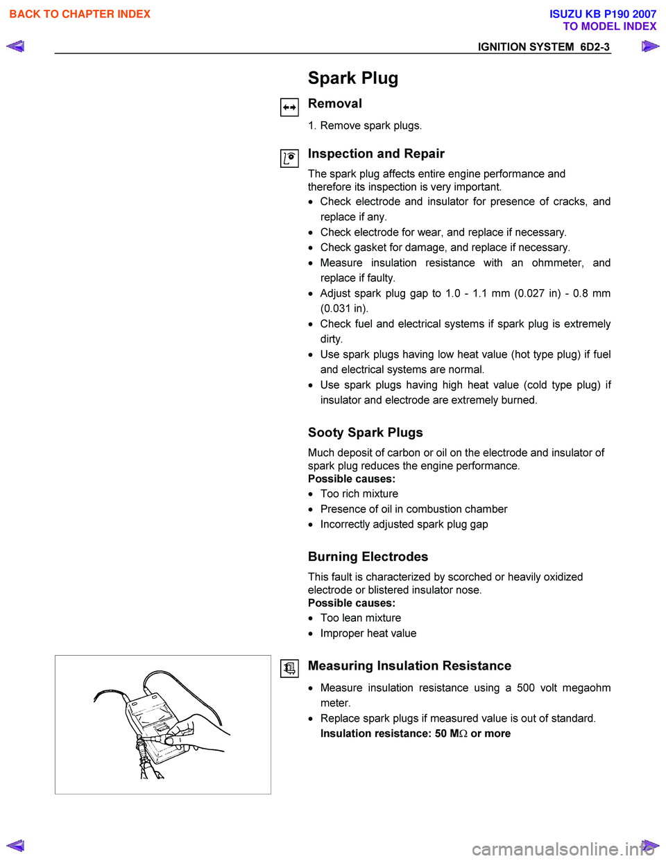
Measuring Insulation Resistance
• Measure insulation resistance using a 500 volt megaohm
meter.
• Replace spark plugs if measured value is out of standard.
Insulation resistance: 50 M Ω or more
BACK TO CHAPTER INDEX
TO MODEL INDEX
ISUZU KB P190 2007
Page 2147 of 6020
6D2-4 IGNITION SYSTEM
Cleaning Spark Plugs
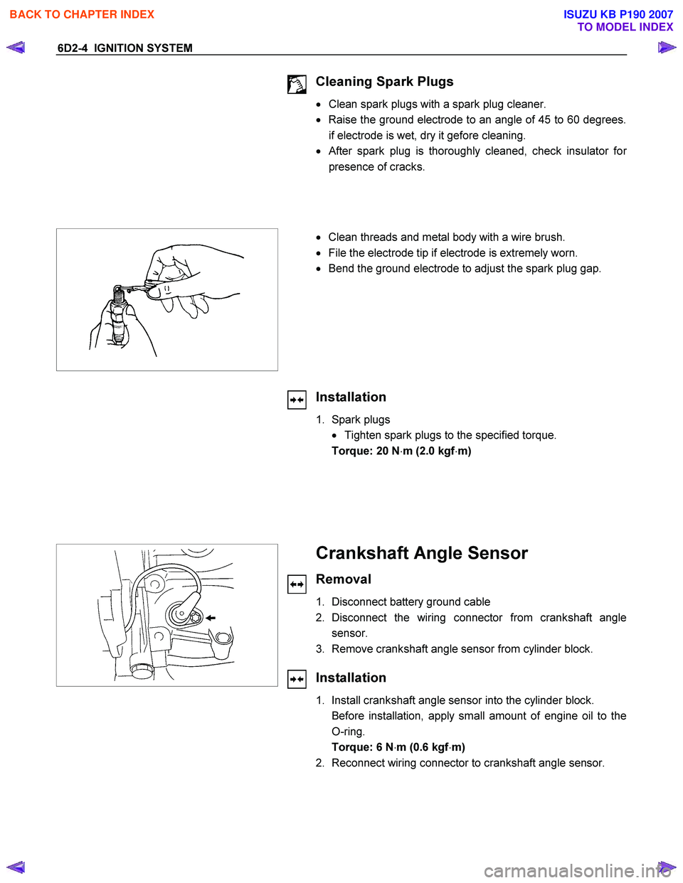
• Clean spark plugs with a spark plug cleaner.
• Raise the ground electrode to an angle of 45 to 60 degrees.
if electrode is wet, dry it gefore cleaning.
•
After spark plug is thoroughly cleaned, check insulator for
presence of cracks.
• Clean threads and metal body with a wire brush.
• File the electrode tip if electrode is extremely worn.
• Bend the ground electrode to adjust the spark plug gap.
Installation
1. Spark plugs
• Tighten spark plugs to the specified torque.
Torque: 20 N ⋅m (2.0 kgf ⋅m)
Crankshaft Angle Sensor
Removal
1. Disconnect battery ground cable
2. Disconnect the wiring connector from crankshaft angle sensor.
3. Remove crankshaft angle sensor from cylinder block.
Installation
1. Install crankshaft angle sensor into the cylinder block.
Before installation, apply small amount of engine oil to the O-ring.
Torque: 6 N ⋅m (0.6 kgf ⋅m)
2. Reconnect wiring connector to crankshaft angle sensor.
BACK TO CHAPTER INDEX
TO MODEL INDEX
ISUZU KB P190 2007
Page 2175 of 6020
ENGINE DRIVEABILITY AND EMISSIONS 6E–5
ENGINE CRANKS BUT WILL NOT RUN ..... 6E-233
HARD START SYMPTOM ............................ 6E-236
ROUGH, UNSTABLE, OR INCORRECT IDLE, STALLING SYMPTOM ............................... 6E-239
SURGES AND/OR CHUGS SYMPTOM ...... 6E-242
HESITATION, SAG, STUMBLE SYMPTOM 6E-245
CUTS OUT, MISSES SYMPTOM ................. 6E-248
LACK OF POWER, SLUGGISH OR SPONGY SYMPTOM ................................................. 6E-251
DETONATION/SPARK KNOCK SYMPTOM 6E-254
POOR FUEL ECONOMY SYMPTOM .......... 6E-256
EXCESSIVE EXHAUST EMISSIONS OR ODORS SYMPTOM ................................... 6E-258
DIESELING, RUN-ON SYMPTOM ............... 6E-261
BACKFIRE SYMPTOM ................................. 6E-262
ON-VEHICLE SERVICE PROCEDURE ....... 6E-264
ENGINE CONTROL MODULE (ECM) .......... 6E-264
CRANKSHAFT POSITION (CKP) SENSOR 6E-264
ENGINE COOLANT TEMPERATURE (ECT) SENSOR .................................................... 6E-265
INTAKE AIR TEMPERATURE (IAT) SENSOR 6E-265
MANIFOLD ABSOLUTE PRESSURE (MAP) SENSOR .................................................... 6E-266
THROTTLE POSITION SENSOR (TPS) ...... 6E-266
IDLE AIR CONTROL (IAC) VALVE .............. 6E-267
KNOCK SENSOR ......................................... 6E-268
POWER STEERING PRESSURE (PSP) SWITCH ..................................................... 6E-268
HEATED OXYGEN SENSOR (HO2S) ......... 6E-269
EVAP CANISTER PURGE VALVE SOLENOID 6E-269
FUEL PRESSURE RELIEF .......................... 6E-270
FUEL RAIL ASSEMBLY ............................... 6E-270
FUEL INJECTOR .......................................... 6E-271
FUEL PRESSURE REGULATOR ................ 6E-273
IGNITION COIL ............................................ 6E-275
SPARK PLUGS ............................................ 6E-275
SPARK PLUG CABLES ................................ 6E-277
EMISSION CONTROL ; *CO ADJUSTER (W/O
CATALYSTIC CONVERTER) .................. 6E-277
SPECIAL SERVICE TOOLS ......................... 6E-279
BACK TO CHAPTER INDEX
TO MODEL INDEX
ISUZU KB P190 2007
Page 2224 of 6020
6E–54 ENGINE DRIVEABILITY AND EMISSIONS
GENERAL DESCRIPTION FOR ELECTRIC
IGNITION SYSTEM
The engine use two ignition coils, one per two cylinders.
A two wire connector provides a battery voltage primary
supply through the ignition fuse.
The ignition control spark timing is the ECM’s method of
controlling the spark advance and the ignition dwell.
The ignition control spark advance and the ignition dwell
are calculated by the ECM using the following inputs.
• Engine speed
• Crankshaft position (CKP) sensor
• Engine coolant temperature (ECT) sensor
• Throttle position sensor
• Vehicle speed sensor
• ECM and ignition system supply voltage
Ignition coil works to generate only the secondary
voltage be receiving the primary voltage from ECM.
The primary voltage is generated at the coil driver
located in the ECM. The coil driver generate the primary
voltage based on the crankshaft position signal. In
accordance with the crankshaft position signal, ignition
coil driver determines the adequate ignition timing and
also cylinder number to ignite.
Ignition timing is determined the coolant temperature,
intake air temperature, engine speed, engine load,
knock sensor signal, etc.
Spark Plug
Although worn or dirty spark plugs may give satisfactory
operation at idling speed, they frequently fail at higher
engine speeds. Faulty spark plugs may cause poor fuel
economy, power loss, loss of speed, hard starting and
generally poor engine performance. Follow the
scheduled maintenance service recommendations to
ensure satisfactory spark plug performance. Refer to
Maintenance and Lubrication .
Normal spark plug operation will result in brown to
grayish-tan deposits appearing on the insulator portion
of the spark plug. A small amount of red-brown, yellow,
and white powdery material may also be present on the
insulator tip around the center electrode. These
deposits are normal combustion by-products of fuels
and lubricating oils with additives. Some electrode wear
will also occur. Engines which are not running properly
are often referred to as “misfiring.” This means the
ignition spark is not igniting the air/fuel mixture at the
proper time. While other ignition and fuel system causes
must also be considered, possible causes include
ignition system conditions which allow the spark voltage
to reach ground in some other manner than by jumping
across the air gap at the tip of the spark plug, leaving
the air/fuel mixture unburned. Misfiring may also occur
when the tip of the spark plug becomes overheated and
ignites the mixture before the spark jumps. This is
referred to as “pre-ignition.”
Spark plugs may also misfire due to fouling, excessive
gap, or a cracked or broken insulator. If misfiring occurs before the recommended replacement interval, locate
and correct the cause.
Carbon fouling of the spark plug is indicated by dry,
black carbon (soot) deposits on the portion of the spark
plug in the cylinder. Excessive idling and slow speeds
under light engine loads can keep the spark plug
temperatures so low that these deposits are not burned
off. Very rich fuel mixtures or poor ignition system output
may also be the cause. Refer to DTC P1167.
Oil fouling of the spark plug is indicated by wet oily
deposits on the portion of the spark plug in the cylinder,
usually with little electrode wear. This may be caused by
oil during break-in of new or newly overhauled engines.
Deposit fouling of the spark plug occurs when the
normal red-brown, yellow or white deposits of
combustion by-products become sufficient to cause
misfiring. In some cases, these deposits may melt and
form a shiny glaze on the insulator around the center
electrode. If the fouling is found in only one or two
cylinders, valve stem clearances or intake valve seals
may be allowing excess lubricating oil to enter the
cylinder, particularly if the deposits are heavier on the
side of the spark plug facing the intake valve.
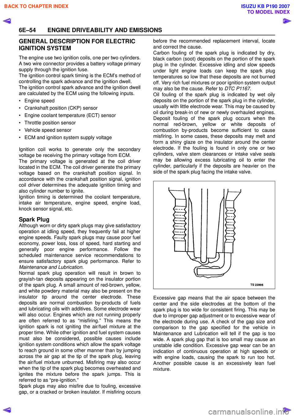
Excessive gap means that the air space between the
center and the side electrodes at the bottom of the
spark plug is too wide for consistent firing. This may be
due to improper gap adjustment or to excessive wear of
the electrode during use. A check of the gap size and
comparison to the gap specified for the vehicle in
Maintenance and Lubrication will tell if the gap is too
wide. A spark plug gap that is too small may cause an
unstable idle condition. Excessive gap wear can be an
indication of continuous operation at high speeds or
with engine loads, causing the spark to run too hot.
Another possible cause is an excessively lean fuel
mixture.
BACK TO CHAPTER INDEX
TO MODEL INDEX
ISUZU KB P190 2007
Page 2225 of 6020
ENGINE DRIVEABILITY AND EMISSIONS 6E–55
Low or high spark plug installation torque or improper
seating can result in the spark plug running too hot and
can cause excessive center electrode wear. The plug
and the cylinder head seats must be in good contact for
proper heat transfer and spark plug cooling. Dirty or
damaged threads in the head or on the spark plug can
keep it from seating even though the proper torque is
applied. Once spark plugs are properly seated, tighten
them to the torque shown in the Specifications Table.
Low torque may result in poor contact of the seats due
to a loose spark plug. Over tightening may cause the
spark plug shell to be stretched and will result in poor
contact between the seats. In extreme cases, exhaust
blow-by and damage beyond simple gap wear may
occur.
Cracked or broken insulators may be the result of
improper installation, damage during spark plug re-
gapping, or heat shock to the insulator material. Upper
insulators can be broken when a poorly fitting tool is
used during installation or removal, when the spark plug
is hit from the outside, or is dropped on a hard surface.
Cracks in the upper insulator may be inside the shell
and not visible. Also, the breakage may not cause
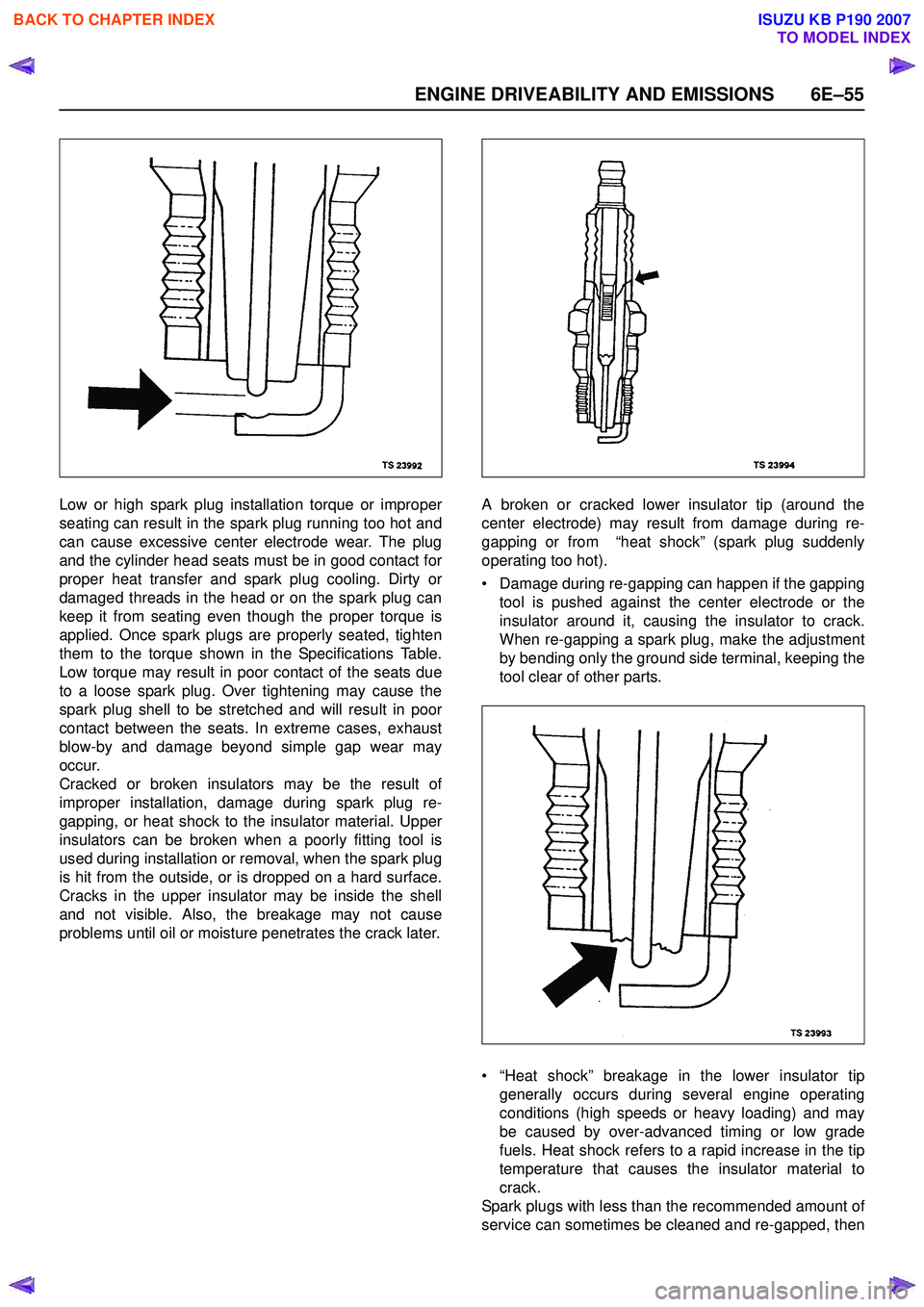
problems until oil or moisture penetrates the crack later. A broken or cracked lower insulator tip (around the
center electrode) may result from damage during re-
gapping or from “heat shock” (spark plug suddenly
operating too hot).
• Damage during re-gapping can happen if the gapping tool is pushed against the center electrode or the
insulator around it, causing the insulator to crack.
When re-gapping a spark plug, make the adjustment
by bending only the ground side terminal, keeping the
tool clear of other parts.
• “Heat shock” breakage in the lower insulator tip generally occurs during several engine operating
conditions (high speeds or heavy loading) and may
be caused by over-advanced timing or low grade
fuels. Heat shock refers to a rapid increase in the tip
temperature that causes the insulator material to
crack.
Spark plugs with less than the recommended amount of
service can sometimes be cleaned and re-gapped, then
BACK TO CHAPTER INDEX
TO MODEL INDEX
ISUZU KB P190 2007