2007 ISUZU KB P190 seats
[x] Cancel search: seatsPage 2652 of 6020
Engine Mechanical – V6 Page 6A1–173
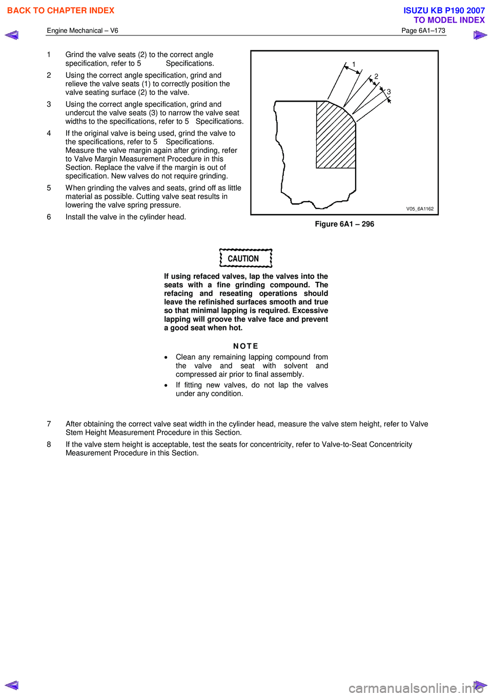
1 Grind the valve seats (2) to the correct angle
specification, refer to 5 Specifications.
2 Using the correct angle specification, grind and relieve the valve seats (1) to correctly position the
valve seating surface (2) to the valve.
3 Using the correct angle specification, grind and undercut the valve seats (3) to narrow the valve seat
widths to the specifications, refer to 5 Specifications.
4 If the original valve is being used, grind the valve to the specifications, refer to 5 Specifications.
Measure the valve margin again after grinding, refer
to Valve Margin Measurement Procedure in this
Section. Replace the valve if the margin is out of
specification. New valves do not require grinding.
5 W hen grinding the valves and seats, grind off as little material as possible. Cutting valve seat results in
lowering the valve spring pressure.
6 Install the valve in the cylinder head.
Figure 6A1 – 296
CAUTION
If using refaced valves, lap the valves into the
seats with a fine grinding compound. The
refacing and reseating operations should
leave the refinished surfaces smooth and true
so that minimal lapping is required. Excessive
lapping will groove the valve face and prevent
a good seat when hot.
NOTE
• Clean any remaining lapping compound from
the valve and seat with solvent and
compressed air prior to final assembly.
• If fitting new valves, do not lap the valves
under any condition.
7 After obtaining the correct valve seat width in the cylinder head, measure the valve stem height, refer to Valve Stem Height Measurement Procedure in this Section.
8 If the valve stem height is acceptable, test the seats for concentricity, refer to Valve-to-Seat Concentricity Measurement Procedure in this Section.
BACK TO CHAPTER INDEX
TO MODEL INDEX
ISUZU KB P190 2007
Page 2785 of 6020
Engine Mechanical – V6 Page 6A1–8
Page 6A1–8
1 General Information
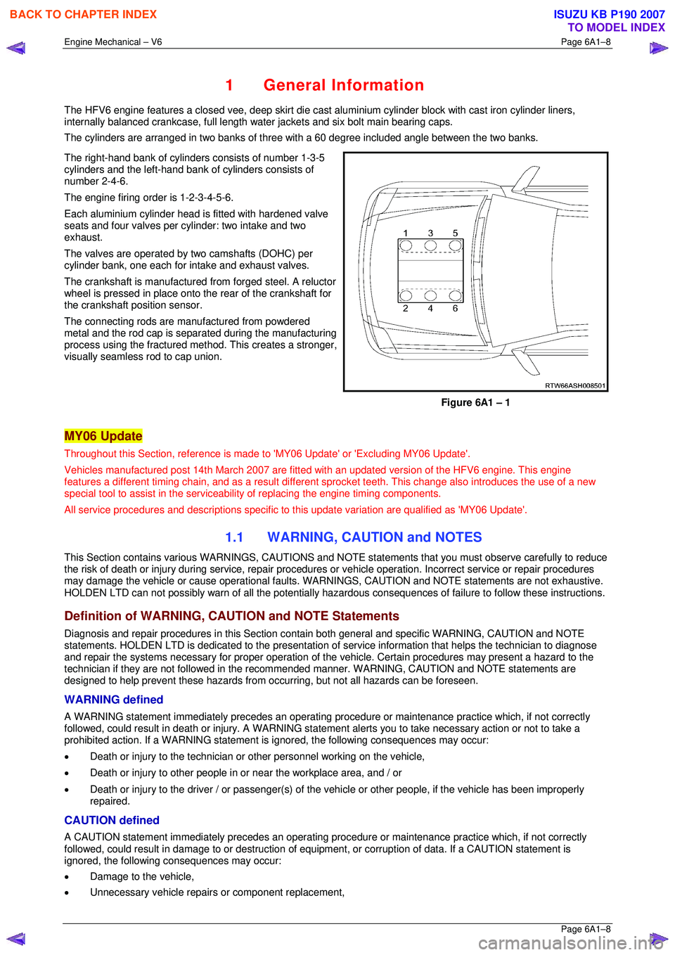
The HFV6 engine features a closed vee, deep skirt die cast aluminium cylinder block with cast iron cylinder liners,
internally balanced crankcase, full length wa ter jackets and six bolt main bearing caps.
The cylinders are arranged in two banks of three with a 60 degree included angle between the two banks.
The right-hand bank of cylinders consists of number 1-3-5
cylinders and the left-hand bank of cylinders consists of
number 2-4-6.
The engine firing order is 1-2-3-4-5-6.
Each aluminium cylinder head is fitted with hardened valve
seats and four valves per cylinder: two intake and two
exhaust.
The valves are operated by two camshafts (DOHC) per
cylinder bank, one each for intake and exhaust valves.
The crankshaft is manufactured from forged steel. A reluctor
wheel is pressed in place onto the rear of the crankshaft for
the crankshaft position sensor.
The connecting rods are m anufactured from powdered
metal and the rod cap is separ ated during the manufacturing
process using the fractured me thod. This creates a stronger,
visually seamless rod to cap union.
Figure 6A1 – 1
MY06 Update
Throughout this Section, reference is made to 'MY06 Update' or 'Excluding MY06 Update'.
Vehicles manufactured post 14th Marc h 2007 are fitted with an updated version of the HFV6 engine. This engine
features a different timing chain, and as a result different sprocket teeth. This change also introduces the use of a new
special tool to assist in the serviceab ility of replacing the engine timing components.
All service procedures and descriptions specific to this update variation are qualified as 'MY06 Update'.
1.1 WARNING, CAUTION and NOTES
This Section contains various WARNING S, CAUTIONS and NOTE statements that y ou must observe carefully to reduce
the risk of death or injury during servic e, repair procedures or vehicle operation. Incorrect service or repair procedures
may damage the vehicle or cause operat ional faults. WARNINGS, CAUTION and NOTE statements are not exhaustive.
HOLDEN LTD can not possibly warn of a ll the potentially hazardous consequences of failure to follow these instructions.
Definition of WARNING, CAUTION and NOTE Statements
Diagnosis and repair procedures in this Section contain both general and specific WARNING, CAUTION and NOTE
statements. HOLDEN LTD is dedicated to the presentation of service information that helps the technician to diagnose
and repair the systems necessary for proper operation of the vehicle. Certain procedures may present a hazard to the
technician if they are not followed in the reco mmended manner. WARNING, CAUTION and NOTE statements are
designed to help prevent these hazards from o ccurring, but not all hazards can be foreseen.
WARNING defined
A WARNING statement immediately precedes an operating procedure or maint enance practice which, if not correctly
followed, could result in death or injury . A WARNING statement alerts you to ta ke necessary action or not to take a
prohibited action. If a WARNING statement is ignored, the following consequences may occur:
• Death or injury to the technician or other personnel working on the vehicle,
• Death or injury to other people in or near the workplace area, and / or
• Death or injury to the driver / or passenger(s) of the vehicle or other people, if the vehicle has been improperly
repaired.
CAUTION defined
A CAUTION statement immediately prec edes an operating procedure or maintenance practice which, if not correctly
followed, could result in damage to or destruction of equi pment, or corruption of data. If a CAUTION statement is
ignored, the following consequences may occur:
• Damage to the vehicle,
• Unnecessary vehicle repairs or component replacement,
BACK TO CHAPTER INDEX
TO MODEL INDEX
ISUZU KB P190 2007
Page 2991 of 6020
Engine Mechanical – V6 Page 6A1–214
Page 6A1–214
Reinstall
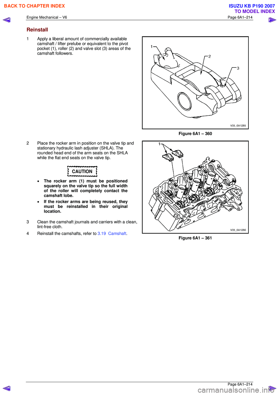
1 Apply a liberal amount of commercially available
camshaft / lifter prelube or equivalent to the pivot
pocket (1), roller (2) and valve slot (3) areas of the
camshaft followers.
Figure 6A1 – 360
2 Place the rocker arm in position on the valve tip and stationary hydraulic lash adjuster (SHLA). The
rounded head end of the arm seats on the SHLA
while the flat end seats on the valve tip.
CAUTION
• The rocker arm (1) must be positioned
squarely on the valve tip so the full width
of the roller will completely contact the
camshaft lobe.
• If the rocker arms are being reused, they
must be reinstalled in their original
location.
3 Clean the camshaft journals and carriers with a clean, lint-free cloth.
4 Reinstall the camshafts, refer to 3.19 Camshaft.
Figure 6A1 – 361
BACK TO CHAPTER INDEX
TO MODEL INDEX
ISUZU KB P190 2007
Page 3005 of 6020
Engine Mechanical – V6 Page 6A1–228
Page 6A1–228
Valve-to-Seat Concentricity Measurement Procedure
Checking the valve-to-seat concentricity determines whether the valve and seat are sealing correctly.
Measure the valve face and the valve s eat to ensure correct valve sealing.
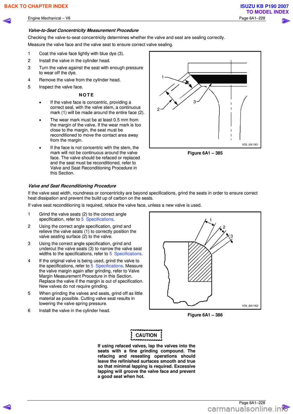
1 Coat the valve face lightly with blue dye (3).
2 Install the valve in the cylinder head.
3 Turn the valve against the seat with enough pressure to wear off the dye.
4 Remove the valve from the cylinder head.
5 Inspect the valve face.
NOTE
• If the valve face is concentric, providing a
correct seal, with the valve stem, a continuous
mark (1) will be made around the entire face (2).
• The wear mark must be at least 0.5 mm from
the margin of the valve. If the wear mark is too
close to the margin, the seat must be
reconditioned to move the contact area away
from the margin.
• If the face is not concentric with the stem, the
mark will not be continuous around the valve
face. The valve should be refaced or replaced
and the seat must be reconditioned, refer to
Valve and Seat Reconditioning Procedure in
this Section.
Figure 6A1 – 385
Valve and Seat Reconditioning Procedure
If the valve seat width, roundness or conc entricity are beyond specifications, grind the seats in order to ensure correct
heat dissipation and prevent the bu ild up of carbon on the seats.
If valve seat reconditioning is required, reface the valve face, unless a new valve is used.
1 Grind the valve seats (2) to the correct angle specification, refer to 5 Specifications.
2 Using the correct angle specification, grind and
relieve the valve seats (1) to correctly position the
valve seating surface (2) to the valve.
3 Using the correct angle specification, grind and
undercut the valve seats (3) to narrow the valve seat
widths to the specifications, refer to 5 Specifications.
4 If the original valve is being used, grind the valve to the specifications, refer to 5 Specifications. Measure
the valve margin again after grinding, refer to Valve
Margin Measurement Procedure in this Section.
Replace the valve if the margin is out of specification.
New valves do not require grinding.
5 When grinding the valves and seats, grind off as little material as possible. Cutti ng valve seat results in
lowering the valve spring pressure.
6 Install the valve in the cylinder head.
Figure 6A1 – 386
CAUTION
If using refaced valves, lap the valves into the
seats with a fine grinding compound. The
refacing and reseati ng operations should
leave the refinished surfaces smooth and true
so that minimal lapping is required. Excessive
lapping will groove the valve face and prevent
a good seat when hot.
BACK TO CHAPTER INDEX
TO MODEL INDEX
ISUZU KB P190 2007
Page 3006 of 6020
Engine Mechanical – V6 Page 6A1–229
Page 6A1–229
NOTE
• Clean any remaining lapping compound from
the valve and seat with solvent and
compressed air prior to final assembly.
• If fitting new valves, do not lap the valves
under any condition.
7 After obtaining the correct valve seat width in the cylinder head, measure the valve stem height, refer to Valve
Stem Height Measurement Pr ocedure in this Section.
8 If the valve stem height is acceptabl e, test the seats for concentricity, refer to Valve-to-Seat Concentricity
Measurement Procedure in this Section.
Valve Stem Height Measurement Procedure
CAUTION
To determine the valve stem height
measurement, measure from the valve
spring seat to the valve spring retainer.
1 Install the valve into the valve guide.
2 Ensure the valve is seated to the valve seat.
3 Install the valve stem oil seal.
4 Install the valve spring retainer and valve stem keys.
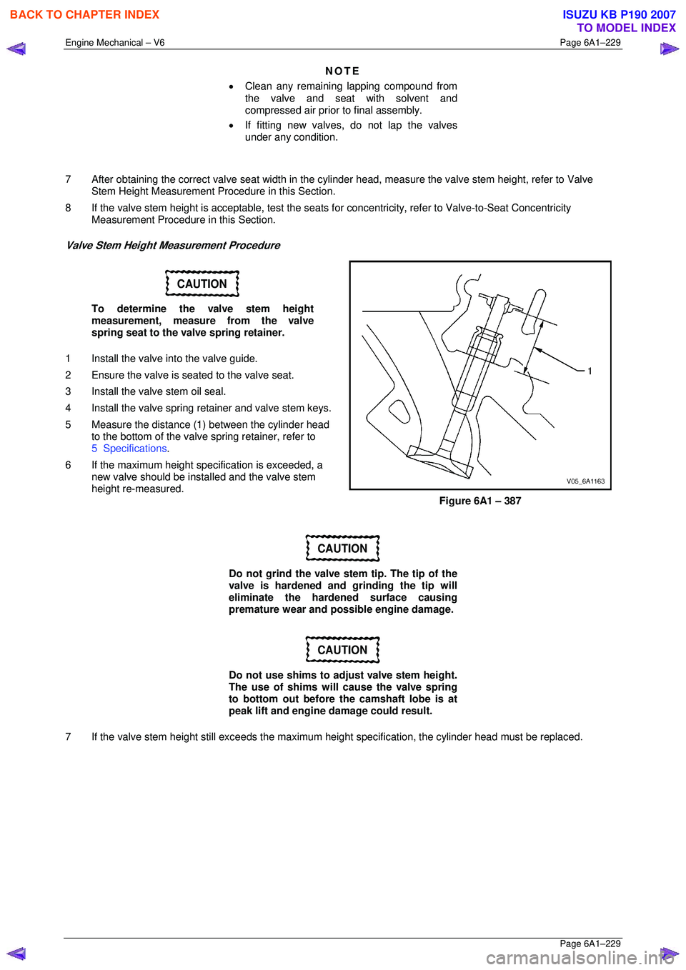
5 Measure the distance (1 ) between the cylinder head
to the bottom of the valve spring retainer, refer to
5 Specifications .
6 If the maximum height spec ification is exceeded, a
new valve should be installed and the valve stem
height re-measured.
Figure 6A1 – 387
CAUTION
Do not grind the valve stem tip. The tip of the
valve is hardened and grinding the tip will
eliminate the hardened surface causing
premature wear and possible engine damage.
CAUTION
Do not use shims to adjust valve stem height.
The use of shims will cause the valve spring
to bottom out before the camshaft lobe is at
peak lift and engine damage could result.
7 If the valve stem height still exceeds the maximum height specification, the cylinder head must be replaced.
BACK TO CHAPTER INDEX
TO MODEL INDEX
ISUZU KB P190 2007
Page 3933 of 6020
Automatic Transmission – 4L60E – On-vehicle Servicing Page 7C4–20
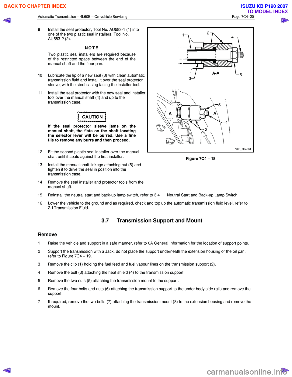
9 Install the seal protector, Tool No. AU583-1 (1) into
one of the two plastic seal installers, Tool No.
AU583-2 (2).
NOTE
Two plastic seal installers are required because
of the restricted space between the end of the
manual shaft and the floor pan.
10 Lubricate the lip of a new seal (3) with clean automatic transmission fluid and install it over the seal protector
sleeve, with the steel casing facing the installer tool.
11 Install the seal protector with the new seal and installer tool over the manual shaft (4) and up to the
transmission case.
If the seal protector sleeve jams on the
manual shaft, the flats on the shaft locating
the selector lever will be burred. Use a fine
file to remove any burrs and then proceed.
12 Fit the second plastic seal installer over the manual shaft until it seats against the first installer.
13 Install the manual shaft linkage attaching nut (5) and tighten it to drive the seal in position into the
transmission case.
14 Remove the seal installer and protector tools from the manual shaft.
Figure 7C4 – 18
15 Reinstall the neutral start and back-up lamp switch, refer to 3.4 Neutral Start and Back-up Lamp Switch.
16 Lower the vehicle to the ground and as required, check and top up the automatic transmission fluid level, refer to 2.1 Transmission Fluid.
3.7 Transmission Support and Mount
Remove
1 Raise the vehicle and support in a safe manner, refer to 0A General Information for the location of support points.
2 Support the transmission with a Jack, do not place the support underneath the extension housing or the oil pan, refer to Figure 7C4 – 19.
3 Remove the clip (1) holding the fuel feed and fuel vapour lines on the transmission support (2).
4 Remove the bolt (3) attaching the heat shield (4) to the transmission support.
5 Remove the two nuts (5) attaching the transmission mount to the support.
6 Remove the four bolts and nuts (6) attaching the transmission support to the under body side rails and remove the support.
7 If required, remove the two bolts (7) attaching the transmission mount (8) to the extension housing and remove the mount.
BACK TO CHAPTER INDEX
TO MODEL INDEX
ISUZU KB P190 2007
Page 5663 of 6020
9A-28 SUPPLEMENTAL RESTRAINT SYSTEM
20. The passenger inflator requires no special
precaution after deployment. 95% of the
particulate emission is potassium chloride (KLC),
which is commonly sold as an edible salt-
substitute. Even if water is applied, post
deployment products are relatively pH neutral.
Disposing of the inflator by burying it in a landfill
will not produce any hazardous products. As with
any dusty environment, safety goggles, dust mask
and gloves should be worn.
WARNING: SAFETY PRECAUTIONS MUST BE
OBSERVED WHEN HANDLING A DEPLOYED AIR
BAG ASSEMBLY. AFTER DEPLOYMENT, THE
METAL SURFACES OF THE AIR BAG ASSEMBLY
WILL BE HOT. ALLOW THE AIR BAG ASSEMBLY
TO COOL BEFORE HANDLING ANY METAL
PORTION OF IT. DO NOT PLACE THE DEPLOYED
INFLATOR MODULE NEAR ANY FLAMMABLE
OBJECTS. FAILURE TO FOLLOW PROCEDURES
MAY RESULT IN FIRE OR PERSONAL INJURY.
AFTER AN AIR BAG ASSEMBLY HAS BEEN
DEPLOYED, THE METAL CANISTER AND
SURROUNDING AREAS OF THE AIR BAG
ASSEMBLY WILL BE HOT. DO NOT TOUCH THE
METAL AREAS OF THE AIR BAG ASSEMBLY FOR
ABOUT THIRTY MINUTES AFTER DEPLOYMENT.
IF THE DEPLOYED AIR BAG ASSEMBLY MUST BE
MOVED BEFORE IT IS COOL, WEAR GLOVES AND
HANDLE BY THE AIR BAG ITSELF.
21. Disconnect the pigtail adapter from the air bag assembly as soon after deployment as possible to
avoid damage to the pigtail adapter or SRS
deployment harness from contacting the hot ai
r
bag assembly canister. The pigtail adapter and
SRS deployment harness are designed to be
reused. They should, however, be inspected fo
r
damage after each deployment and replaced if
necessary.
22. Dispose of the deployed air bag assembly through normal refuse channels after it has cooled for at
least 30 minutes.
23. W ash your hands with mild soap and wate
r
afterward.
NOTE: The remaining steps are to be followed in the
unlikely event that the air bag assembly did not deplo
y
after following the above procedures.
24. Ensure that the SRS deployment harness has been disconnected from the power source and that
its two banana plugs have been shorted togethe
r
by fully seating one banana plug into the other.
25. Disconnect the pigtail adapter from the air bag assembly.
WARNING: WHEN STORING A LIVE AIR BAG
ASSEMBLY OR WHEN LEAVING A LIVE AIR BAG
ASSEMBLY UNATTENDED ON A BENCH OR
OTHER SURFACE, ALWAYS FACE THE BAG UP
AND AWAY FROM THE SURFACE. THIS IS
NECESSARY SO THAT A FREE SPACE IS
PROVIDED TO ALLOW THE AIR BAG TO EXPAND
IN THE UNLIKELY EVENT OF
ACCIDENTAL
DEPLOYMENT. FAILURE TO FOLLOW
PROCEDURES MAY RESULT IN PERSONAL
INJURY.
26. Temporarily store the air bag assembly with the bag facing up, away from the surface upon which it
rests.
Deployment Inside Vehicle (Vehicle
Scrapping Procedure)
Deployment inside the vehicle is proper when the
vehicle is to be destroyed or salvaged for component
parts. This includes, but is not limited to, the following
situations:
1. The vehicle has completed its useful life.
2. The vehicle has been damaged beyond repair in a nondeployment type accident.
3. The vehicle has been stripped or damaged beyond repair in a theft.
4. The vehicle will be salvaged for component parts to be used on a vehicle with a different Vehicle
Identification Number (VIN) as opposed to being
rebuilt with the same VIN. Never use SRS
components from another vehicle.
WARNING: FAILURE TO FOLLOW PROPER SRS
AIR BAG ASSEMBLY DISPOSAL PROCEDURES
CAN RESULT IN AIR BAG DEPLOYMENT WHICH
MAY CAUSE PERSONAL INJURY. UNDEPLOYED
AIR BAG ASSEMBLIES MUST NOT BE DISPOSED
OF THROUGH NORMAL REFUSE CHANNELS.
THE UNDEPLOYED AIR BAG ASSEMBLY
CONTAINS SUBSTANCES THAT CAN CAUSE
SEVERE ILLNESS OR PERSONAL INJURY IF THE
SEALED CONTAINER IS DAMAGED DURING
DISPOSAL. DISPOSAL IN ANY MANNER
INCONSISTENT WITH PROPER PROCEDURES
MAY BE A VIOLATION OF FEDERAL, STATE
AND/OR LOCAL LAWS.
1. Turn the ignition switch to “LOCK,” remove the ke
y
and put on the safety glasses.
2. Remove all loose objects from the front seats.
3. Disconnect the driver air bag assembly yello
w
connector located at the base of the steering
column.
4. Cut the driver air bag assembly yellow harness connector from the vehicle leaving at least 15 cm
(six inches) of wire at the connector.
BACK TO CHAPTER INDEX TO MODEL INDEXISUZU KB P190 2007