2007 ISUZU KB P190 remote start
[x] Cancel search: remote startPage 3524 of 6020

Engine Management – V6 – Diagnostics Page 6C1-2–246
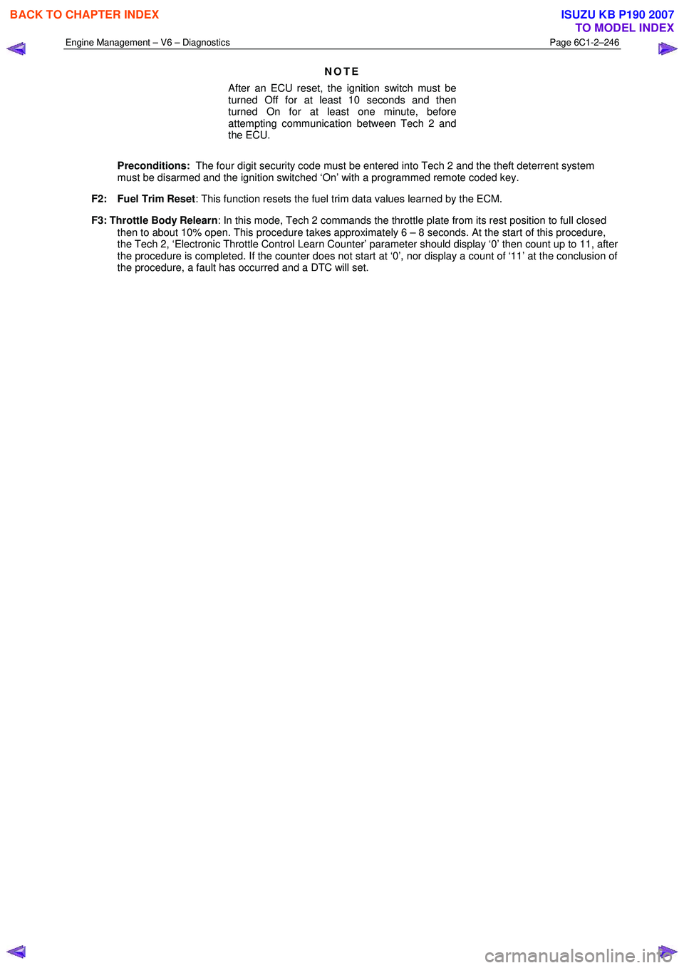
NOTE
After an ECU reset, the ignition switch must be
turned Off for at least 10 seconds and then
turned On for at least one minute, before
attempting communication between Tech 2 and
the ECU.
Preconditions: The four digit security code must be entered into Tech 2 and the theft deterrent system
must be disarmed and the ignition switched ‘On’ with a programmed remote coded key.
F2: Fuel Trim Reset : This function resets the fuel trim data values learned by the ECM.
F3: Throttle Body Relearn : In this mode, Tech 2 commands the throttle plate from its rest position to full closed
then to about 10% open. This procedure takes approximately 6 – 8 seconds. At the start of this procedure,
the Tech 2, ‘Electronic Throttle Control Learn Counter’ parameter should display ‘0’ then count up to 11, after
the procedure is completed. If the counter does not start at ‘0’, nor display a count of ‘11’ at the conclusion of
the procedure, a fault has occurred and a DTC will set.
BACK TO CHAPTER INDEX
TO MODEL INDEX
ISUZU KB P190 2007
Page 4285 of 6020

TRANSMISSION CONTROL SYSTEM (JR405E) 7A2-1
TRANSMISSION
TRANSMISSION CONTROL SYSTEM (JR405E)
This manual conforms when Scan Tool of ISO CAN Base Software is used.
TABLE OF CONTENTS
Specifications ...................................................... 7A2-2Transmission General Specifications ............... 7A2-2
Transmission Fluid Temperature vs. Resistance..... 7A2-3
Clutch, Brake, Solenoid and Pressure Switch Logic........ 7A2-4
Diagnostic Trouble Code (DTC) List ................ 7A2-5
Schematic and Routing Diagrams....................... 7A2-6 Transmission Controls Schematics .................. 7A2-6
Component Locator........................................... 7A2-13 Transmission Controls Component Views ..... 7A2-13
Transmission Control Module (TCM) Connector End Views ................................... 7A2-17
Transmission Control Connector End Views.. 7A2-18
Diagnostic Information and Procedures ............ 7A2-21
Diagnostic Starting Point - Transmission Controls......... 7A2-21
Diagnostic System Check - Transmission Controls....... 7A2-22
Scan Tool Data List ........................................ 7A2-24
Scan Tool Data Definitions............................. 7A2-25
Scan Tool Output Controls ............................. 7A2-27
Scan Tool Does Not Power Up ...................... 7A2-28
Scan Tool Does Not Communicate with Keyword Device .................................... 7A2-29
Lost Communication with The Transmission Control Module (TCM)
.... 7A2-31
DTC P0560 (Flash Code 16).......................... 7A2-33
DTC P0602 .................................................... 7A2-35
DTC P0705 (Flash Code 17).......................... 7A2-36
DTC P0710 (Flash Code 15).......................... 7A2-40
DTC P0717 (Flash Code 14).......................... 7A2-44
DTC P0722 (Flash Code 11).......................... 7A2-47
DTC P0727 (Flash Code 13).......................... 7A2-50
DTC P0731, P0732, P0733 or P0734 (Flash Code 41, 42, 43 or 44)....................... 7A2-52
DTC P0748 (Flash Code 35).......................... 7A2-55
DTC P0753 (Flash Code 31).......................... 7A2-58
DTC P0758 (Flash Code 32).......................... 7A2-61
DTC P0763 (Flash Code 33).......................... 7A2-64
DTC P0768 (Flash Code 34).......................... 7A2-67
DTC P1120 (Flash Code 22).......................... 7A2-70
DTC P1750 (Flash Code 51).......................... 7A2-71
DTC P1755 (Flash Code 52).......................... 7A2-73
DTC P1853 (Flash Code 26).......................... 7A2-75
DTC P1858 (Flash Code 27).......................... 7A2-78
DTC P1860 (Flash Code 36).......................... 7A2-81
DTC P1863 (Flash Code 28).......................... 7A2-84
DTC P1875 (Flash Code 25).......................... 7A2-87
Check Trans Lamp Inoperative, Always On or Always Blinking ...................... 7A2-89
Symptoms - Transmission Controls .................. 7A2-92 Symptoms - Transmission Controls ............... 7A2-92
Intermittent Conditions ................................... 7A2-93 Vehicle Does Not Run .................................... 7A2-95
Trouble at Starting.......................................... 7A2-95
Faulty Gearshift .............................................. 7A2-95
Faulty Shift Pattern......................................... 7A2-95
No or Error Gearshift ...................................... 7A2-95
Faulty Operation During Running................... 7A2-95
Faulty Operation in Stopping.......................... 7A2-95
Faulty Lock Up ............................................... 7A2-95
No Lock Up .................................................... 7A2-95
Transmission Fluid Leak ................................ 7A2-95
Others ............................................................ 7A2-95
Test Instructions .............................................. 7A2-121 Line Pressure Test ....................................... 7A2-121
Stall Test ...................................................... 7A2-123
Time Lag Test .............................................. 7A2-124
Road Test..................................................... 7A2-125
TCM Signal Test .......................................... 7A2-134
Repair Instructions .......................................... 7A2-139
Transmission Controls Module (TCM) Replacement.... 7A2-139
Service Programming System (SPS) Description........ 7A2-139
Service Programming System (SPS) (Remote Procedure)......................... 7A2-140
Service Programming System (SPS) (Pass-Thru Procedure)..................... 7A2-141
Description and Operation .............................. 7A2-143 Transmission Identification Information........ 7A2-143
Transmission General Description ............... 7A2-143
Transmission Component Description ......... 7A2-144
Transmission Control System Description ... 7A2-152
Transmission Power Flow Description ......... 7A2-161
Special Tools and Equipment ......................... 7A2-170 Special Tools and Equipment ...................... 7A2-170
BACK TO CHAPTER INDEX
TO MODEL INDEX
ISUZU KB P190 2007
Page 4378 of 6020

7A2-94 TRANSMISSION CONTROL SYSTEM (JR405E)
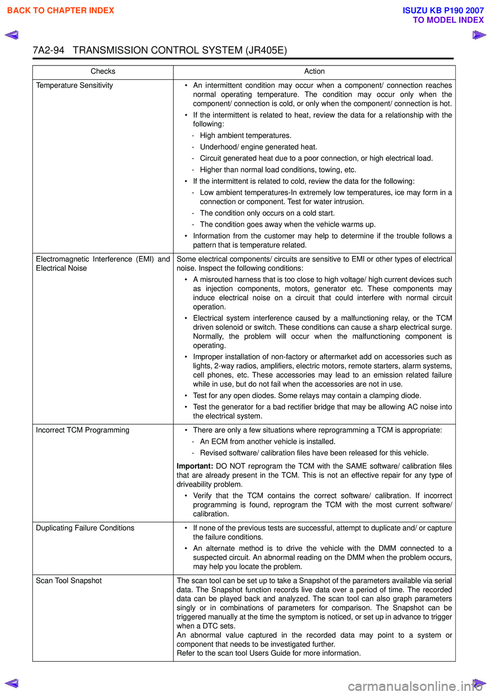
Temperature Sensitivity• An intermittent condition may occur when a component/ connection reaches
normal operating temperature. The condition may occur only when the
component/ connection is cold, or only when the component/ connection is hot.
• If the intermittent is related to heat, review the data for a relationship with the following:
- High ambient temperatures.
- Underhood/ engine generated heat.
- Circuit generated heat due to a poor connection, or high electrical load.
- Higher than normal load conditions, towing, etc.
• If the intermittent is related to cold, review the data for the following: - Low ambient temperatures-In extremely low temperatures, ice may form in a connection or component. Test for water intrusion.
- The condition only occurs on a cold start.
- The condition goes away when the vehicle warms up.
• Information from the customer may help to determine if the trouble follows a pattern that is temperature related.
Electromagnetic Interference (EMI) and
Electrical Noise Some electrical components/ circuits are sensitive to EMI or other types of electrical
noise. Inspect the following conditions:
• A misrouted harness that is too close to high voltage/ high current devices such as injection components, motors, generator etc. These components may
induce electrical noise on a circuit that could interfere with normal circuit
operation.
• Electrical system interference caused by a malfunctioning relay, or the TCM driven solenoid or switch. These conditions can cause a sharp electrical surge.
Normally, the problem will occur when the malfunctioning component is
operating.
• Improper installation of non-factory or aftermarket add on accessories such as lights, 2-way radios, amplifiers, electric motors, remote starters, alarm systems,
cell phones, etc. These accessories may lead to an emission related failure
while in use, but do not fail when the accessories are not in use.
• Test for any open diodes. Some relays may contain a clamping diode.
• Test the generator for a bad rectifier bridge that may be allowing AC noise into the electrical system.
Incorrect TCM Programming • There are only a few situations where reprogramming a TCM is appropriate:
- An ECM from another vehicle is installed.
- Revised software/ calibration files have been released for this vehicle.
Important: DO NOT reprogram the TCM with the SAME software/ calibration files
that are already present in the TCM. This is not an effective repair for any type of
driveability problem.
• Verify that the TCM contains the correct software/ calibration. If incorrect programming is found, reprogram the TCM with the most current software/
calibration.
Duplicating Failure Conditions • If none of the previous tests are successful, attempt to duplicate and/ or capture
the failure conditions.
• An alternate method is to drive the vehicle with the DMM connected to a suspected circuit. An abnormal reading on the DMM when the problem occurs,
may help you locate the problem.
Scan Tool Snapshot The scan tool can be set up to take a Snapshot of the parameters available via serial
data. The Snapshot function records live data over a period of time. The recorded
data can be played back and analyzed. The scan tool can also graph parameters
singly or in combinations of parameters for comparison. The Snapshot can be
triggered manually at the time the symptom is noticed, or set up in advance to trigger
when a DTC sets.
An abnormal value captured in the recorded data may point to a system or
component that needs to be investigated further.
Refer to the scan tool Users Guide for more information.
Checks
Action
BACK TO CHAPTER INDEX
TO MODEL INDEX
ISUZU KB P190 2007
Page 5481 of 6020

ELECTRICAL-BODY AND CHASSIS 8A-543
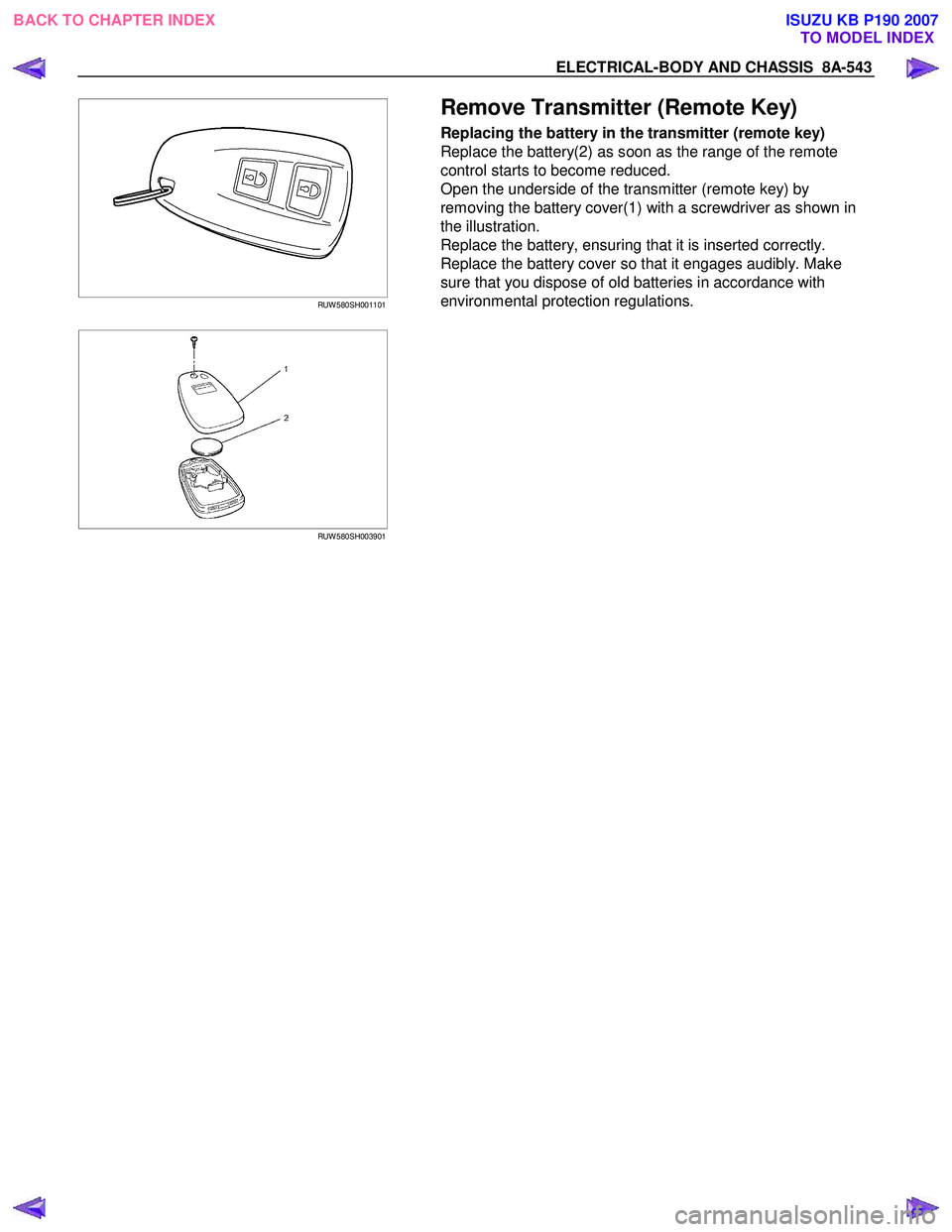
RUW 580SH001101
Remove Transmitter (Remote Key)
Replacing the battery in the transmitter (remote key)
Replace the battery(2) as soon as the range of the remote
control starts to become reduced.
Open the underside of the transmitter (remote key) by
removing the battery cover(1) with a screwdriver as shown in
the illustration.
Replace the battery, ensuring that it is inserted correctly.
Replace the battery cover so that it engages audibly. Make
sure that you dispose of old batteries in accordance with
environmental protection regulations.
RUW 580SH003901
BACK TO CHAPTER INDEX
TO MODEL INDEXISUZU KB P190 2007
Page 5517 of 6020

ELECTRICAL-BODY AND CHASSIS 8A-579
Remote key
Remove Key Assembly
Replacing the battery in the remote control unit
Replace the battery as soon as the range of the remote control
starts to become reduced.
Open the underside of the remote control unit by removing the
battery cover with a screwdriver as shown in the illustration.
Replace the battery, ensuring that it is inserted correctly.
Replace the battery cover so that it engages audibly. The
battery change must be performed within 3 minutes, otherwise
the remote control will have to be reprogrammed. Make sure
that you dispose of old batteries in accordance with
environmental protection regulations.
604RW 055
BACK TO CHAPTER INDEX TO MODEL INDEXISUZU KB P190 2007
Page 5956 of 6020

11B-2 ANTITHEFT SYSTEM
Service Precaution
WARNING: THIS VEHICLE HAS A SUPPLEMENTAL
RESTRAINT SYSTEM (SRS). REFER TO THE SRS
COMPONENT AND WIRING LOCATION VIEW IN
ORDER TO DETERMINE WHETHER YOU ARE
PERFORMING SERVICE ON OR NEAR THE SRS
COMPONENTS OR THE SRS WIRING. WHEN YOU
ARE PERFORMING SERVICE ON OR NEAR THE
SRS COMPONENTS OR THE SRS WIRING, REFER
TO THE SRS SERVICE INFORMATION. FAILURE TO
FOLLOW WARNINGS COULD RESULT IN
POSSIBLE AIR BAG DEPLOYMENT, PERSONAL
INJURY, OR OTHERWISE UNNEEDED SRS SYSTEM
REPAIRS.
CAUTION: Always use the correct fastener in the
proper location. When you replace a fastener, use
ONLY the exact part number for that application.
ISUZU will call out those fasteners that require a
replacement after removal. ISUZU will also call out
the fasteners that require thread lockers or thread
sealant. UNLESS OTHERWISE SPECIFIED, do not
use supplemental coatings (Paints, greases, or
other corrosion inhibitors) on threaded fasteners or
fastener joint interfaces. Generally, such coatings
adversely affect the fastener torque and the joint
clamping force, and may damage the fastener.
When you install fasteners, use the correct
tightening sequence and specifications. Following
these instructions can help you avoid damage to
parts and systems.
General Description
The Antitheft system consists of the four major
components which are Antitheft Control Unit (ACU),
Antitheft horn, key (remote key), and scan tool (Tech-2).
This system can be activated by a correctly
programmed key (remote key) and starter switch is set
to OFF.
This system can be deactivated by a correctly
programmed key (remote key) connected with a
correctly programmed ACU and a correctly
programmed lCU.
W hen the vehicle doors, and engine hood are locked,
the antitheft alarm system is designed to protect your
vehicle and valuables from theft.
Any attempt to forcibly open any door, the engine hood
without using the vehicle key (or remote control) will
cause the hazard lights to flash on and off and the horn
to sound intermittently. This will continue for 30 seconds
(Hazard lamp flash; For 5 minutes) before the system
automatically shuts itself off.
Please operate the door either the key lock or remote
key after closing all doors to arm the alarm system.
Miss waning will be detected when the passenger door
is opened with locked condition and then this door is
closed.
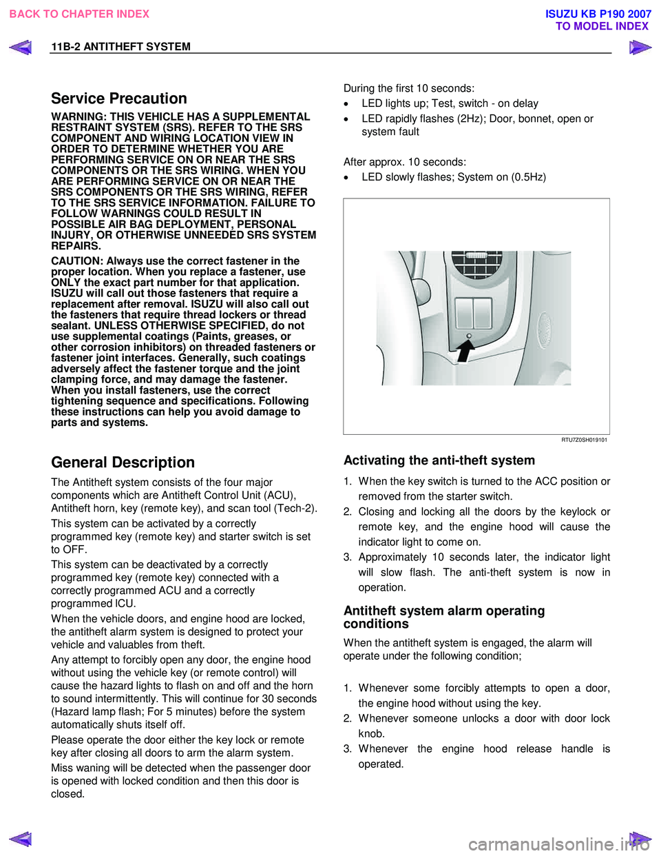
During the first 10 seconds:
• LED lights up; Test, switch - on delay
• LED rapidly flashes (2Hz); Door, bonnet, open or
system fault
After approx. 10 seconds:
• LED slowly flashes; System on (0.5Hz)
RTU7Z0SH019101
Activating the anti-theft system
1. W hen the key switch is turned to the ACC position or
removed from the starter switch.
2. Closing and locking all the doors by the keylock o
r
remote key, and the engine hood will cause the
indicator light to come on.
3. Approximately 10 seconds later, the indicator light will slow flash. The anti-theft system is now in
operation.
Antitheft system alarm operating
conditions
W hen the antitheft system is engaged, the alarm will
operate under the following condition;
1. W henever some forcibly attempts to open a door, the engine hood without using the key.
2. W henever someone unlocks a door with door lock knob.
3. W henever the engine hood release handle is operated.
BACK TO CHAPTER INDEX TO MODEL INDEX
ISUZU KB P190 2007