2007 ISUZU KB P190 flat tire
[x] Cancel search: flat tirePage 573 of 6020

FRONT WHEEL DRIVE 4C1-69
6. FRONT WHEEL SHIMMY
Checkpoint Trouble Cause Countermeasure
Ball joint or bush
Replace the ball joint or bush
Worn
Front alignment
Adjust the front alignment
Adjust or replace
Incorrect
W orn or improperly adjusted
OK
OK NG
NG
NG
OK
W heel bearing
Tighten or replace
Loose or worn
NG
Shock absorber
Replace the shock absorber
Worn
Tire
Replace or adjust the inflation
W orn or improperly inflated
OK NG
NG
OK
Steering unit
BACK TO CHAPTER INDEX
TO MODEL INDEX
ISUZU KB P190 2007
Page 2008 of 6020
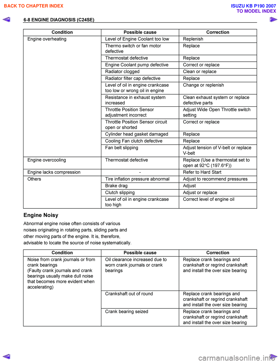
6-8 ENGINE DIAGNOSIS (C24SE)
Condition Possible cause Correction
Engine overheating Level of Engine Coolant too low Replenish
Thermo switch or fan motor
defective Replace
Thermostat
defective Replace
Engine Coolant pump defective Correct or replace
Radiator clogged Clean or replace
Radiator filter cap defective Replace
Level of oil in engine crankcase
too low or wrong oil in engine Change or replenish
Resistance in exhaust system
increased Clean exhaust system or replace
defective parts
Throttle Position Sensor
adjustment incorrect Adjust Wide Open Throttle switch
setting
Throttle Position Sensor circuit
open or shorted Correct or replace
Cylinder head gasket damaged Replace
Cooling Fan clutch defective Replace
Fan belt slipping Adjust tension of V-belt or replace
V-belt
Engine overcooling Thermostat defective Replace (Use a thermostat set to
open at 92 °C (197.6 °F))
Engine lacks compression - Refer to Hard Start
Others Tire inflation pressure abnormal Adjust to recommend pressures
Brake drag Adjust
Clutch slipping Adjust or replace
Level of oil in engine crankcase
too high Correct level of engine oil
Engine Noisy
Abnormal engine noise often consists of various
noises originating in rotating parts, sliding parts and
other moving parts of the engine. It is, therefore,
advisable to locate the source of noise systematically.
Condition Possible cause Correction
Noise from crank journals or from
crank bearings
(Faulty crank journals and crank
bearings usually make dull noise
that becomes more evident when
accelerating) Oil clearance increased due to
worn crank journals or crank
bearings Replace crank bearings and
crankshaft or regrind crankshaft
and install the over size bearing
Crankshaft out of round Replace crank bearings and
crankshaft or regrind crankshaft
and install the over size bearing
Crank bearing seized Replace crank bearings and
crankshaft or regrind crankshaft
and install the over size bearing
BACK TO CHAPTER INDEX
TO MODEL INDEX
ISUZU KB P190 2007
Page 2825 of 6020

Engine Mechanical – V6 Page 6A1–48
Page 6A1–48
2.18 Engine Oil Leak Diagnosis
Introduction
It is important to correctly identify the source of an engine oil leak. For example, a power steering fluid leak or spillage
during servicing can travel across the va lley area of the engine and run-out the weep hole, which is located at the back of
the cylinder block. Failure to correctly identify the source of an engine oil leak can lead to unnecessary replacement of
engine components.
Most fluid leaks can be repaired by repairi ng or replacing the faulty component or resealing the gasket surface. However,
once a leak is identified it is im portant to determine and repair the c ause as well as the leak itself.
Locating and Identifying the Leak
Inspect the leaking fluid and determine whet her it is engine oil, transmission fluid, power steering fluid, brake fluid or
some other fluid. If unsure of the source of the leaking lubricant, a quick check of fluid levels should indicate where the
fluid is coming from, as one or more fluid level should be low.
Visual Inspection
Once the type of leaking fluid has been determined, a visual inspection of the affected system should be performed.
When performing the visual inspection:
1 Bring the vehicle to the normal operating temperature.
2 Park the vehicle over a large s heet of paper or other clean surface.
3 Leave the vehicle idling for 2-3 minut es, then check for dripping fluid.
4 If required, identify the type of fluid leak ing and the approximate location of the leak.
5 Visually inspect the suspected area. A small mirror may assist viewing areas that are difficult to see normally.
6 Check for leaks at all sealing surfaces and fittings.
7 Check for any cracked or damaged components.
8 If the leak cannot be located, completely clean the entire engine and surrounding components, drive the vehicle at
normal operating temperature for several k ilometres and then repeat Steps 3 to 8.
9 If the leak still cannot be located, proceed with either the Powder Method or Black Light and Dye Method as
outlined below.
Powder Method
1 Completely clean the entir e engine and surrounding components.
2 Apply an aerosol type powder (e.g. f oot powder) to the suspected area.
3 Operate the vehicle at normal operating temperature and at varying speeds for several kilometres.
4 Identify the source of the leak from the discoloration of the powder around the suspect components.
5 If required, use a small mirror to assist in vi ewing areas that are difficult to see normally.
6 Refer to Possible Causes for Engine Oil Leaks in this Section, and repair or replace components as required.
Black Light and Dye Method
A black light and die kit Tool No. J28428-E or a commercially av ailable equivalent is available to technicians to aid in
engine oil leak diagnosis. When using a black light and die kit fo r the first time, it is recommended the technician read the
manufacturers instructions prior to using the kit.
1 Add the specified amount of dye, as per manufacturers instructions, into the engine or suspected source of the oil
leak.
2 Operate the vehicle at normal operating temperature and at varying speeds for several kilometres.
3 With the vehicle parked on a flat leve l surface, aim the black light at the suspected component/s. The dyed fluid will
appear as a yellow path leading to the oil leak source
4 Refer to Possible Causes for Engine Oil Leaks in this Section, and repair or replace components as required.
BACK TO CHAPTER INDEX
TO MODEL INDEX
ISUZU KB P190 2007
Page 4804 of 6020
7C-26 CLUTCH
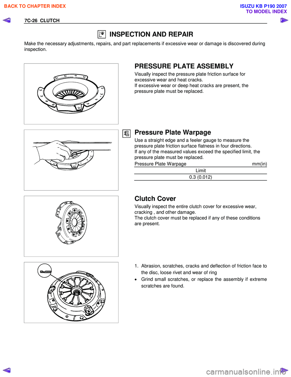
INSPECTION AND REPAIR
Make the necessary adjustments, repairs, and part replacements if excessive wear or damage is discovered during
inspection.
PRESSURE PLATE ASSEMBLY
Visually inspect the pressure plate friction surface for
excessive wear and heat cracks.
If excessive wear or deep heat cracks are present, the
pressure plate must be replaced.
Pressure Plate Warpage
Use a straight edge and a feeler gauge to measure the
pressure plate friction surface flatness in four directions.
If any of the measured values exceed the specified limit, the
pressure plate must be replaced.
Pressure Plate W arpage mm(in)
Limit
0.3 (0.012)
Clutch Cover
Visually inspect the entire clutch cover for excessive wear,
cracking , and other damage.
The clutch cover must be replaced if any of these conditions
are present.
1. Abrasion, scratches, cracks and deflection of friction face to
the disc, loose rivet and wear of ring
• Grind small scratches, or replace the assembly if extreme
scratches are found.
BACK TO CHAPTER INDEX
TO MODEL INDEX
ISUZU KB P190 2007
Page 5111 of 6020
ELECTRICAL-BODY AND CHASSIS 8A-173
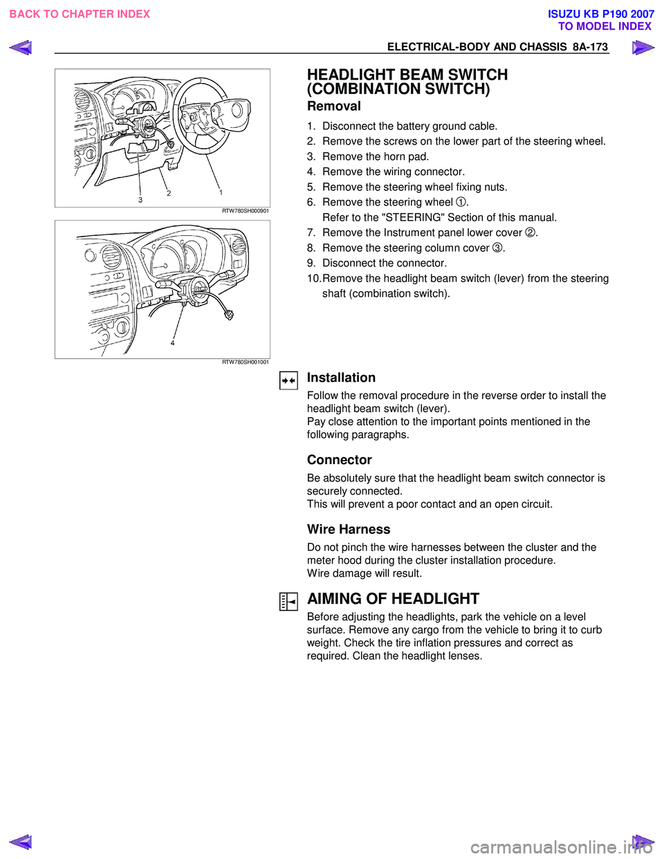
RTW 780SH000901
RTW 780SH001001
HEADLIGHT BEAM SWITCH
(COMBINATION SWITCH)
Removal
1. Disconnect the battery ground cable.
2. Remove the screws on the lower part of the steering wheel.
3. Remove the horn pad.
4. Remove the wiring connector.
5. Remove the steering wheel fixing nuts.
6. Remove the steering wheel
1.
Refer to the "STEERING" Section of this manual.
7. Remove the Instrument panel lower cover
2.
8. Remove the steering column cover
3.
9. Disconnect the connector.
10. Remove the headlight beam switch (lever) from the steering shaft (combination switch).
Installation
Follow the removal procedure in the reverse order to install the
headlight beam switch (lever).
Pay close attention to the important points mentioned in the
following paragraphs.
Connector
Be absolutely sure that the headlight beam switch connector is
securely connected.
This will prevent a poor contact and an open circuit.
Wire Harness
Do not pinch the wire harnesses between the cluster and the
meter hood during the cluster installation procedure.
W ire damage will result.
AIMING OF HEADLIGHT
Before adjusting the headlights, park the vehicle on a level
surface. Remove any cargo from the vehicle to bring it to curb
weight. Check the tire inflation pressures and correct as
required. Clean the headlight lenses.
BACK TO CHAPTER INDEX TO MODEL INDEXISUZU KB P190 2007
Page 5115 of 6020
ELECTRICAL-BODY AND CHASSIS 8A-177
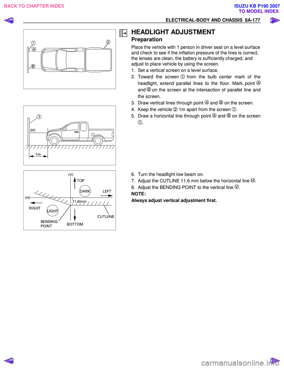
HEADLIGHT ADJUSTMENT
Preparation
Place the vehicle with 1 person in driver seat on a level surface
and check to see if the inflation pressure of the tires is correct,
the lenses are clean, the battery is sufficiently charged, and
adjust to place vehicle by using the screen.
1. Set a vertical screen on a level surface.
2. Toward the screen
1from the bulb center mark of the
headlight, extend parallel lines to the floor. Mark point
A
and B on the screen at the intersection of parallel line and
the screen.
3. Draw vertical lines through point
A and B on the screen.
4. Keep the vehicle 2 1m apart from the screen 1.
5. Draw a horizontal line through point
A and Bon the screen
1.
6. Turn the headlight low beam on.
7. Adjust the CUTLINE 11.6 mm below the horizontal line
H.
8. Adjust the BENDING POINT to the vertical line
V.
NOTE:
Always adjust vertical adjustment first.
BACK TO CHAPTER INDEX TO MODEL INDEXISUZU KB P190 2007
Page 5658 of 6020
SUPPLEMENTAL RESTRAINT SYSTEM 9A-23
Air Bag Assembly Scrapping Procedure
During the course of a vehicle's useful life, certain
situations may arise which will necessitate the disposal
of a live (undeployed) air bag assembly. This
information covers proper procedures for disposing o
f
a live air bag assembly.
Before a live air bag assembly can be disposed of, it
must be deployed.
A live air bag assembly must not
be disposed of through normal refuse channels.
WARNING: FAILURE TO FOLLOW PROPER
SUPPLEMENTAL RESTRAINT SYSTEM (SRS) AIR
BAG ASSEMBLY DISPOSAL PROCEDURES CAN
RESULT IN AIR BAG DEPLOYMENT WHICH MAY
CAUSE PERSONAL INJURY. AN UNDEPLOYED
AIR BAG ASSEMBLY MUST NOT BE DISPOSED
OF THROUGH NORMAL REFUSE CHANNELS.
THE UNDEPLOYED AIR BAG ASSEMBLY
CONTAINS SUBSTANCES THAT CAN CAUSE
SEVERE ILLNESS OR PERSONAL INJURY IF THE
SEALED CONTAINER IS DAMAGED DURING
DISPOSAL. DISPOSAL IN ANY MANNER
INCONSISTENT WITH PROPER PROCEDURES
MAY BE A VIOLATION OF FEDERAL, STATE, AND
/
OR LOCAL LAW.
In situations which require deployment of a live air bag
assembly, deployment may be accomplished inside o
r
outside the vehicle. The method employed depends
upon the final disposition of the particular vehicle, as
noted in “Deployment Outside Vehicle” and
“Deployment Inside Vehicle” in this section.
Deployment Outside Vehicle (Driver Air
Bag Assembly)
Deployment outside the vehicle is proper when the
vehicle is to be returned to service. This includes, fo
r
example, situations in which the vehicle will be
returned to useful service after a functionally o
r
cosmetically deficient air bag assembly is replaced.
Deployment and disposal of a malfunctioning air bag
assembly is, of course, subject to any required
retention period.
For deployment of a live (undeployed) air bag
assembly outside the vehicle, the deployment
procedure must be followed exactly. Always wea
r
safety glasses during this deployment procedure until
a deployed air bag assembly is scrapped or until an
undeployed air bag assembly is shipped. Before
performing the procedures you should be familiar with
servicing the SRS and with proper handling of the ai
r
bag assembly. Procedures should be read fully before
they are performed.
The following procedure requires use of a 5-8840-
2468-06 SRS deployment harness with appropriate
pigtail adapter. Do not attempt the procedure without
a 5-8840-2468-0 adapter.
WARNING: F
AILURE TO FOLLOW PROCEDURES
IN THE ORDER LISTED MAY RESULT IN
PERSONAL INJURY. NEVER CONNECT THE
DEPLOYMENT HARNESS TO ANY POWER
SOURCE BEFORE CONNECTING THE
DEPLOYMENT HARNESS TO THE DRIVER AIR
BAG ASSEMBLY. DEPLOYMENT HARNESS
SHALL REMAIN SHORTED AND NOT BE
CONNECTED TO A POWER SOURCE UNTIL THE
AIR BAG IS TO BE DEPLOYED. THE AIR BAG
ASSEMBLY WILL IMMEDIATELY DEPLOY THE AIR
BAG WHEN A POWER SOURCE IS CONNECTED
TO IT. WEAR SAFETY GLASSES THROUGHOUT
THIS ENTIRE DEPLOYMENT AND DISPOSAL
PROCEDURE.
NOTE: This information applies only to driver air bag
assembly. Refer to “Deployment Outside Vehicle
(Passenger Air Bag assembly)” in this section fo
r
information on passenger air bag assembly scrapping.
1. Turn the ignition switch to “LOCK”, remove the ke
y
and put on safety glasses.
2. Inspect the 5-8840-2468-0 SRS Deployment Harness and appropriate pigtail adapter fo
r
damage. If the harness or pigtail adapter is
damaged, discard and obtain a replacement.
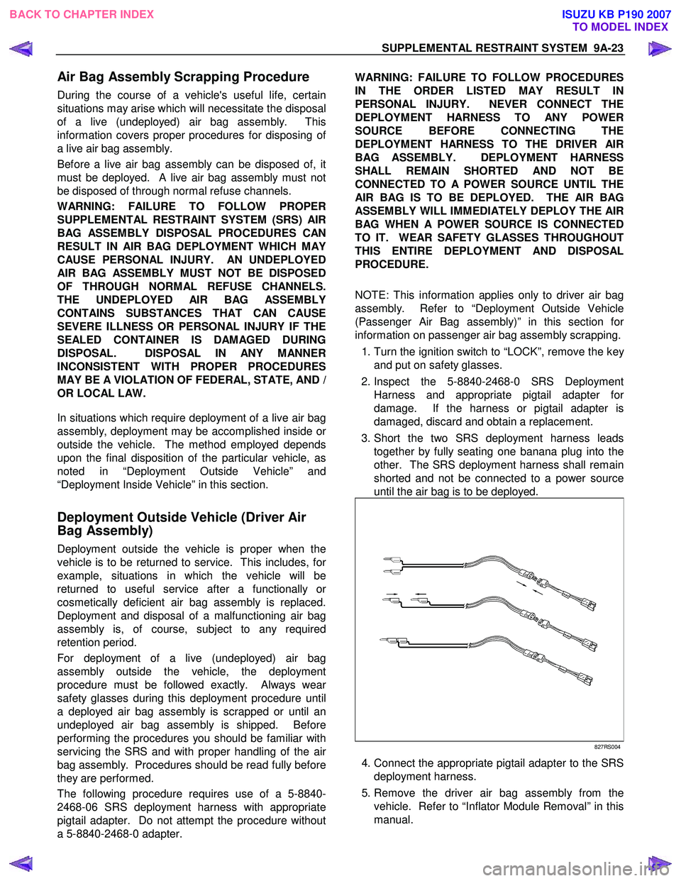
3. Short the two SRS deployment harness leads together by fully seating one banana plug into the
other. The SRS deployment harness shall remain
shorted and not be connected to a power source
until the air bag is to be deployed.
827RS004
4. Connect the appropriate pigtail adapter to the SRS deployment harness.
5. Remove the driver air bag assembly from the vehicle. Refer to “Inflator Module Removal” in this
manual.
BACK TO CHAPTER INDEX TO MODEL INDEXISUZU KB P190 2007
Page 5664 of 6020
SUPPLEMENTAL RESTRAINT SYSTEM 9A-29
5. Strip 13 mm (1/2 inch) of insulation from the yellow
– green and yellow – black wire lead of the
connector.
6. Cut two 900 cm (30 feet) deployment wires from 0.8 mm
2 (18 gauge) or thicker multi–strand wire.
These wires will be used to fabricate the drive
r
deployment harness.
7. Strip 13 mm (1/2 inch) of insulation from both ends of the wires cut in the previous step.
8. Short the wires by twisting together one end from each. Deployment wires shall remain shorted and
not be connected to a power source until the ai
r
bag is to be deployed.
WARNING: FAILURE TO FOLLOW PROCEDURES
IN THE ORDER LISTED COULD RESULT IN
PERSONAL INJURY. NEVER CONNECT
DEPLOYMENT WIRES TO ANY POWER SOURCE
BEFORE CONNECTING DEPLOYMENT WIRES TO
THE AIR BAG ASSEMBLY LEADS. DEPLOYMENT
WIRES SHALL REMAIN SHORTED AND NOT BE
CONNECTED TO A POWER SOURCE UNTIL THE
AIR BAG IS TO BE DEPLOYED. THE AIR BAG
ASSEMBLY WILL IMMEDIATELY DEPLOY THE AIR
BAG WHEN A POWER SOURCE IS CONNECTED
TO IT. WEAR SAFETY GLASSES THROUGHOUT
THIS ENTIRE DEPLOYMENT AND DISPOSAL
PROCEDURE.
9. Twist together one connector wire lead to one deployment wire. The connection should be
mechanically secure.
10. Bend the twisted connection made in the previous step flat and wrap it tightly with electrical tape to
insulate and secure.
11. Twist together, bend and tape the remaining connector wire lead to the remaining deployment
wire.
12. Connect the deployment harness to the driver ai
r
bag assembly yellow connector at the base of the
steering column. Route the deployment harness
out through the driver’s side of the vehicle.
WARNING: DEPLOYMENT WIRES SHALL REMAIN
SHORTED AND NOT BE CONNECTED TO
A
POWER SOURCE UNTIL THE AIR BAG IS TO BE
DEPLOYED.
THE AIR BAG ASSEMBLY WILL IMMEDIATELY
DEPLOY THE AIR BAG WHEN A POWER SOURCE
IS CONNECTED TO IT.
Connecting the deployment wires to the powe
r
source should always be the final step in the ai
r
bag assembly deployment procedure.
Failure to follow procedures in the order listed
could result in personal injury.
13. Disconnect the passenger air bag assembly yello
w
connector located behind the glove box assembly.
14. Cut the passenger air bag assembly harness
connector from the vehicle leaving at least 15 cm
(six inches) of wire at the connector.
15. Strip 13 mm (1/2 inch) of insulation from the blue– white and pink–blue wire lead of the connector.
16. Cut two 900 cm (30 feet) deployment wires from 0.8 mm
2 (18 gauge) or thicker multi–strand wire.
These wires will be used to fabricate the
passenger deployment harness.
17. Strip 13 mm (1/2 inch) of insulation from both ends of the wires cut in the previous step.
18. Short the wires by twisting together one end from each. The deployment wires shall remain shorted
and not be connected to a power source until the
air bag is to be deployed.
WARNING: FAILURE TO FOLLOW PROCEDURES
IN THE ORDER LISTED COULD RESULT IN
PERSONAL INJURY. NEVER CONNECT
DEPLOYMENT WIRES TO ANY POWER SOURCE
BEFORE CONNECTING DEPLOYMENT WIRES TO
THE AIR BAG ASSEMBLY LEADS. DEPLOYMENT
WIRES SHALL REMAIN SHORTED AND NOT BE
CONNECTED TO A POWER SOURCE UNTIL THE
AIR BAG IS TO BE DEPLOYED. THE AIR BAG
ASSEMBLY WILL IMMEDIATELY DEPLOY THE AIR
BAG WHEN A POWER SOURCE IS CONNECTED
TO IT. WEAR SAFETY GLASSES THROUGHOUT
THIS ENTIRE DEPLOYMENT AND DISPOSAL
PROCEDURE.
19. Twist together one connector wire lead to one deployment wire. The connection should be
mechanically secure.
20. Bend the twisted connection made in the previous step flat and wrap it tightly with electrical tape to
insulate and secure.
21. Twist together, bend and tape the remaining connector wire lead to the remaining deployment
wire.
22. Connect the deployment harness to the passenge
r
air bag assembly yellow connector located behind
the glove box assembly. Route the deployment
harness out through the passenger side of the
vehicle.
WARNING: DEPLOYMENT WIRES SHALL REMAIN
SHORTED AND NOT BE CONNECTED TO
A
POWER SOURCE UNTIL THE AIR BAG IS TO BE
DEPLOYED. THE AIR BAG ASSEMBLY WILL
IMMEDIATELY DEPLOY THE AIR BAG WHEN
A
POWER SOURCE IS CONNECTED TO IT.
CONNECTING THE DEPLOYMENT WIRES
SHOULD ALWAYS BE THE FINAL STEP IN THE
AIR BAG ASSEMBLY DEPLOYMENT PROCEDURE.
FAILURE TO FOLLOW PROCEDURES IN THE
ORDER LISTED COULD RESULT IN PERSONAL
INJURY.
BACK TO CHAPTER INDEX TO MODEL INDEXISUZU KB P190 2007