2007 ISUZU KB P190 4WD
[x] Cancel search: 4WDPage 2202 of 6020
6E–32 ENGINE DRIVEABILITY AND EMISSIONS
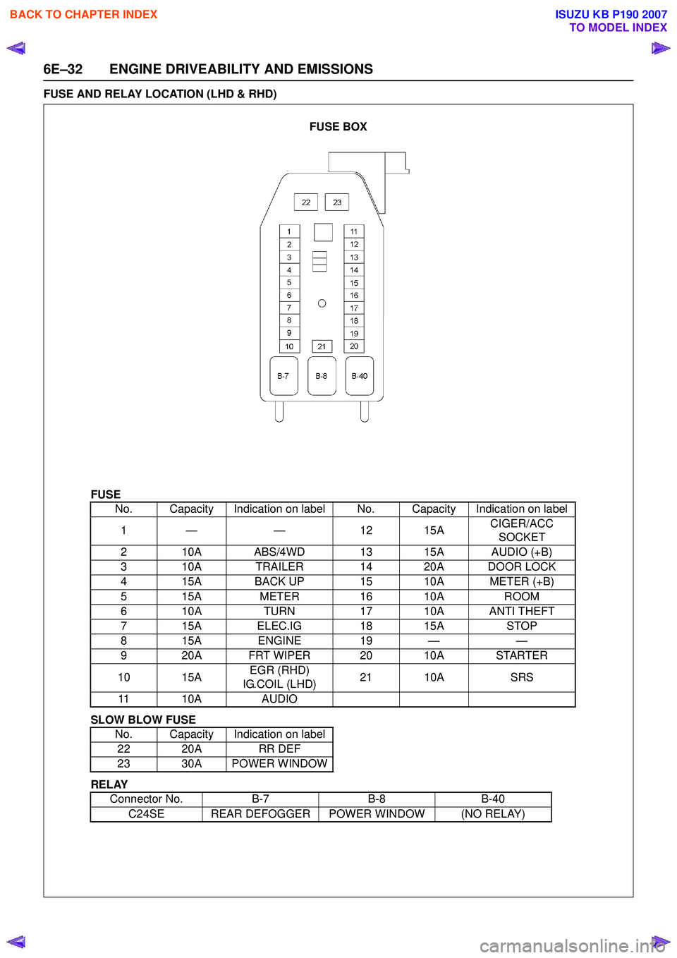
FUSE AND RELAY LOCATION (LHD & RHD)
FUSE
SLOW BLOW FUSE
RELAY No. Capacity Indication on label No. Capacity Indication on label
1— — 1 215A CIGER/ACC
SOCKET
2 10A ABS/4WD 13 15A AUDIO (+B)
3 10A TRAILER 14 20A DOOR LOCK
4 15A BACK UP 15 10A METER (+B)
5 15A METER16 10A ROOM
6 10A TURN17 10A ANTI THEFT
7 15A ELEC.IG 18 15ASTOP
815A ENGINE 19 — —
9 20A FRT WIPER 20 10A STARTER
10 15A EGR (RHD)
IG.COIL (LHD) 21 10A
SRS
11 10A AUDIO
No. Capacity Indication on label 22 20A RR DEF
23 30A POWER WINDOW
Connector No. B-7B-8B-40
C24SE REAR DEFOGGER POWER WINDOW (NO RELAY)
FUSE BOX
BACK TO CHAPTER INDEX
TO MODEL INDEX
ISUZU KB P190 2007
Page 3020 of 6020
Engine Mechanical – V6 Page 6A1–243
Page 6A1–243
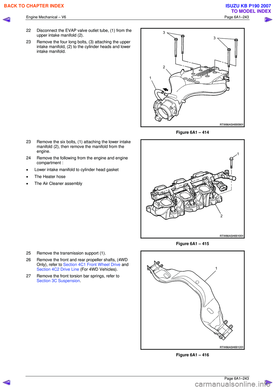
22 Disconnect the EVAP valve outlet tube, (1) from the
upper intake manifold (2).
23 Remove the four long bolts, (3) attaching the upper intake manifold, (2) to the cylinder heads and lower
intake manifold.
Figure 6A1 – 414
23 Remove the six bolts, (1) attaching the lower intake manifold (2), then remove the manifold from the
engine.
24 Remove the following from the engine and engine compartment :
• Lower intake manifold to cylinder head gasket
• The Heater hose
• The Air Cleaner assembly
Figure 6A1 – 415
25 Remove the transmission support (1).
26 Remove the front and rear propeller shafts, (4WD Only), refer to Section 4C1 Front Wheel Drive and
Section 4C2 Drive Line (For 4WD Vehicles).
27 Remove the front torsion bar springs, refer to Section 3C Suspension .
Figure 6A1 – 416
BACK TO CHAPTER INDEX
TO MODEL INDEX
ISUZU KB P190 2007
Page 3021 of 6020
Engine Mechanical – V6 Page 6A1–244
Page 6A1–244
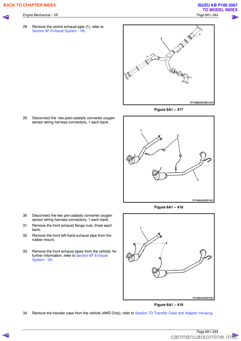
28 Remove the centre exhaust pipe (1), refer to
Section 6F Exhaust System - V6 .
Figure 6A1 – 417
29 Disconnect the two post-catalytic converter oxygen sensor wiring harness connectors, 1 each bank.
Figure 6A1 – 418
30 Disconnect the two pre-catalytic converter oxygen sensor wiring harness connectors, 1 each bank.
31 Remove the front exhaust flange nuts, three each bank.
32 Remove the front left-hand exhaust pipe from the rubber mount.
33 Remove the front exhaust pipes from the vehicle, for further information, refer to Section 6F Exhaust
System - V6 .
Figure 6A1 – 419
34 Remove the transfer case from t he vehicle (4WD Only), refer to Section 7D Transfer Case and Adaptor Housing .
BACK TO CHAPTER INDEX
TO MODEL INDEX
ISUZU KB P190 2007
Page 3766 of 6020
Automatic Transmission – 4L60E – General Information Page 7C1–6
2 General information
The hydra-matic 4L60E automatic transmission is fitted to vehicles with HFV6 engine. The mechanical and internal
electrical operation of the transmission unit is controlled by the transmission control module (TCM) for HFV6 engine.
• For information on the mechanical operation of the transmission, refer to General Motors Powertrain Group
Electronically Controlled Automatic Transmission Technician's Guide.
• For further information on the TCM, refer to 3.1 Transmission Control Module.
2.1 Transmission Control Module – HFV6
Vehicles fitted with a V6 engine and the 4L60E transmission have a new control module and data bus architecture from
previous models. This is due to the introduction of the new V6 engine. Mechanically, the transmission has not changed.
V6 equipped vehicles are now fitted with T42 – Delphi with GMPT software, transmission control module (TCM) to
control all transmission operations. For further information on the TCM and its operation, refer to 3 Transmission Control
Module Operation Overview.
2.2 Transmission Identification
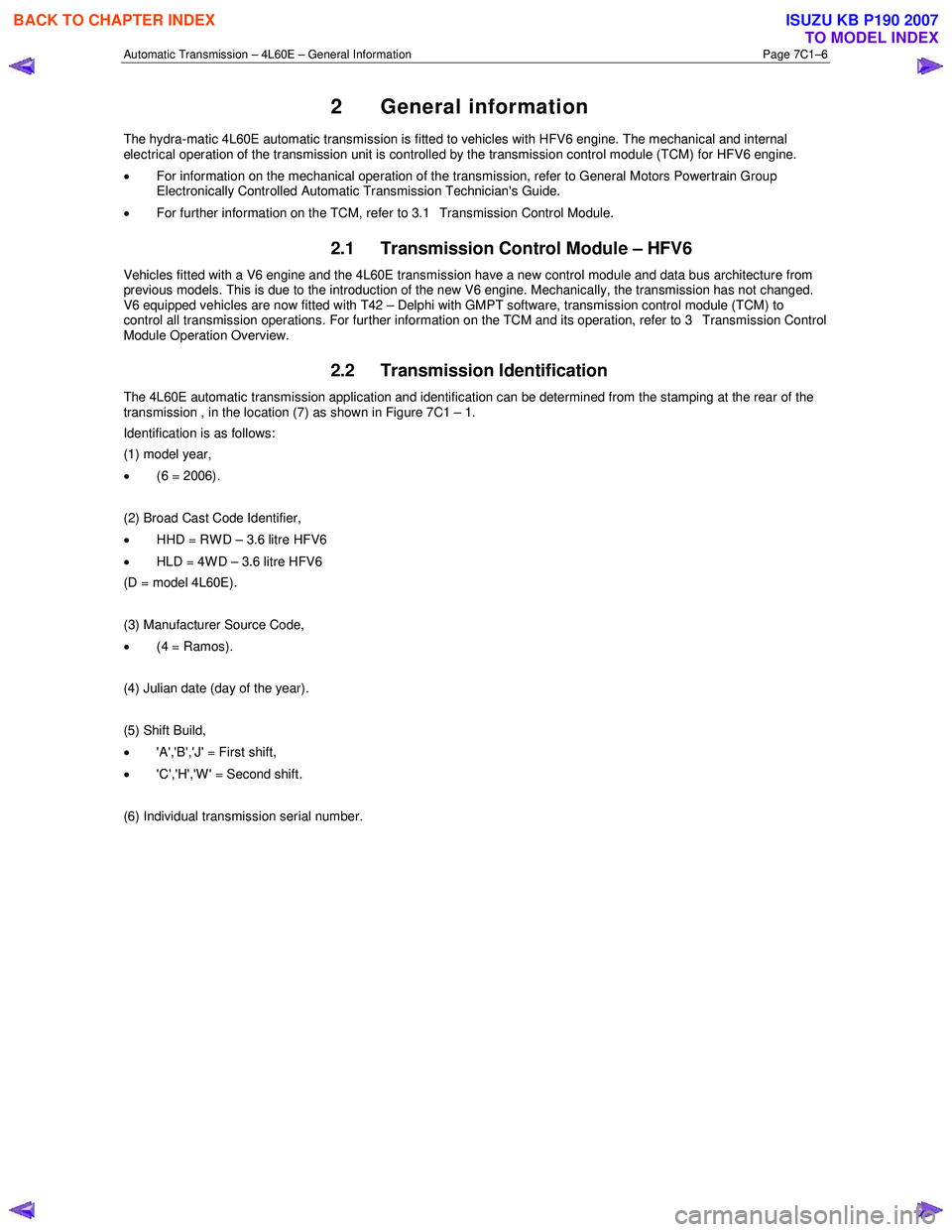
The 4L60E automatic transmission application and identification can be determined from the stamping at the rear of the
transmission , in the location (7) as shown in Figure 7C1 – 1.
Identification is as follows:
(1) model year,
• (6 = 2006).
(2) Broad Cast Code Identifier,
• HHD = RWD – 3.6 litre HFV6
• HLD = 4WD – 3.6 litre HFV6
(D = model 4L60E).
(3) Manufacturer Source Code,
• (4 = Ramos).
(4) Julian date (day of the year).
(5) Shift Build,
• 'A','B','J' = First shift,
• 'C','H','W' = Second shift.
(6) Individual transmission serial number.
BACK TO CHAPTER INDEX
TO MODEL INDEX
ISUZU KB P190 2007
Page 3915 of 6020
Automatic Transmission – 4L60E – On-vehicle Servicing Page 7C4–2
Remove ................................................................................................................................................................. 22
Reinstall ................................................................................................................................................................ 24
3.10 Adaptor Housing, 4WD ........................................................................................................................................ 24
Remove and Reinstall .......................................................................................................................................... 24
3.11 Shift Solenoid Locations ..................................................................................................................................... 25
Location and Identification .................................................................................................... ............................. 25
3.12 1 – 2 Accumulator Assembly ..................................................................................................... ......................... 25
Remove ................................................................................................................................................................. 25
Clean and Inspect ................................................................................................................................................ 26
Reinstall ................................................................................................................................................................ 26
3.13 Control Valve Body Harness ..................................................................................................... .......................... 26
Remove ................................................................................................................................................................. 26
Reinstall ................................................................................................................................................................ 28
3.14 Control Valve Body .............................................................................................................................................. 30
Remove ................................................................................................................................................................. 30
Reinstall ................................................................................................................................................................ 31
3.15 Spacer Plate, Check Balls, Filter Screens and 3 – 4 Accumulator ................................................................ .. 35
Remove ................................................................................................................................................................. 35
Clean and Inspect ................................................................................................................................................ 36
Reinstall ................................................................................................................................................................ 37
3.16 Filler Tube and Breather Hose .................................................................................................. .......................... 39
Remove ................................................................................................................................................................. 39
Reinstall ................................................................................................................................................................ 40
3.17 Transmission Cooler Line/Hose Assemblies ....................................................................................... ............. 41
Remove ................................................................................................................................................................. 41
Reinstall ................................................................................................................................................................ 42
3.18 Transmission Assembly...................................................................................................................................... 43
Remove ................................................................................................................................................................. 43
Reinstall ................................................................................................................................................................ 46
3.19 Transmission Control Module ............................................................................................................................ 47
Remove ................................................................................................................................................................. 47
Reinstall ................................................................................................................................................................ 48
TCM Programming Procedure ...................................................................................................... ...................... 48
4 Specifications .......................................................................................................................................50
5 Torque Wrench Specifications................................................................................................... .........51
6 Special Tools ........................................................................................................................................52
BACK TO CHAPTER INDEX
TO MODEL INDEX
ISUZU KB P190 2007
Page 3931 of 6020
Automatic Transmission – 4L60E – On-vehicle Servicing Page 7C4–18
Ensure the four wheels are off the ground
before performing the starting test.
4 W ith the ignition switched to the ON position, check if the engine can only be started in the Park and Neutral shift selector positions and ensure the back-up lamps illuminate when Reverse is selected. A further minor adjustment
may be required to achieve this state.
NOTE
To gain access to the rear attaching screw (11) it
will be necessary to remove the connector.
5 After the switch has been adjusted, tighten the rear attaching screw (11) to the correct torque specification. Neutral start and back-up lamp switch
attaching screw torque specification .................. 25.0 Nm
6 Reinstall the connector and the CPA securing pin.
7 Remove the switch front attaching screw (1).
8 Install the heat shield (3) and tighten the attaching screws (1 and 2) to the correct torque specification.
Heat shield front attaching screw
torque specification ............................................ 25.0 Nm
Heat shield rear attaching screw torque specification ..............................................9.0 Nm
9 Lower the vehicle to the ground and re-check the operation of the neutral start and back-up lamp switch. The vehicle must start only with the shift selector in the Park or Neutral positions and the back-up lamps should only
illuminate when Reverse is selected.
3.5 Vehicle Speed Sensor
NOTE
For the speed sensor fitted to four wheel drive
vehicles (4WD), refer to 7D Transfer Case and
Adaptor Housing.
Remove
1 Raise the vehicle and support in a safe manner, refer
to 0A General Information for the location of support
points.
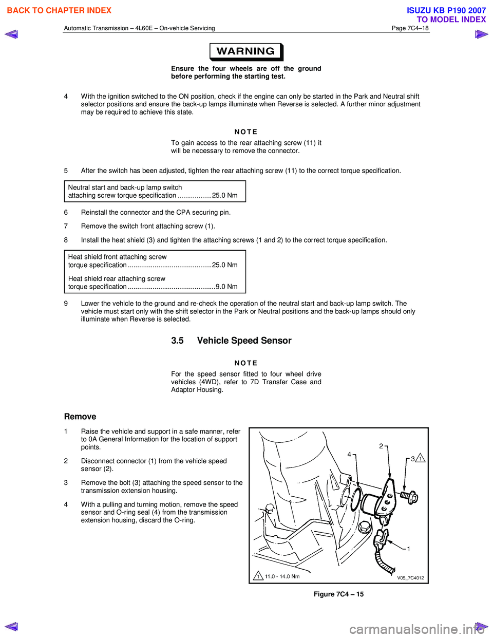
2 Disconnect connector (1) from the vehicle speed sensor (2).
3 Remove the bolt (3) attaching the speed sensor to the transmission extension housing.
4 With a pulling and turning motion, remove the speed sensor and O-ring seal (4) from the transmission
extension housing, discard the O-ring.
Figure 7C4 – 15
BACK TO CHAPTER INDEX
TO MODEL INDEX
ISUZU KB P190 2007
Page 3937 of 6020
Automatic Transmission – 4L60E – On-vehicle Servicing Page 7C4–24
7 Lubricate the outside of a new bush with automatic
transmission fluid to reduce the chance of material
pick-up.
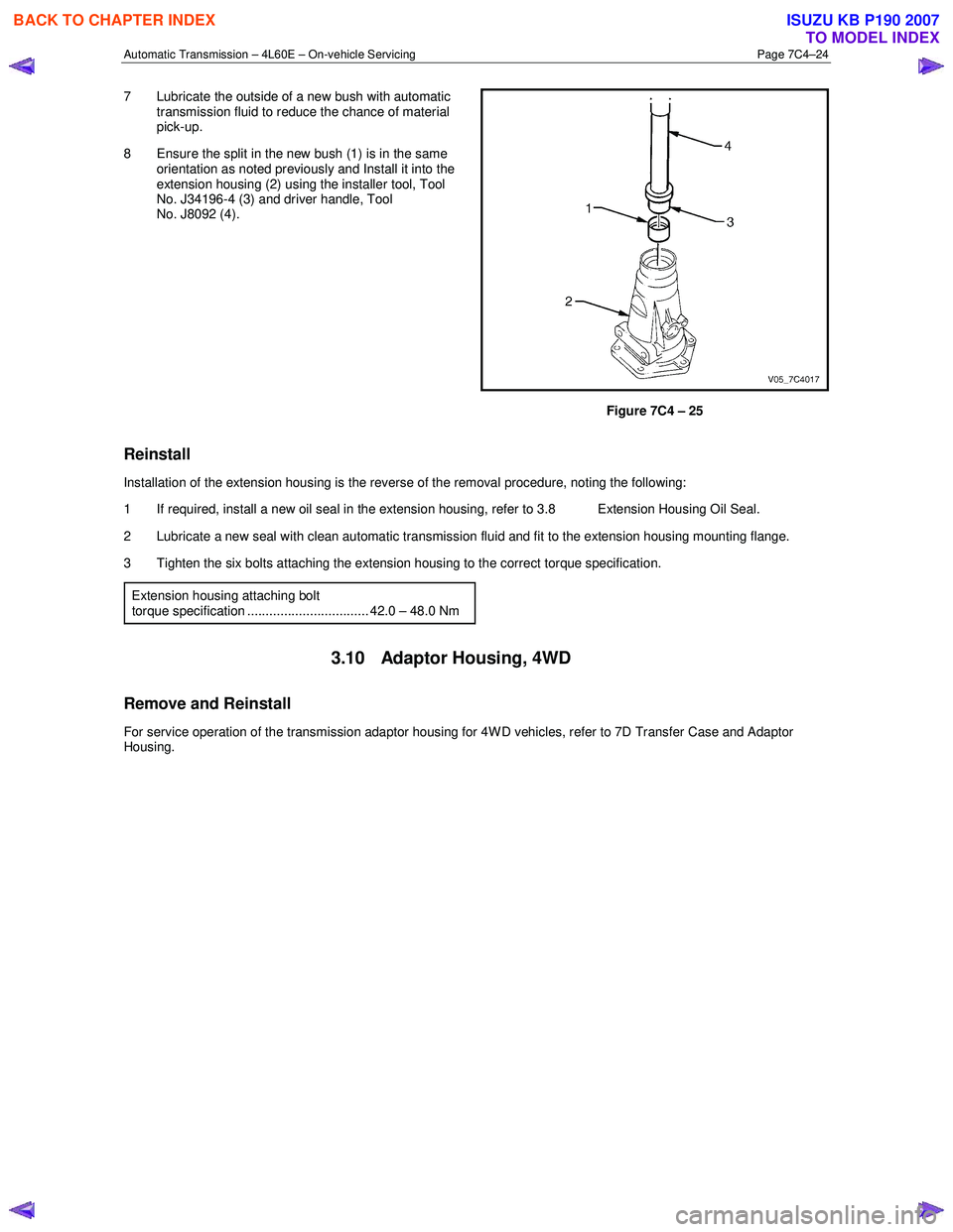
8 Ensure the split in the new bush (1) is in the same orientation as noted previously and Install it into the
extension housing (2) using the installer tool, Tool
No. J34196-4 (3) and driver handle, Tool
No. J8092 (4).
Figure 7C4 – 25
Reinstall
Installation of the extension housing is the reverse of the removal procedure, noting the following:
1 If required, install a new oil seal in the extension housing, refer to 3.8 Extension Housing Oil Seal.
2 Lubricate a new seal with clean automatic transmission fluid and fit to the extension housing mounting flange.
3 Tighten the six bolts attaching the extension housing to the correct torque specification.
Extension housing attaching bolt
torque specification ................................. 42.0 – 48.0 Nm
3.10 Adaptor Housing, 4WD
Remove and Reinstall
For service operation of the transmission adaptor housing for 4W D vehicles, refer to 7D Transfer Case and Adaptor
Housing.
BACK TO CHAPTER INDEX
TO MODEL INDEX
ISUZU KB P190 2007
Page 3956 of 6020
Automatic Transmission – 4L60E – On-vehicle Servicing Page 7C4–43
If the verifier disc does not clip into place, the
quick-connect fitting is not engaged, rectify
as required.
10 As a security check, push and clip each verification disc into place over the quick-connect fittings. If difficulty is experienced, repeat the installation process until the verification disc can be clipped into place over the radiator
quick-connect fitting.
11 Snap the outlet cooler line (4) in the clip (5) of the radiator fan shroud.
12 Ensure the routeing of the cooler lines is correct and there is no fouling of the lines.
13 Tighten the screw attaching the cooler lines bracket to the correct torque specifications.
Transmission cooler lines bracket
attaching screw torque specification .................. 23.0 Nm
14 If required, top up the transmission fluid level (cold).
15 Start the engine and check for any fluid leak at the fittings. If a leak is found, stop the engine and rectify the leak.
16 Check and top up the transmission fluid to the correct level as required, refer to 2.1 Transmission Fluid.
3.18 Transmission Assembly
Remove
Disconnection of the battery affects certain
vehicle electronic systems. Refer to 6D1-3
Battery, before disconnecting the battery.
1 Disconnect the battery ground lead.
2 Raise the vehicle and support in a safe manner, refer to 0A General Information for the location of support points.
3 Remove the heat shield from the neutral start and back-up lamp switch, gently prise the selector cable from the transmission external manual shaft linkage and remove the selector cable from the bracket, refer to
3.3 Selector Cable Assembly.
4 Disconnect the harness connectors from the following:
a Vehicle speed sensor, refer to 3.5 Vehicle Speed Sensor.
b Neutral start and back-up switch, refer to 3.4 Neutral Start and Back-up Lamp Switch.
c For the following on four wheel drive vehicles (4W D), refer to 7D Transfer Case and Adaptor Housing:
• neutral switch,
• 2WD – 4WD shift actuator switch,
• speed sensor.
NOTE
If the battery is connected, avoid turning the
ignition switch to the ON position, as the transfer
case control module (TTCM) must first be
removed (memory to be cleared as Check 4W D
Indicator will light).
5 Remove the following components: a Front and centre exhaust assemblies, refer to 6F Exhaust System.
BACK TO CHAPTER INDEX
TO MODEL INDEX
ISUZU KB P190 2007