Page 4931 of 6020

TRANSFER CONTROL SYSTEM 7D1-57
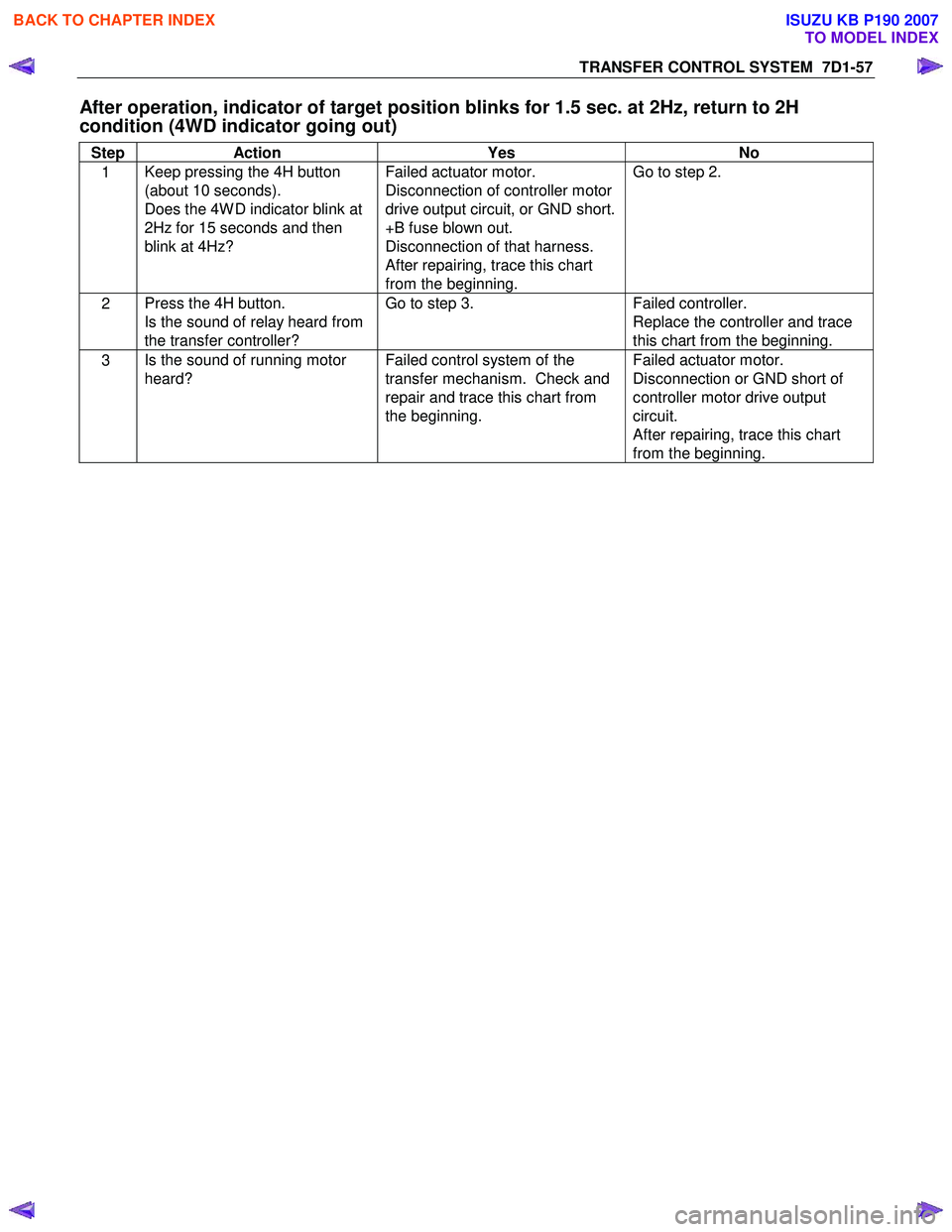
After operation, indicator of target position blinks for 1.5 sec. at 2Hz, return to 2H
condition (4WD indicator going out)
Step Action Yes No
1 Keep pressing the 4H button
(about 10 seconds).
Does the 4W D indicator blink at
2Hz for 15 seconds and then
blink at 4Hz? Failed actuator motor.
Disconnection of controller motor
drive output circuit, or GND short.
+B fuse blown out.
Disconnection of that harness.
After repairing, trace this chart
from the beginning. Go to step 2.
2
Press the 4H button.
Is the sound of relay heard from
the transfer controller? Go to step 3.
Failed controller.
Replace the controller and trace
this chart from the beginning.
3 Is the sound of running motor
heard? Failed control system of the
transfer mechanism. Check and
repair and trace this chart from
the beginning. Failed actuator motor.
Disconnection or GND short of
controller motor drive output
circuit.
After repairing, trace this chart
from the beginning.
BACK TO CHAPTER INDEX
TO MODEL INDEX
ISUZU KB P190 2007
Page 4932 of 6020

7D1-58 TRANSFER CONTROL SYSTEM
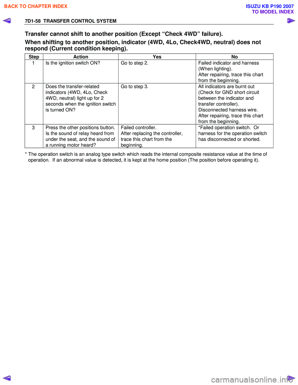
Transfer cannot shift to another position (Except “Check 4WD” failure).
When shifting to another position, indicator (4WD, 4Lo, Check4WD, neutral) does not
respond (Current condition keeping).
Step Action Yes No
1 Is the ignition switch ON? Go to step 2.
Failed indicator and harness
(W hen lighting).
After repairing, trace this chart
from the beginning.
2 Does the transfer-related
indicators (4W D, 4Lo, Check
4W D, neutral) light up for 2
seconds when the ignition switch
is turned ON? Go to step 3.
All indicators are burnt out
(Check for GND short circuit
between the indicator and
transfer controller).
Disconnected harness wire.
After repairing, trace this chart
from the beginning.
3 Press the other positions button.
Is the sound of relay heard from
under the seat, and the sound of
a running motor heard? Failed controller.
After replacing the controller,
trace this chart from the
beginning. *Failed operation switch. Or
harness for the operation switch
has disconnected or shorted.
* The operation switch is an analog type switch which reads the internal composite resistance value at the time of operation. If an abnormal value is detected, it is kept at the home position (The position before operating it).
BACK TO CHAPTER INDEX
TO MODEL INDEX
ISUZU KB P190 2007
Page 4933 of 6020

TRANSFER CONTROL SYSTEM 7D1-59
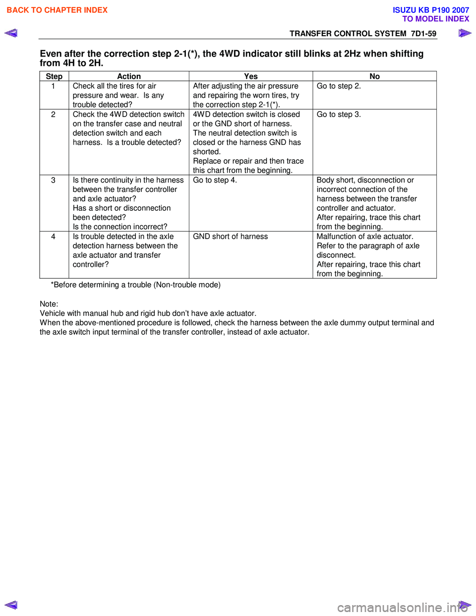
Even after the correction step 2-1(*), the 4WD indicator still blinks at 2Hz when shifting
from 4H to 2H.
Step Action Yes No
1 Check all the tires for air
pressure and wear. Is any
trouble detected? After adjusting the air pressure
and repairing the worn tires, try
the correction step 2-1(*). Go to step 2.
2
Check the 4W D detection switch
on the transfer case and neutral
detection switch and each
harness. Is a trouble detected? 4W D detection switch is closed
or the GND short of harness.
The neutral detection switch is
closed or the harness GND has
shorted.
Replace or repair and then trace
this chart from the beginning. Go to step 3.
3
Is there continuity in the harness
between the transfer controller
and axle actuator?
Has a short or disconnection
been detected?
Is the connection incorrect? Go to step 4.
Body short, disconnection or
incorrect connection of the
harness between the transfer
controller and actuator.
After repairing, trace this chart
from the beginning.
4 Is trouble detected in the axle
detection harness between the
axle actuator and transfer
controller? GND short of harness
Malfunction of axle actuator.
Refer to the paragraph of axle
disconnect.
After repairing, trace this chart
from the beginning.
*Before determining a trouble (Non-trouble mode)
Note:
Vehicle with manual hub and rigid hub don’t have axle actuator.
W hen the above-mentioned procedure is followed, check the harness between the axle dummy output terminal and
the axle switch input terminal of the transfer controller, instead of axle actuator.
BACK TO CHAPTER INDEX
TO MODEL INDEX
ISUZU KB P190 2007
Page 4971 of 6020
ELECTRICAL-BODY AND CHASSIS 8A-33
FUSE LOCATION
RHD/LHD
FUSE
NO. Capacity Indication on label NO. Capacity Indication on label
C 1 10A STARTER C 1110A AUDIO
C2
C
12 20A CIGAR/ACC SOCKET
10A TRAILER *3 C 13 15A AUDIO (+B)
C3 10A ELEC IG C 14 10A METER
C4 10A TURN C 15 15A STOP
C5 10A ABS/4WD C 16
C6 10A ENGINE C 17 10A ROOM
10A ECU *4 C19 10A METER (+B)
C7 15A TCM/IG COIL/ C2 120A DOOR LOCK
10A GLOW ENGINE *4 C22
C8 10A SRS 10A ANTI THEFT *5
C9 20A FRT WIPER
C10 15A BACKUP
SLOW BLOW FUSE
NO. Capacity Indication on label
C 18 20A RR DEF
C20 30A POWER WINDOW
FUSE BOX
*3 … HFV6 (AUSTRALIA)
*4 … HFV6
*5 … 4JJ 1-TC (EUROPE)
BACK TO CHAPTER INDEX
TO MODEL INDEXISUZU KB P190 2007
Page 5451 of 6020
ELECTRICAL-BODY AND CHASSIS 8A-513
2WD-4WD Switch
REMOVAL AND INSTALLATION
RTW 780SH002001
Removal
1. Remove the center cluster ASM
2. Disconnect the connector.
3. Remove the 2WD-4WD switch.
Installation
To install, follow the removal steps in the reverse order.
BACK TO CHAPTER INDEX TO MODEL INDEXISUZU KB P190 2007