2007 ISUZU KB P190 cruise control
[x] Cancel search: cruise controlPage 3709 of 6020
Powertrain Interface Module – V6 Page 6E1–48
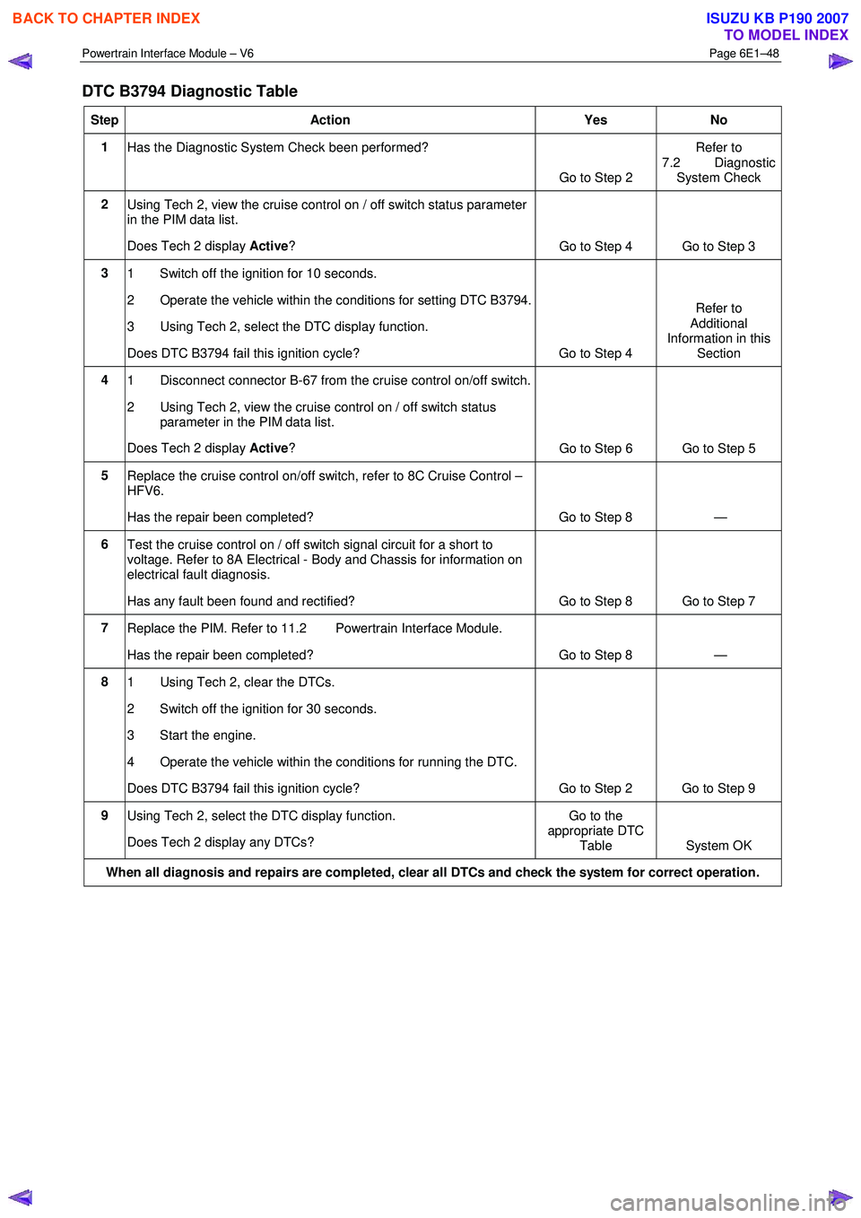
DTC B3794 Diagnostic Table
Step Action Yes No
1
Has the Diagnostic System Check been performed?
Go to Step 2 Refer to
7.2 Diagnostic System Check
2 Using Tech 2, view the cruise control on / off switch status parameter
in the PIM data list.
Does Tech 2 display Active?
Go to Step 4 Go to Step 3
3
1 Switch off the ignition for 10 seconds.
2 Operate the vehicle within the conditions for setting DTC B3794.
3 Using Tech 2, select the DTC display function.
Does DTC B3794 fail this ignition cycle? Go to Step 4 Refer to
Additional
Information in this Section
4 1 Disconnect connector B-67 from the cruise control on/off switch.
2 Using Tech 2, view the cruise control on / off switch status parameter in the PIM data list.
Does Tech 2 display Active?
Go to Step 6 Go to Step 5
5 Replace the cruise control on/off switch, refer to 8C Cruise Control –
HFV6.
Has the repair been completed? Go to Step 8 —
6 Test the cruise control on / off switch signal circuit for a short to
voltage. Refer to 8A Electrical - Body and Chassis for information on
electrical fault diagnosis.
Has any fault been found and rectified? Go to Step 8 Go to Step 7
7 Replace the PIM. Refer to 11.2 Powertrain Interface Module.
Has the repair been completed? Go to Step 8 —
8 1 Using Tech 2, clear the DTCs.
2 Switch off the ignition for 30 seconds.
3 Start the engine.
4 Operate the vehicle within the conditions for running the DTC.
Does DTC B3794 fail this ignition cycle? Go to Step 2 Go to Step 9
9 Using Tech 2, select the DTC display function.
Does Tech 2 display any DTCs? Go to the
appropriate DTC Table System OK
When all diagnosis and repairs are completed, clear all DTCs and check the system for correct operation.
BACK TO CHAPTER INDEX
TO MODEL INDEX
ISUZU KB P190 2007
Page 3726 of 6020
Powertrain Interface Module – V6 Page 6E1–65
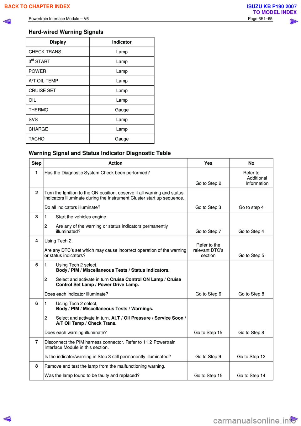
Hard-wired Warning Signals
Display Indicator
CHECK TRANS Lamp
3rd START Lamp
POW ER Lamp
A/T OIL TEMP Lamp
CRUISE SET Lamp
OIL Lamp
THERMO Gauge
SVS Lamp
CHARGE Lamp
TACHO Gauge
Warning Signal and Status Indicator Diagnostic Table
Step Action Yes No
1
Has the Diagnostic System Check been performed?
Go to Step 2 Refer to
Additional
Information
2 Turn the Ignition to the ON position, observe if all warning and status
indicators illuminate during the Instrument Cluster start up sequence.
Do all indicators illuminate? Go to Step 3 Go to step 4
3 1 Start the vehicles engine.
2 Are any of the warning or status indicators permanently illuminated? Go to Step 7 Go to Step 4
4 Using Tech 2.
Are any DTC’s set which may cause incorrect operation of the warning
or status indicators? Refer to the
relevant DTC’s section Go to Step 5
5
1 Using Tech 2 select,
Body / PIM / Miscellaneous Tests / Status Indicators.
2 Select and activate in turn Cruise Control ON Lamp / Cruise
Control Set Lamp / Power Drive Lamp.
Does each indicator illuminate? Go to Step 6 Go to Step 8
6
1 Using Tech 2 select,
Body / PIM / Miscellaneous Tests / Warnings.
2 Select and activate in turn, ALT / Oil Pressure / Service Soon /
A/T Oil Temp / Check Trans.
Does each warning illuminate? Go to Step 15 Go to Step 8
7 Disconnect the PIM harness connector. Refer to 11.2 Powertrain
Interface Module in this section.
Is the indicator/warning in Step 3 still permanently illuminated? Go to Step 9 Go to Step 12
8 Remove and test the lamp from the malfunctioning warning.
W as the lamp found to be faulty and replaced? Go to Step 15 Go to Step 14
BACK TO CHAPTER INDEX
TO MODEL INDEX
ISUZU KB P190 2007
Page 3742 of 6020
Powertrain Interface Module – V6 Page 6E1–81
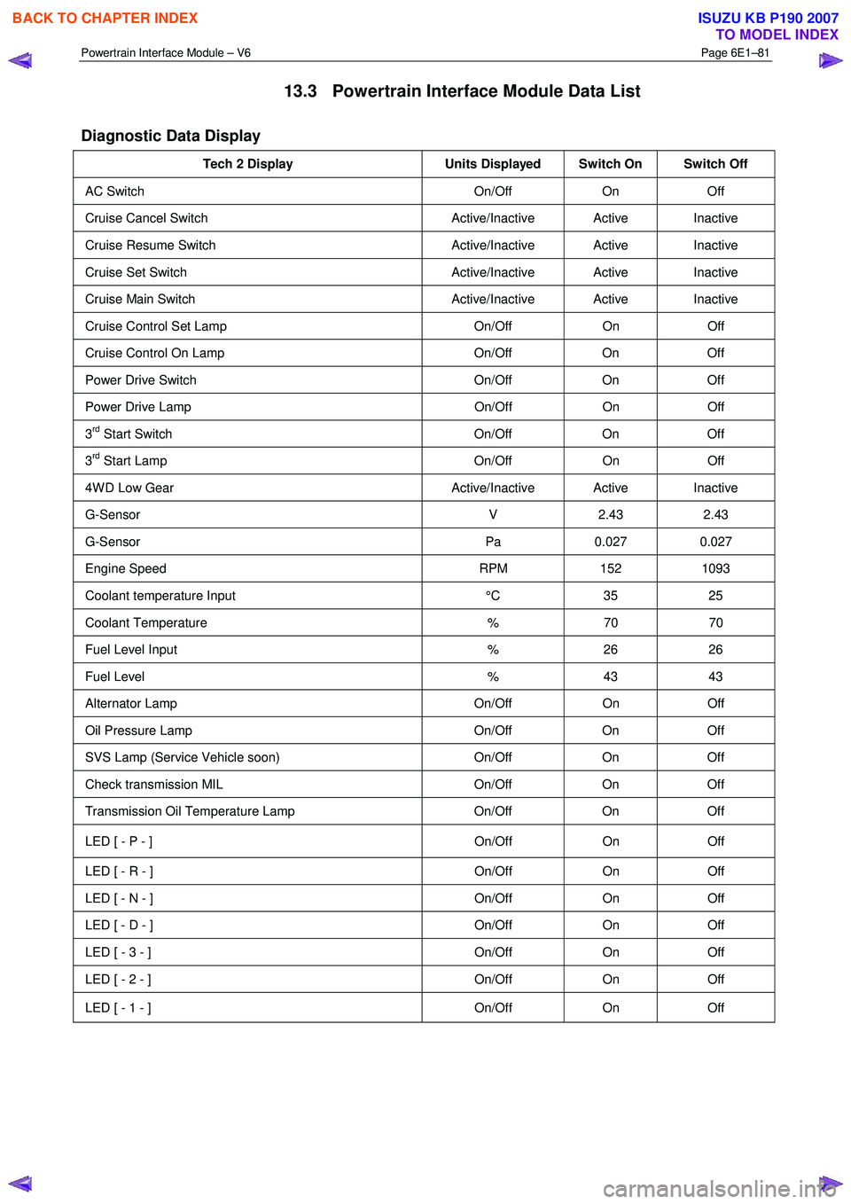
13.3 Powertrain Interface Module Data List
Diagnostic Data Display
Tech 2 Display Units Displayed Switch On Switch Off
AC Switch On/Off On Off
Cruise Cancel Switch Active/Inactive Active Inactive
Cruise Resume Switch Active/Inactive Active Inactive
Cruise Set Switch Active/Inactive Active Inactive
Cruise Main Switch Active/Inactive Active Inactive
Cruise Control Set Lamp On/Off On Off
Cruise Control On Lamp On/Off On Off
Power Drive Switch On/Off On Off
Power Drive Lamp On/Off On Off
3rd Start Switch On/Off On Off
3rd Start Lamp On/Off On Off
4W D Low Gear Active/Inactive Active Inactive
G-Sensor V 2.43 2.43
G-Sensor Pa 0.027 0.027
Engine Speed RPM 152 1093
Coolant temperature Input °C 35 25
Coolant Temperature % 70 70
Fuel Level Input % 26 26
Fuel Level % 43 43
Alternator Lamp On/Off On Off
Oil Pressure Lamp On/Off On Off
SVS Lamp (Service Vehicle soon) On/Off On Off
Check transmission MIL On/Off On Off
Transmission Oil Temperature Lamp On/Off On Off
LED [ - P - ] On/Off On Off
LED [ - R - ] On/Off On Off
LED [ - N - ] On/Off On Off
LED [ - D - ] On/Off On Off
LED [ - 3 - ] On/Off On Off
LED [ - 2 - ] On/Off On Off
LED [ - 1 - ] On/Off On Off
BACK TO CHAPTER INDEX
TO MODEL INDEX
ISUZU KB P190 2007
Page 3743 of 6020
Powertrain Interface Module – V6 Page 6E1–82
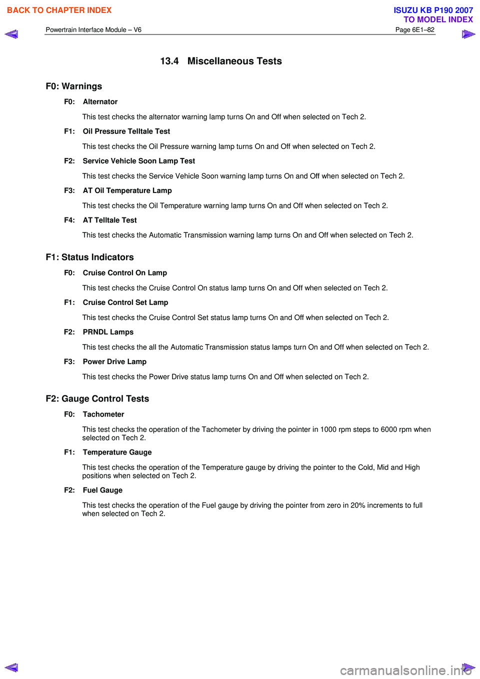
13.4 Miscellaneous Tests
F0: Warnings
F0: Alternator
This test checks the alternator warning lamp turns On and Off when selected on Tech 2.
F1: Oil Pressure Telltale Test
This test checks the Oil Pressure warning lamp turns On and Off when selected on Tech 2.
F2: Service Vehicle Soon Lamp Test
This test checks the Service Vehicle Soon warning lamp turns On and Off when selected on Tech 2.
F3: AT Oil Temperature Lamp
This test checks the Oil Temperature warning lamp turns On and Off when selected on Tech 2.
F4: AT Telltale Test
This test checks the Automatic Transmission warning lamp turns On and Off when selected on Tech 2.
F1: Status Indicators
F0: Cruise Control On Lamp
This test checks the Cruise Control On status lamp turns On and Off when selected on Tech 2.
F1: Cruise Control Set Lamp
This test checks the Cruise Control Set status lamp turns On and Off when selected on Tech 2.
F2: PRNDL Lamps
This test checks the all the Automatic Transmission status lamps turn On and Off when selected on Tech 2.
F3: Power Drive Lamp
This test checks the Power Drive status lamp turns On and Off when selected on Tech 2.
F2: Gauge Control Tests
F0: Tachometer
This test checks the operation of the Tachometer by driving the pointer in 1000 rpm steps to 6000 rpm when
selected on Tech 2.
F1: Temperature Gauge
This test checks the operation of the Temperature gauge by driving the pointer to the Cold, Mid and High
positions when selected on Tech 2.
F2: Fuel Gauge
This test checks the operation of the Fuel gauge by driving the pointer from zero in 20% increments to full when selected on Tech 2.
BACK TO CHAPTER INDEX
TO MODEL INDEX
ISUZU KB P190 2007
Page 3761 of 6020
Automatic Transmission – 4L60E – General Information Page 7C1–1
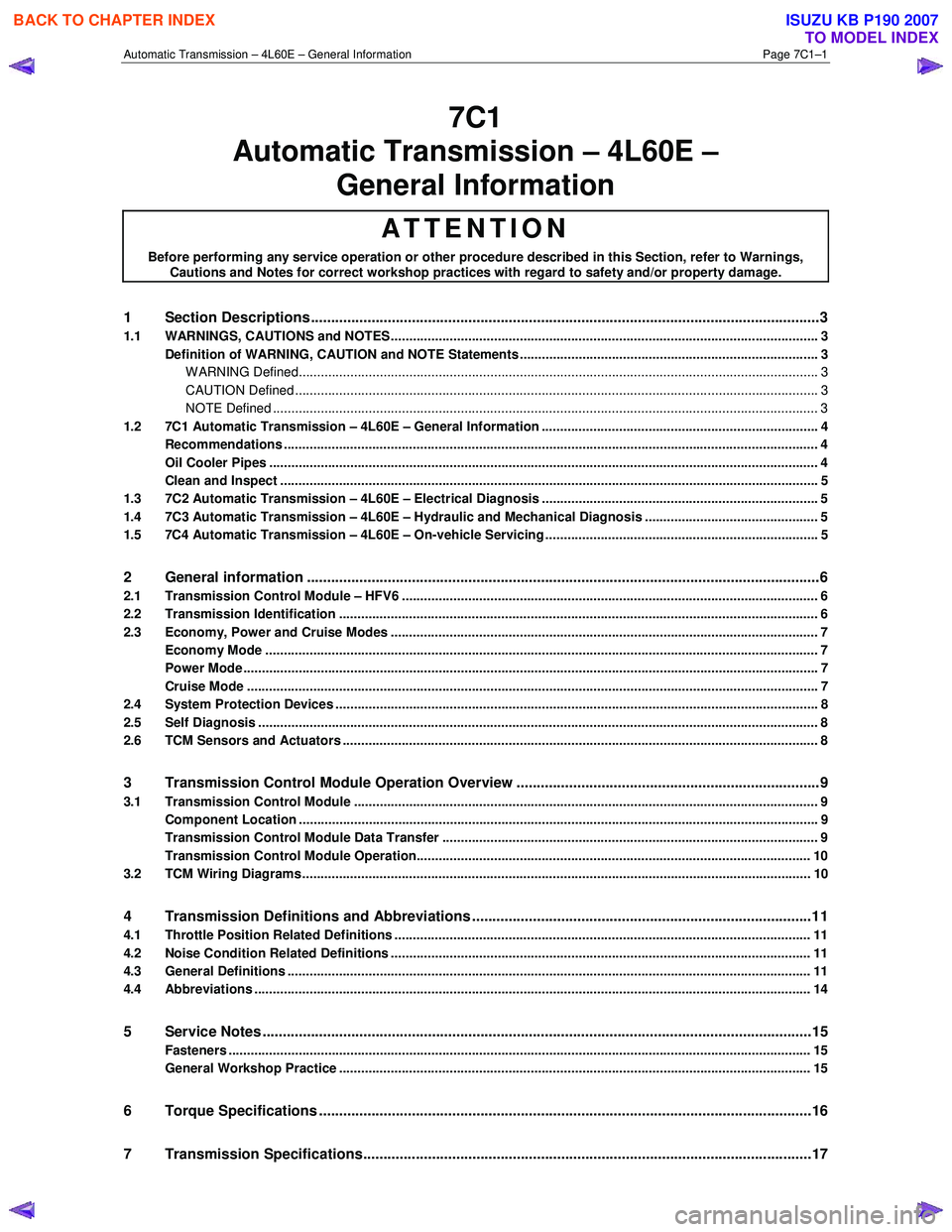
7C1
Automatic Transmission – 4L60E –
General Information
ATTENTION
Before performing any service operation or other procedure described in this Section, refer to Warnings, Cautions and Notes for correct workshop practices with regard to safety and/or property damage.
1 Section Descriptions ........................................................................................................... ...................3
1.1 WARNINGS, CAUTIONS and NOTES................................................................................................... ................. 3
Definition of WARNING, CAUTION and NOTE Statements ............................................................................. .... 3
WARNING Defined............................................................................................................................................. 3
CAUTION Defined .............................................................................................................................................. 3
NOTE Defined .................................................................................................................................................... 3
1.2 7C1 Automatic Transmission – 4L60E – General Information ....................................................................... .... 4
Recommendations ................................................................................................................................................. 4
Oil Cooler Pipes ..................................................................................................................................................... 4
Clean and Inspect .............................................................................................................. .................................... 5
1.3 7C2 Automatic Transmission – 4L60E – Electrical Diagnosis ...................................................................... ..... 5
1.4 7C3 Automatic Transmission – 4L60E – Hydraulic and Mechanical Diagnosis ............................................... 5
1.5 7C4 Automatic Transmission – 4L60E – On-vehicle Servicing ...................................................................... .... 5
2 General information ...............................................................................................................................6
2.1 Transmission Control Module – HFV6 ............................................................................................. .................... 6
2.2 Transmission Identification .................................................................................................................................. 6
2.3 Economy, Power and Cruise Modes .................................................................................................................... 7
Economy Mode ...................................................................................................................................................... 7
Power Mode ............................................................................................................................................................ 7
Cruise Mode ........................................................................................................................................................... 7
2.4 System Protection Devices ...................................................................................................... ............................. 8
2.5 Self Diagnosis ........................................................................................................................................................ 8
2.6 TCM Sensors and Actuators ................................................................................................................................. 8
3 Transmission Control Module Operation Overview ...........................................................................9
3.1 Transmission Control Module .............................................................................................................................. 9
Component Location ............................................................................................................. ................................ 9
Transmission Control Module Data Transfer ...................................................................................... ................ 9
Transmission Control Module Operation........................................................................................................... 10
3.2 TCM Wiring Diagrams.......................................................................................................................................... 10
4 Transmission Definitions and Abbreviations ....................................................................................1 1
4.1 Throttle Position Related Definitions ................................................................................................................. 11
4.2 Noise Condition Related Definitions ............................................................................................ ...................... 11
4.3 General Definitions .............................................................................................................................................. 11
4.4 Abbreviations ....................................................................................................................................................... 14
5 Service Notes ........................................................................................................................................15
Fasteners .............................................................................................................................................................. 15
General Workshop Practice ................................................................................................................................ 15
6 Torque Specifications .......................................................................................................... ................16
7 Transmission Specifications.................................................................................................... ...........17
BACK TO CHAPTER INDEX
TO MODEL INDEX
ISUZU KB P190 2007
Page 3767 of 6020
Automatic Transmission – 4L60E – General Information Page 7C1–7
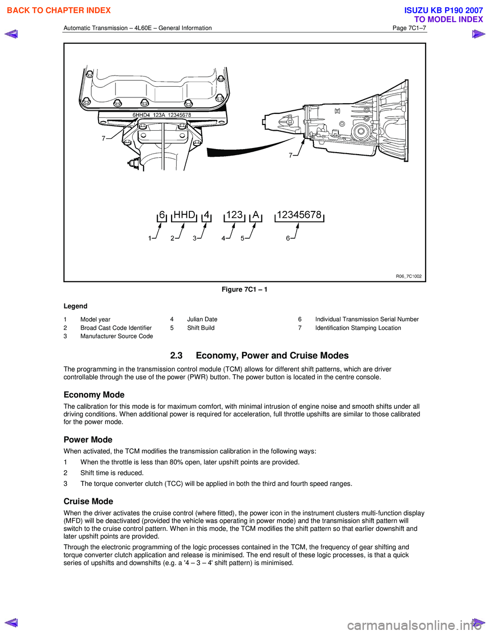
Figure 7C1 – 1
Legend
1 Model year
2 Broad Cast Code Identifier
3 Manufacturer Source Code 4 Julian Date
5 Shift Build 6 Individual Transmission Serial Number
7 Identification Stamping Location
2.3 Economy, Power and Cruise Modes
The programming in the transmission control module (TCM) allows for different shift patterns, which are driver
controllable through the use of the power (PWR) button. The power button is located in the centre console.
Economy Mode
The calibration for this mode is for maximum comfort, with minimal intrusion of engine noise and smooth shifts under all
driving conditions. When additional power is required for acceleration, full throttle upshifts are similar to those calibrated
for the power mode.
Power Mode
When activated, the TCM modifies the transmission calibration in the following ways:
1 When the throttle is less than 80% open, later upshift points are provided.
2 Shift time is reduced.
3 The torque converter clutch (TCC) will be applied in both the third and fourth speed ranges.
Cruise Mode
When the driver activates the cruise control (where fitted), the power icon in the instrument clusters multi-function display
(MFD) will be deactivated (provided the vehicle was operating in power mode) and the transmission shift pattern will
switch to the cruise control pattern. When in this mode, the TCM modifies the shift pattern so that earlier downshift and
later upshift points are provided.
Through the electronic programming of the logic processes contained in the TCM, the frequency of gear shifting and
torque converter clutch application and release is minimised. The end result of these logic processes, is that a quick
series of upshifts and downshifts (e.g. a '4 – 3 – 4' shift pattern) is minimised.
BACK TO CHAPTER INDEX
TO MODEL INDEX
ISUZU KB P190 2007
Page 3769 of 6020
Automatic Transmission – 4L60E – General Information Page 7C1–9
3 Transmission Control Module
Operation Overview
3.1 Transmission Control Module
W ith the introduction of the new HFV6 engine, the powertrain architecture has been redesigned to accommodate this
introduction. W ith this design, a new bus architecture and protocol has also been introduced. The new bus connects the
following modules:
• engine control module (ECM),
• transmission control module (TCM),
• powertrain interface module (PIM) and
• ABS module.
The protocol used to communicate between these modules is called General Motors Local Area Network (GM LAN)
which is based on Controller Area Network (CAN) communication protocol. For further information on GM LAN protocol
and data bus structure, refer to 6E1 Powertrain Interface Module – V6.
Component Location
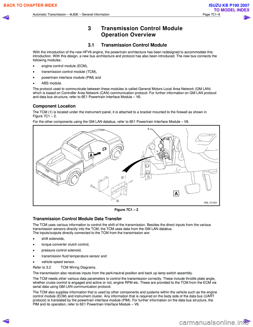
The TCM (1) is located under the instrument panel, it is attached to a bracket mounted to the firewall as shown in
Figure 7C1 – 2.
For the other components using the GM LAN databus, refer to 6E1 Powertrain Interface Module – V6.
Figure 7C1 – 2
Transmission Control Module Data Transfer
The TCM uses various information to control the shift of the transmission. Besides the direct inputs from the various
transmission sensors directly into the TCM, the TCM uses data from the GM LAN databus.
The inputs/outputs directly connected to the TCM from the transmission are:
• shift solenoids,
• torque converter clutch control,
• pressure control solenoid,
• transmission fluid temperature sensor and
• vehicle speed sensor.
Refer to 3.2 TCM Wiring Diagrams.
The transmission also receives inputs from the park/neutral position and back up lamp switch assembly.
The TCM needs other various data parameters to control the transmission correctly. These include throttle plate angle,
whether cruise control is engaged and active or not, engine RPM etc. These are provided to the TCM from the ECM via
serial data using GM LAN communication protocol.
The TCM also supplies information that is used by other components and systems within the vehicle such as the engine
control module (ECM) and instrument cluster. Any information that is required on the body side of the data bus (UART
protocol) is translated by the powertrain interface module (PIM). For further information on the data bus structure, the
PIM and its operation, refer to 6E1 Powertrain Interface Module – V6.
BACK TO CHAPTER INDEX
TO MODEL INDEX
ISUZU KB P190 2007
Page 3803 of 6020
Automatic Transmission – 4L60E – Electrical Diagnosis Page 7C2–17
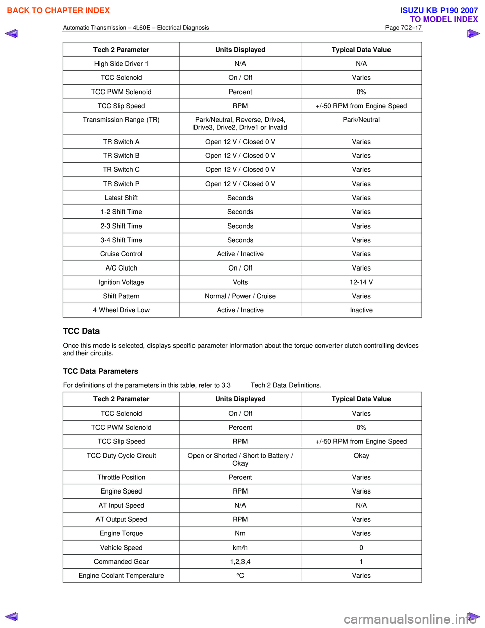
Tech 2 Parameter Units Displayed Typical Data Value
High Side Driver 1 N/A N/A
TCC Solenoid On / Off Varies
TCC PWM Solenoid Percent 0%
TCC Slip Speed RPM +/-50 RPM from Engine Speed
Transmission Range (TR) Park/Neutral, Reverse, Drive4,
Drive3, Drive2, Drive1 or Invalid Park/Neutral
TR Switch A
Open 12 V / Closed 0 V Varies
TR Switch B Open 12 V / Closed 0 V Varies
TR Switch C Open 12 V / Closed 0 V Varies
TR Switch P Open 12 V / Closed 0 V Varies
Latest Shift Seconds Varies
1-2 Shift Time Seconds Varies
2-3 Shift Time Seconds Varies
3-4 Shift Time Seconds Varies
Cruise Control Active / Inactive Varies
A/C Clutch On / Off Varies
Ignition Voltage Volts 12-14 V
Shift Pattern Normal / Power / Cruise Varies
4 Wheel Drive Low Active / Inactive Inactive
TCC Data
Once this mode is selected, displays specific parameter information about the torque converter clutch controlling devices
and their circuits.
TCC Data Parameters
For definitions of the parameters in this table, refer to 3.3 Tech 2 Data Definitions.
Tech 2 Parameter Units Displayed Typical Data Value
TCC Solenoid On / Off Varies
TCC PWM Solenoid Percent 0%
TCC Slip Speed RPM +/-50 RPM from Engine Speed
TCC Duty Cycle Circuit Open or Shorted / Short to Battery /
Okay Okay
Throttle Position
Percent Varies
Engine Speed RPM Varies
AT Input Speed N/A N/A
AT Output Speed RPM Varies
Engine Torque Nm Varies
Vehicle Speed km/h 0
Commanded Gear 1,2,3,4 1
Engine Coolant Temperature °C Varies
BACK TO CHAPTER INDEX
TO MODEL INDEX
ISUZU KB P190 2007