2007 ISUZU KB P190 wiring diagram
[x] Cancel search: wiring diagramPage 3982 of 6020
7A2-16 TRANSMISSION CONTROL SYSTEM (AW30–40LE)
CAN bus systems in automatic
transmission control (AW30-40LE)
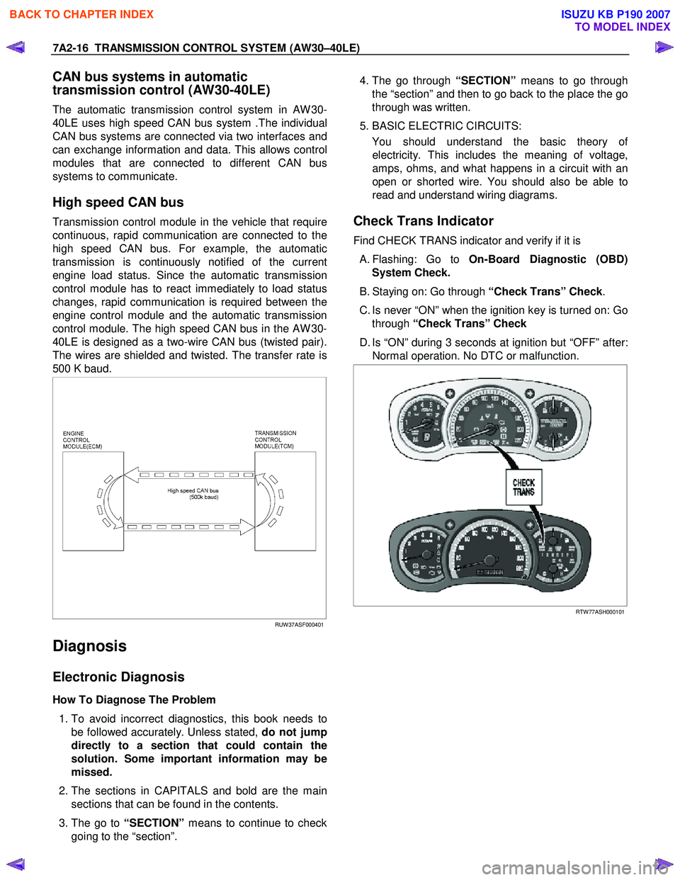
The automatic transmission control system in AW 30-
40LE uses high speed CAN bus system .The individual
CAN bus systems are connected via two interfaces and
can exchange information and data. This allows control
modules that are connected to different CAN bus
systems to communicate.
High speed CAN bus
Transmission control module in the vehicle that require
continuous, rapid communication are connected to the
high speed CAN bus. For example, the automatic
transmission is continuously notified of the current
engine load status. Since the automatic transmission
control module has to react immediately to load status
changes, rapid communication is required between the
engine control module and the automatic transmission
control module. The high speed CAN bus in the AW 30-
40LE is designed as a two-wire CAN bus (twisted pair).
The wires are shielded and twisted. The transfer rate is
500 K baud.
RUW 37ASF000401
Diagnosis
Electronic Diagnosis
How To Diagnose The Problem
1. To avoid incorrect diagnostics, this book needs to
be followed accurately. Unless stated, do not jump
directly to a section that could contain the
solution. Some important information may be
missed.
2. The sections in CAPITALS and bold are the main
sections that can be found in the contents.
3. The go to “SECTION” means to continue to check
going to the “section”.
4. The go through “SECTION” means to go through
the “section” and then to go back to the place the go
through was written.
5. BASIC ELECTRIC CIRCUITS:
You should understand the basic theory o
f
electricity. This includes the meaning of voltage,
amps, ohms, and what happens in a circuit with an
open or shorted wire. You should also be able to
read and understand wiring diagrams.
Check Trans Indicator
Find CHECK TRANS indicator and verify if it is
A. Flashing: Go to On-Board Diagnostic (OBD)
System Check.
B. Staying on: Go through “Check Trans” Check.
C. Is never “ON” when the ignition key is turned on: Go through “Check Trans” Check
D. Is “ON” during 3 seconds at ignition but “OFF” after: Normal operation. No DTC or malfunction.
RTW 77ASH000101
BACK TO CHAPTER INDEX
TO MODEL INDEX
ISUZU KB P190 2007
Page 4885 of 6020
TRANSFER CONTROL SYSTEM 7D1-11
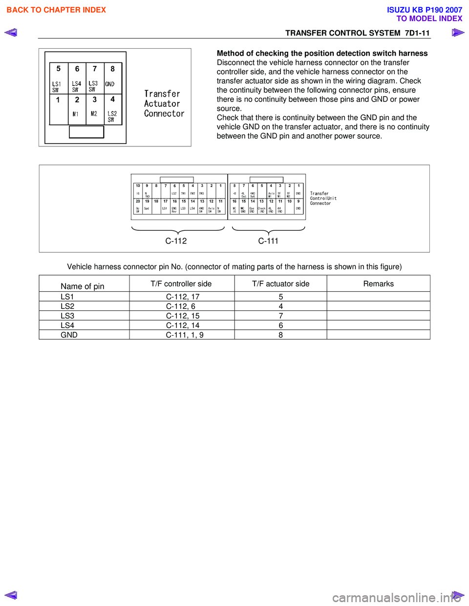
Method of checking the position detection switch harness
Disconnect the vehicle harness connector on the transfer
controller side, and the vehicle harness connector on the
transfer actuator side as shown in the wiring diagram. Check
the continuity between the following connector pins, ensure
there is no continuity between those pins and GND or power
source.
Check that there is continuity between the GND pin and the
vehicle GND on the transfer actuator, and there is no continuity
between the GND pin and another power source.
C-112 C-111
Vehicle harness connector pin No. (connector of mating parts of the harness is shown in this figure)
Name of pin T/F controller side T/F actuator side Remarks
LS1 C-112, 17 5
LS2 C-112, 6 4
LS3 C-112, 15 7
LS4 C-112, 14 6
GND C-111, 1, 9 8
BACK TO CHAPTER INDEX
TO MODEL INDEX
ISUZU KB P190 2007
Page 4939 of 6020
ELECTRICAL-BODY AND CHASSIS 8A-1
SECTION 8A
ELECTRICAL-BODY AND CHASSIS
TABLE OF CONTENTS
PAGE
General Information ........................................................................................................... .........8A- 4
Notes for Working on Electrical Items .......................................................................................8A - 5
Symbols and A bbreviations ..................................................................................................... ..8A- 11
Symbols ....................................................................................................................... ................ 8A- 11
Abbreviations ................................................................................................................. ..............8A- 12
Parts for Electri cal Circuit .................................................................................................. ........8A- 13
Wiring ........................................................................................................................ ...................8A- 13
Fuse .......................................................................................................................... ....................8A- 15
Fusible Link .................................................................................................................. ...............8A- 15
Relay ......................................................................................................................... ....................8A- 16
Diode ......................................................................................................................... ...................8A- 17
Connector ..................................................................................................................... ...............8A- 18
Battery ....................................................................................................................... ...................8A- 19
Reading the Circuit Diagram ................................................................................................... ...8A- 22
Parts Location ................................................................................................................ ..............8A- 22
Circuit Diagram ............................................................................................................... .............8A- 23
Connector List ................................................................................................................ .............8A- 23
Main Data and Specifications .................................................................................................. ...8A- 24
Bulb Specifications ........................................................................................................... ..........8A- 24
Relay and Fuse ................................................................................................................ ............8A- 26
Relay and Fuse Box Location (RHD) .........................................................................................8A- 26
Relay and Fuse Box Location (LHD) ..........................................................................................8A- 27
Relay Location ................................................................................................................ .............8A- 28
Fuse and Slow Blow Fuse Location ...........................................................................................8A- 31
Fuse Location ................................................................................................................. .............8A- 33
Diode Location ................................................................................................................ .............8A- 34
Fuse Block Circuit (C24SE) .................................................................................................... ....8A- 35/36
Fuse Block Circuit (HFV6) ...................................................................................................... .....8A- 37
BACK TO CHAPTER INDEX
TO MODEL INDEX
ISUZU KB P190 2007
Page 4951 of 6020
ELECTRICAL-BODY AND CHASSIS 8A-13
PARTS FOR ELECTRICAL CIRCUIT
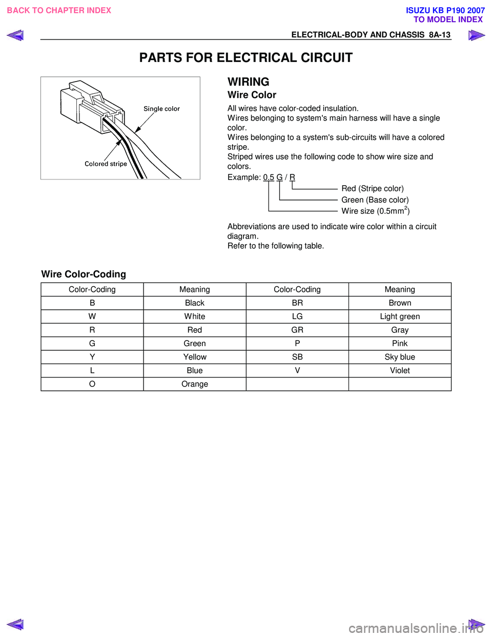
WIRING
Wire Color
All wires have color-coded insulation.
W ires belonging to system's main harness will have a single
color.
W ires belonging to a system's sub-circuits will have a colored
stripe.
Striped wires use the following code to show wire size and
colors.
Example: 0.5 G
/ R
Red (Stripe color)
Green (Base color)
W ire size (0.5mm
2)
Abbreviations are used to indicate wire color within a circuit
diagram.
Refer to the following table.
Wire Color-Coding
Color-Coding Meaning Color-Coding Meaning
B Black BR Brown
W W hite LG Light green
R Red GR Gray
G Green P Pink
Y Yellow SB Sky blue
L Blue V Violet
O Orange
BACK TO CHAPTER INDEX
TO MODEL INDEXISUZU KB P190 2007
Page 4954 of 6020
8A-16 ELECTRICAL-BODY AND CHASSIS
RELAY
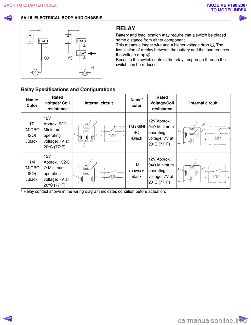
Battery and load location may require that a switch be placed
some distance from either component.
This means a longer wire and a higher voltage drop
1. The
installation of a relay between the battery and the load reduces
the voltage drop
2.
Because the switch controls the relay, amperage through the
switch can be reduced.
Relay Specifications and Configurations
Name/ Color Rated
voltage/ Coil resistance Internal circuit
Name/
color Rated
Voltage/Coil resistance Internal circuit
1T
(MICRO ISO)
/Black 12V
Approx. 92 Ω
Minimum
operating
voltage: 7V at
20 °C (77 °F)
1M (MINI
ISO)
/Black 12V Approx.
94 Ω Minimum
operating
voltage: 7V at
20 °C (77 °F)
1M
(MICRO ISO)
/Black 12V
Approx. 132-3
Ω Minimum
operating
voltage: 7V at
20 °C (77 °F)
1M
(power)/ Black 12V Approx.
94 Ω Minimum
operating
voltage: 7V at
20 °C (77 °F)
* Relay contact shown in the wiring diagram indicates condition before actuation.
BACK TO CHAPTER INDEX TO MODEL INDEXISUZU KB P190 2007
Page 5579 of 6020
Cruise Control – HFV6 Page 8C–1
8C
Cruise Control – HFV6
ATTENTION
Before performing any Service Operation or other procedure described in this Section, refer to General Information Warnings, Cautions and Notes for correct workshop practices with regard to safety and/or property damage.
1 General Information ...............................................................................................................................3
1.1 WARNINGS, CAUTIONS and NOTES................................................................................................... ................. 3
Definition of WARNING, CAUTION and NOTE Statements ............................................................................. .... 3
WARNING Defined............................................................................................................................................. 3
CAUTION Defined .............................................................................................................................................. 3
NOTE Defined .................................................................................................................................................... 4
1.2 System Components .............................................................................................................. ............................... 4
Cruise Control Switch Assembly ................................................................................................. ....................... 5
Instrument Cluster Assembly ............................................................................................................................. 5
Clutch Pedal Switch (Manual Only) .............................................................................................. ...................... 5
Stop Lamp Switch Assembly .............................................................................................................................. 5
Powertrain Interface Module .............................................................................................................................. 6
Engine Control Module ....................................................................................................................................... 6
Throttle Actuator Control (TAC) Assembly ....................................................................................... .................. 6
1.3 System Operation .................................................................................................................................................. 6
Preliminary Information......................................................................................................................................... 6
Enabled and Disabled ........................................................................................................... ............................. 6
Activated and Deactivated...................................................................................................... ............................ 7
Enabling the Cruise Control.................................................................................................... .............................. 7
Brake Before Cruise .............................................................................................................................................. 7
Activating the Cruise Control .................................................................................................. ............................. 7
Deactivating the Cruise Control ................................................................................................ ........................... 7
Pressing the Brake Pedal ................................................................................................................................... 7
Pressing the Cruise ON–OFF Button .............................................................................................. ................... 8
Rotating the Cruise Control Switch Assembly .................................................................................... ................ 8
Pressing the Clutch Pedal (Manual Vehicles Only) ............................................................................... ............. 8
Decelerating While Cruise Control is Activated ................................................................................. ................. 8
Resuming a Speed After Cruise Control Has Been Deactivated ..................................................................... .. 8
Accelerating While Cruise Control is Activated .................................................................................................. 8
Using the Cruise Control Switch Assembly ........................................................................................................ 8
Pressing the Accelerator Pedal .......................................................................................................................... 8
2 Diagnostics .............................................................................................................................................9
2.1 Diagnostic General Information............................................................................................................................ 9
Basic Knowledge Required ................................................................................................................................... 9
Basic Diagnostic Tools Required ......................................................................................................................... 9
Tech 2 Data List ................................................................................................................................................... 10
2.2 Diagnostic Systems Check ....................................................................................................... .......................... 10
Diagnostic Systems Check ................................................................................................................................. 10
2.3 Wiring Diagrams .................................................................................................................................................. 12
2.4 Cruise Control Inoperative / Malfunctioning.................................................................................... .................. 14
Circuit Description ............................................................................................................................................ 14
Manual Vehicles Only........................................................................................................... ............................ 14
Test Description ............................................................................................................................................... 14
Diagnostic Table Notes ......................................................................................................... ........................... 14
Diagnostic Table............................................................................................................................................... 14
SECTION
BACK TO CHAPTER INDEX
TO MODEL INDEX
ISUZU KB P190 2007
Page 5583 of 6020
Cruise Control – HFV6 Page 8C–5
Legend
1 Engine Control Module
2 Throttle Actuator Control (TAC) Assembly
3 Cruise Control Switch Assembly
4 Instrument Cluster Assembly 5 Cruise Control ON / OFF Switch
6 Powertrain Interface Module
7 Clutch Pedal Switch Assembly (Manual Only)
8 Stop Lamp Switch Assembly
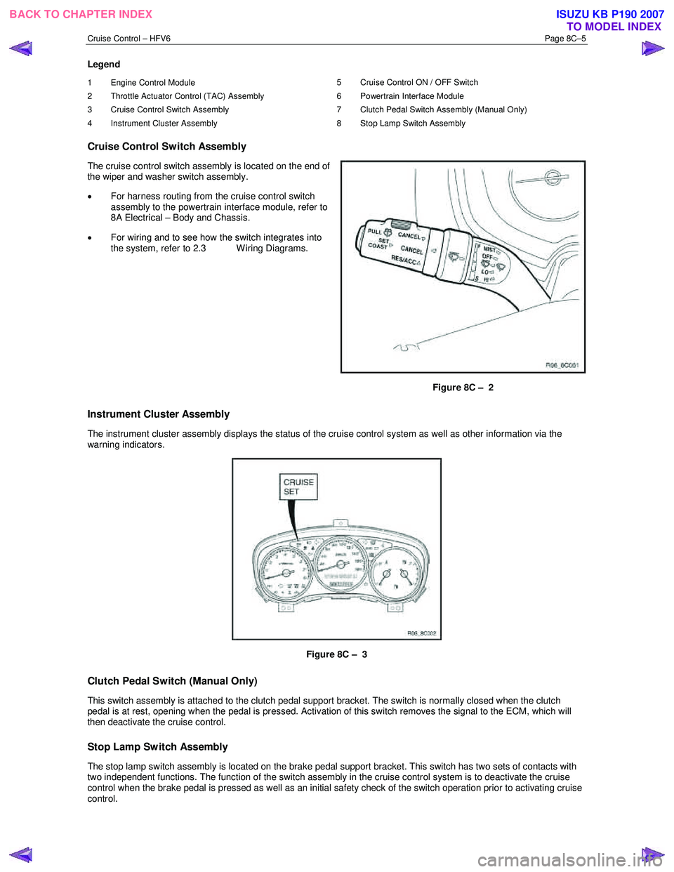
Cruise Control Switch Assembly
The cruise control switch assembly is located on the end of
the wiper and washer switch assembly.
• For harness routing from the cruise control switch
assembly to the powertrain interface module, refer to
8A Electrical – Body and Chassis.
• For wiring and to see how the switch integrates into
the system, refer to 2.3 W iring Diagrams.
Figure 8C – 2
Instrument Cluster Assembly
The instrument cluster assembly displays the status of the cruise control system as well as other information via the
warning indicators.
Figure 8C – 3
Clutch Pedal Switch (Manual Only)
This switch assembly is attached to the clutch pedal support bracket. The switch is normally closed when the clutch
pedal is at rest, opening when the pedal is pressed. Activation of this switch removes the signal to the ECM, which will
then deactivate the cruise control.
Stop Lamp Switch Assembly
The stop lamp switch assembly is located on the brake pedal support bracket. This switch has two sets of contacts with
two independent functions. The function of the switch assembly in the cruise control system is to deactivate the cruise
control when the brake pedal is pressed as well as an initial safety check of the switch operation prior to activating cruise
control.
BACK TO CHAPTER INDEX TO MODEL INDEXISUZU KB P190 2007
Page 5585 of 6020
Cruise Control – HFV6 Page 8C–7
Activated and Deactivated
When the cruise control is enabled, the vehicle speed must be above 40 km/h and the cruise control switch assembly
pressed to SET–COAST, the cruise control will be activated and the vehicle will maintain the set speed. When
deactivated by the methods described within this section, the vehicle will no longer maintain the set speed, but the cruise
control will still be engaged.
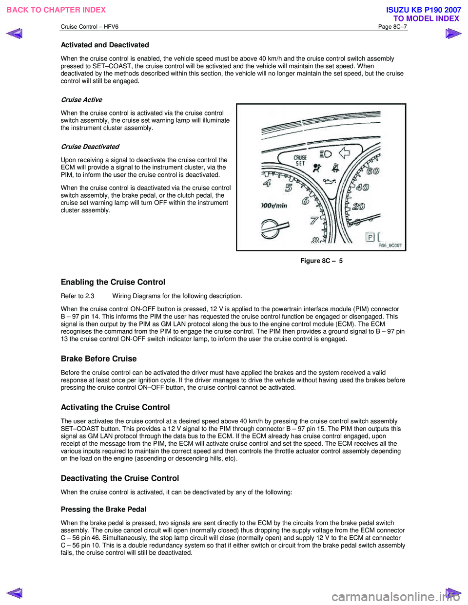
Cruise Active
When the cruise control is activated via the cruise control
switch assembly, the cruise set warning lamp will illuminate
the instrument cluster assembly.
Cruise Deactivated
Upon receiving a signal to deactivate the cruise control the
ECM will provide a signal to the instrument cluster, via the
PIM, to inform the user the cruise control is deactivated.
When the cruise control is deactivated via the cruise control
switch assembly, the brake pedal, or the clutch pedal, the
cruise set warning lamp will turn OFF within the instrument
cluster assembly.
Figure 8C – 5
Enabling the Cruise Control
Refer to 2.3 Wiring Diagrams for the following description.
W hen the cruise control ON-OFF button is pressed, 12 V is applied to the powertrain interface module (PIM) connector
B – 97 pin 14. This informs the PIM the user has requested the cruise control function be engaged or disengaged. This
signal is then output by the PIM as GM LAN protocol along the bus to the engine control module (ECM). The ECM
recognises the command from the PIM to engage the cruise control. The PIM then provides a ground signal to B – 97 pin
13 the cruise control ON-OFF switch indicator lamp, to inform the user the cruise control is engaged.
Brake Before Cruise
Before the cruise control can be activated the driver must have applied the brakes and the system received a valid
response at least once per ignition cycle. If the driver manages to drive the vehicle without having used the brakes before
pressing the cruise control ON–OFF button, the cruise control cannot be activated.
Activating the Cruise Control
The user activates the cruise control at a desired speed above 40 km/h by pressing the cruise control switch assembly
SET–COAST button. This provides a 12 V signal to the PIM through connector B – 97 pin 15. The PIM then outputs this
signal as GM LAN protocol through the data bus to the ECM. If the ECM already has cruise control engaged, upon
receipt of the message from the PIM, the ECM will activate cruise control and set the speed. The ECM receives all the
various inputs required to maintain the correct speed and then controls the throttle actuator control assembly depending
on the load on the engine (ascending or descending hills, etc).
Deactivating the Cruise Control
When the cruise control is activated, it can be deactivated by any of the following:
Pressing the Brake Pedal
When the brake pedal is pressed, two signals are sent directly to the ECM by the circuits from the brake pedal switch
assembly. The cruise cancel circuit will open (normally closed) thus dropping the supply voltage from the ECM connector
C – 56 pin 46. Simultaneously, the stop lamp circuit will close (normally open) and supply 12 V to the ECM at connector
C – 56 pin 10. This is a double redundancy system so that if either switch or circuit from the brake pedal switch assembly
fails, the cruise control will still be deactivated.
BACK TO CHAPTER INDEX TO MODEL INDEXISUZU KB P190 2007