2007 ISUZU KB P190 ECO mode
[x] Cancel search: ECO modePage 4216 of 6020
UNIT REPAIR (AW30–40LE) 7A4–81
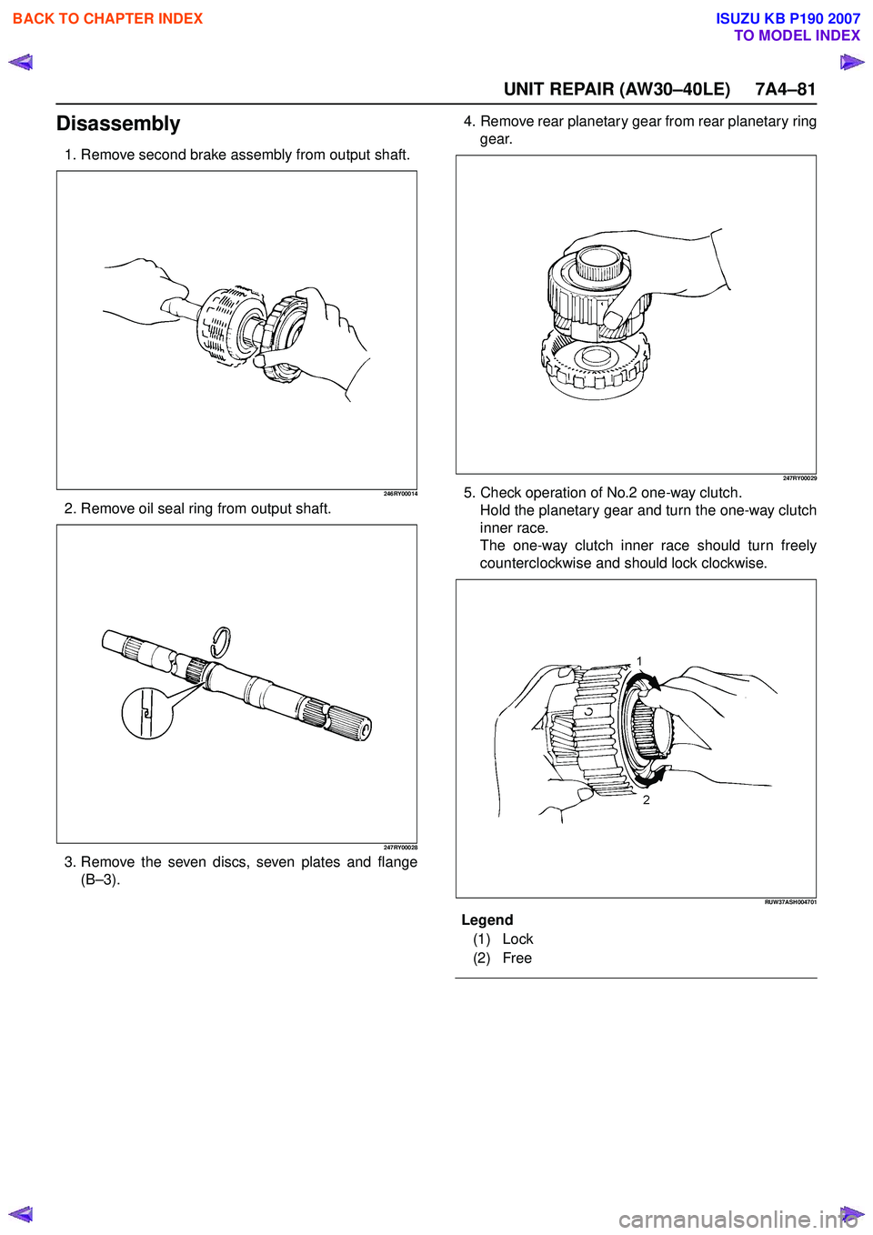
Disassembly
1. Remove second brake assembly from output shaft.
246RY00014
2. Remove oil seal ring from output shaft.
247RY00028
3. Remove the seven discs, seven plates and flange(B–3). 4. Remove rear planetary gear from rear planetary ring
gear.
247RY00029
5. Check operation of No.2 one-way clutch.Hold the planetary gear and turn the one-way clutch
inner race.
The one-way clutch inner race should turn freely
counterclockwise and should lock clockwise.
RUW37ASH004701
En dOFCallout
Legend
(1) Lock
(2) Free
BACK TO CHAPTER INDEX
TO MODEL INDEX
ISUZU KB P190 2007
Page 4220 of 6020
UNIT REPAIR (AW30–40LE) 7A4–85
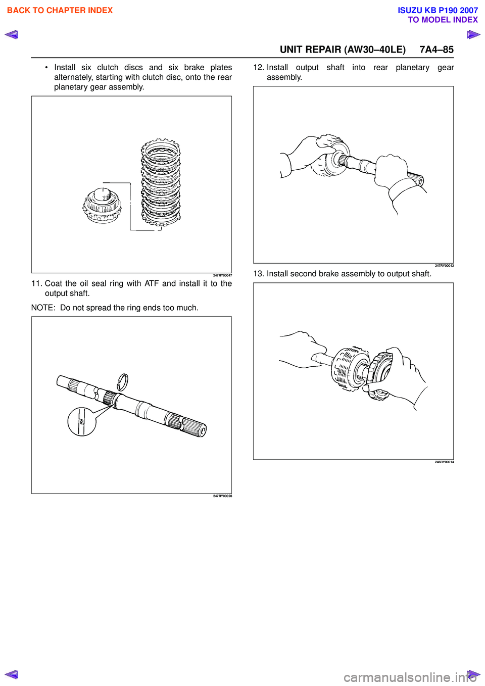
Install six clutch discs and six brake plates
alternately, starting with clutch disc, onto the rear
planetary gear assembly.
247RY00047
11. Coat the oil seal ring with ATF and install it to the output shaft.
NOTE: Do not spread the ring ends too much.
247RY00028
12. Install output shaft into rear planetary gear assembly.
247RY00042
13. Install second brake assembly to output shaft.
246RY00014
BACK TO CHAPTER INDEX
TO MODEL INDEX
ISUZU KB P190 2007
Page 4233 of 6020
7A4–98 UNIT REPAIR (AW30–40LE)
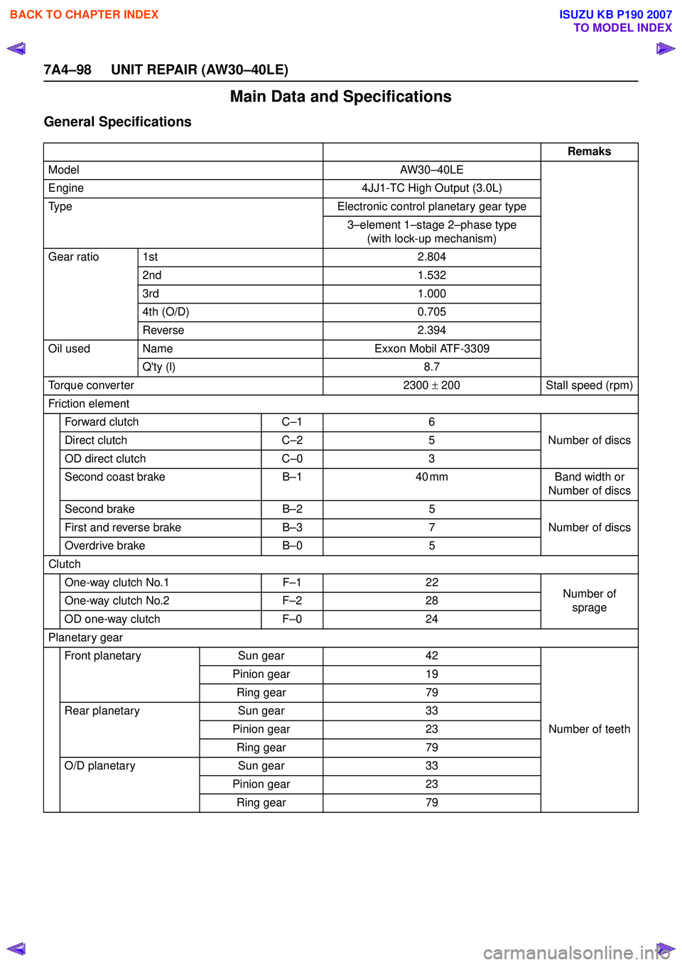
Main Data and Specifications
General Specifications
Remaks
Model AW30–40LE
Engine 4JJ1-TC High Output (3.0L)
Type Electronic control planetary gear type
3–element 1 –stage 2 –phase type
(with lock-up mechanism)
Gear ratio 1st 2.804
2nd 1.532
3rd 1.000
4th (O/D) 0.705
Reverse 2.394
Oil used Name Exxon Mobil ATF-3309
Q'ty (l) 8.7
Torque conver ter 2300 ± 200 Stall speed (rpm)
Friction element Forward clutch C–16
Number of discs
Direct clutch C–25
OD direct clutch C–03
Second coast brake B–1 40 mm Band width or
Number of discs
Second brake B–25
Number of discs
First and reverse brake B–37
Overdrive brake B–05
Clutch One-way clutch No.1 F–12 2
Number of
sprage
One-way clutch No.2
F–22 8
OD one-way clutch F–02 4
Planetary gear Front planetary Sun gear 42
Number of teeth
Pinion gear
19
Ring gear 79
Rear planetary Sun gear 33
Pinion gear 23
Ring gear 79
O/D planetary Sun gear 33
Pinion gear 23
Ring gear 79
BACK TO CHAPTER INDEX
TO MODEL INDEX
ISUZU KB P190 2007
Page 4265 of 6020
7A1-26 CONSTRUCTION AND FUNCTION
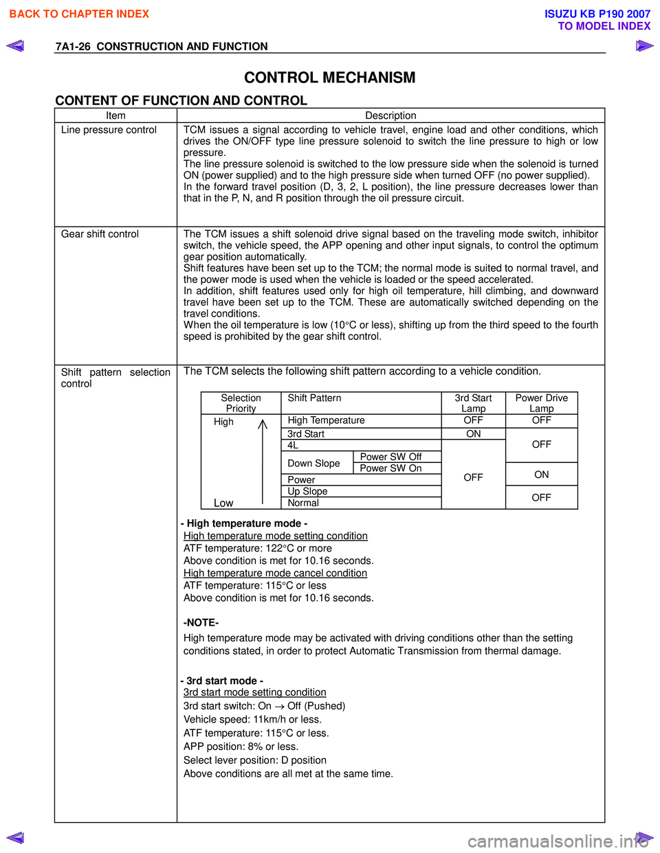
CONTROL MECHANISM
CONTENT OF FUNCTION AND CONTROL
Item Description
Line pressure control TCM issues a signal according to vehicle travel, engine load and other conditions, which
drives the ON/OFF type line pressure solenoid to switch the line pressure to high or low
pressure.
The line pressure solenoid is switched to the low pressure side when the solenoid is turned
ON (power supplied) and to the high pressure side when turned OFF (no power supplied).
In the forward travel position (D, 3, 2, L position), the line pressure decreases lower than
that in the P, N, and R position through the oil pressure circuit.
Gear shift control The TCM issues a shift solenoid drive signal based on the traveling mode switch, inhibitor
switch, the vehicle speed, the APP opening and other input signals, to control the optimum
gear position automatically.
Shift features have been set up to the TCM; the normal mode is suited to normal travel, and
the power mode is used when the vehicle is loaded or the speed accelerated.
In addition, shift features used only for high oil temperature, hill climbing, and downward
travel have been set up to the TCM. These are automatically switched depending on the
travel conditions.
W hen the oil temperature is low (10°C or less), shifting up from the third speed to the fourth
speed is prohibited by the gear shift control.
Shift pattern selection
control
The TCM selects the following shift pattern according to a vehicle condition.
Selection
Priority Shift Pattern 3rd Start
Lamp Power Drive
Lamp
High High Temperature OFF OFF
3rd Start ON
4L
Power SW Off
OFF
Down Slope
Power SW On
Power ON
Up Slope
Low Normal
OFF
OFF
- High temperature mode -
High temperature mode setting condition
ATF temperature: 122 °C or more
Above condition is met for 10.16 seconds.
High temperature mode cancel condition
ATF temperature: 115 °C or less
Above condition is met for 10.16 seconds.
-NOTE-
High temperature mode may be activated with driving conditions other than the setting
conditions stated, in order to protect Automatic Transmission from thermal damage.
- 3rd start mode -
3rd start mode setting condition
3rd start switch: On → Off (Pushed)
Vehicle speed: 11km/h or less.
ATF temperature: 115 °C or less.
APP position: 8% or less.
Select lever position: D position
Above conditions are all met at the same time.
BACK TO CHAPTER INDEX
TO MODEL INDEX
ISUZU KB P190 2007
Page 4266 of 6020
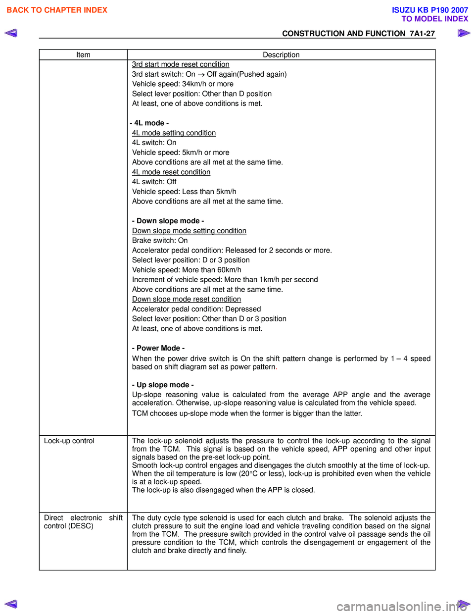
CONSTRUCTION AND FUNCTION 7A1-27
Item Description
3rd start mode reset condition
3rd start switch: On → Off again(Pushed again)
Vehicle speed: 34km/h or more
Select lever position: Other than D position
At least, one of above conditions is met.
- 4L mode -
4L mode setting condition
4L switch: On
Vehicle speed: 5km/h or more
Above conditions are all met at the same time.
4L mode reset condition
4L switch: Off
Vehicle speed: Less than 5km/h
Above conditions are all met at the same time.
- Down slope mode -
Down slope mode setting condition
Brake switch: On
Accelerator pedal condition: Released for 2 seconds or more.
Select lever position: D or 3 position
Vehicle speed: More than 60km/h
Increment of vehicle speed: More than 1km/h per second
Above conditions are all met at the same time.
Down slope mode reset condition
Accelerator pedal condition: Depressed
Select lever position: Other than D or 3 position
At least, one of above conditions is met.
- Power Mode -
W hen the power drive switch is On the shift pattern change is performed by 1 – 4 speed
based on shift diagram set as power pattern .
- Up slope mode -
Up-slope reasoning value is calculated from the average APP angle and the average
acceleration. Otherwise, up-slope reasoning value is calculated from the vehicle speed.
TCM chooses up-slope mode when the former is bigger than the latter.
Lock-up control The lock-up solenoid adjusts the pressure to control the lock-up according to the signal
from the TCM. This signal is based on the vehicle speed, APP opening and other input
signals based on the pre-set lock-up point.
Smooth lock-up control engages and disengages the clutch smoothly at the time of lock-up.
W hen the oil temperature is low (20°C or less), lock-up is prohibited even when the vehicle
is at a lock-up speed.
The lock-up is also disengaged when the APP is closed.
Direct electronic shift
control (DESC)
The duty cycle type solenoid is used for each clutch and brake. The solenoid adjusts the
clutch pressure to suit the engine load and vehicle traveling condition based on the signal
from the TCM. The pressure switch provided in the control valve oil passage sends the oil
pressure condition to the TCM, which controls the disengagement or engagement of the
clutch and brake directly and finely.
BACK TO CHAPTER INDEX
TO MODEL INDEX
ISUZU KB P190 2007
Page 4283 of 6020
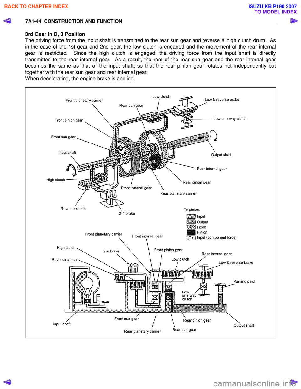
7A1-44 CONSTRUCTION AND FUNCTION
3rd Gear in D, 3 Position
The driving force from the input shaft is transmitted to the rear sun gear and reverse & high clutch drum. As
in the case of the 1st gear and 2nd gear, the low clutch is engaged and the movement of the rear internal
gear is restricted. Since the high clutch is engaged, the driving force from the input shaft is directly
transmitted to the rear internal gear. As a result, the rpm of the rear sun gear and the rear internal gear
becomes the same as that of the input shaft, so that the rear pinion gear rotates not independently but
together with the rear sun gear and rear internal gear.
When decelerating, the engine brake is applied.
BACK TO CHAPTER INDEX
TO MODEL INDEX
ISUZU KB P190 2007
Page 4305 of 6020
TRANSMISSION CONTROL SYSTEM (JR405E) 7A2-21
Diagnostic Information and Procedures
Diagnostic Starting Point - Transmission Controls
Begin the system diagnosis with Diagnostic System
Check - Transmission Controls. The Diagnostic System
Check - Transmission Controls will provide the
following information:
• The identification of the control modules which command the system.
• The ability of the control modules to communicate through the serial data circuit.
• The identification of any stored diagnostic trouble codes (DTCs) and the their statuses.
The use of the Diagnostic System Check -
Transmission Controls will identify the correct
procedure for diagnosing the system and where the
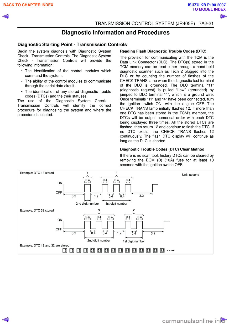
procedure is located. Reading Flash Diagnostic Trouble Codes (DTC)
The provision for communicating with the TCM is the
Data Link Connector (DLC). The DTC(s) stored in the
TCM memory can be read either through a hand-held
diagnostic scanner such as Tech 2 plugged into the
DLC or by counting the number of flashes of the
CHECK TRANS lamp when the diagnostic test terminal
of the DLC is grounded. The DLC terminal “11”
(diagnostic request) is pulled “Low” (grounded) by
jumped to DLC terminal “4”, which is a ground wire.
Once terminals “11” and “4” have been connected, turn
the ignition switch ON, with the engine OFF. The
CHECK TRANS lamp initially flashes 12. If more than
one DTC has been stored in the TCM's memory, the
DTCs will be output numerical order with each DTC
being displayed three times. All the stored DTCs are
flashed, then return 12 and continue to flash the DTC. If
no DTC exists, the CHECK TRANS flashes 12
continuously. The flash DTC display will continue as
long as the DLC is shorted.
Diagnostic Trouble Codes (DTC) Clear Method
If there is no scan tool, history DTCs can be cleared by
removing the ECM (B) (10A) fuse for at least 10
seconds with the ignition switch OFF.
Unit: second
131313323232121313133232321212
Example: DTC 13 stored
ON
OFF
Example: DTC 32 stored
Example: DTC 13 and 32 are stored
ON
OFF 3
1
0.40.40.40.4
32
0.40.40.40.40.4
2nd digit number1st digit number
3.23.20.40.40.41.2
2nd digit number 1st digit number
0.40.41.23.23.2
BACK TO CHAPTER INDEX
TO MODEL INDEX
ISUZU KB P190 2007
Page 4314 of 6020
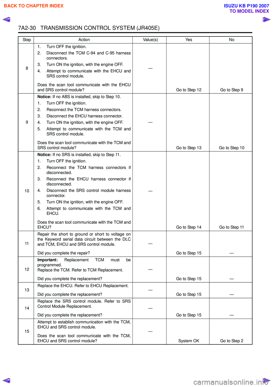
7A2-30 TRANSMISSION CONTROL SYSTEM (JR405E)
81. Turn OFF the ignition.
2. Disconnect the TCM C-94 and C-95 harness connectors.
3. Turn ON the ignition, with the engine OFF.
4. Attempt to communicate with the EHCU and SRS control module.
Does the scan tool communicate with the EHCU
and SRS control module? —
Go to Step 12 Go to Step 9
9 Notice:
If no ABS is installed, skip to Step 10.
1. Turn OFF the ignition.
2. Reconnect the TCM harness connectors.
3. Disconnect the EHCU harness connector.
4. Turn ON the ignition, with the engine OFF.
5. Attempt to communicate with the TCM and SRS control module.
Does the scan tool communicate with the TCM and
SRS control module? —
Go to Step 13 Go to Step 10
10 Notice:
If no SRS is installed, skip to Step 11.
1. Turn OFF the ignition.
2. Reconnect the TCM harness connectors if disconnected.
3. Reconnect the EHCU harness connector if disconnected.
4. Disconnect the SRS control module harness connector.
5. Turn ON the ignition, with the engine OFF.
6. Attempt to communicate with the TCM and EHCU.
Does the scan tool communicate with the TCM and
EHCU? —
Go to Step 14 Go to Step 11
11 Repair the short to ground or short to voltage on
the Keyword serial data circuit between the DLC
and TCM, EHCU and SRS control module.
Did you complete the repair? —
Go to Step 15 —
12 Important:
Replacement TCM must be
programmed.
Replace the TCM. Refer to TCM Replacement.
Did you complete the replacement? —
Go to Step 15 —
13 Replace the EHCU. Refer to EHCU Replacement.
Did you complete the replacement? —
Go to Step 15 —
14 Replace the SRS control module. Refer to SRS
Control Module Replacement.
Did you complete the replacement? —
Go to Step 15 —
15 Attempt to establish communication with the TCM,
EHCU and SRS control module.
Does the scan tool communicate with the TCM,
EHCU and SRS control module? —
System OK Go to Step 2
Step
Action Value(s)Yes No
BACK TO CHAPTER INDEX
TO MODEL INDEX
ISUZU KB P190 2007