2007 ISUZU KB P190 ECO mode
[x] Cancel search: ECO modePage 4085 of 6020
TRANSMISSION CONTROL SYSTEM (AW30–40LE) 7A2-119
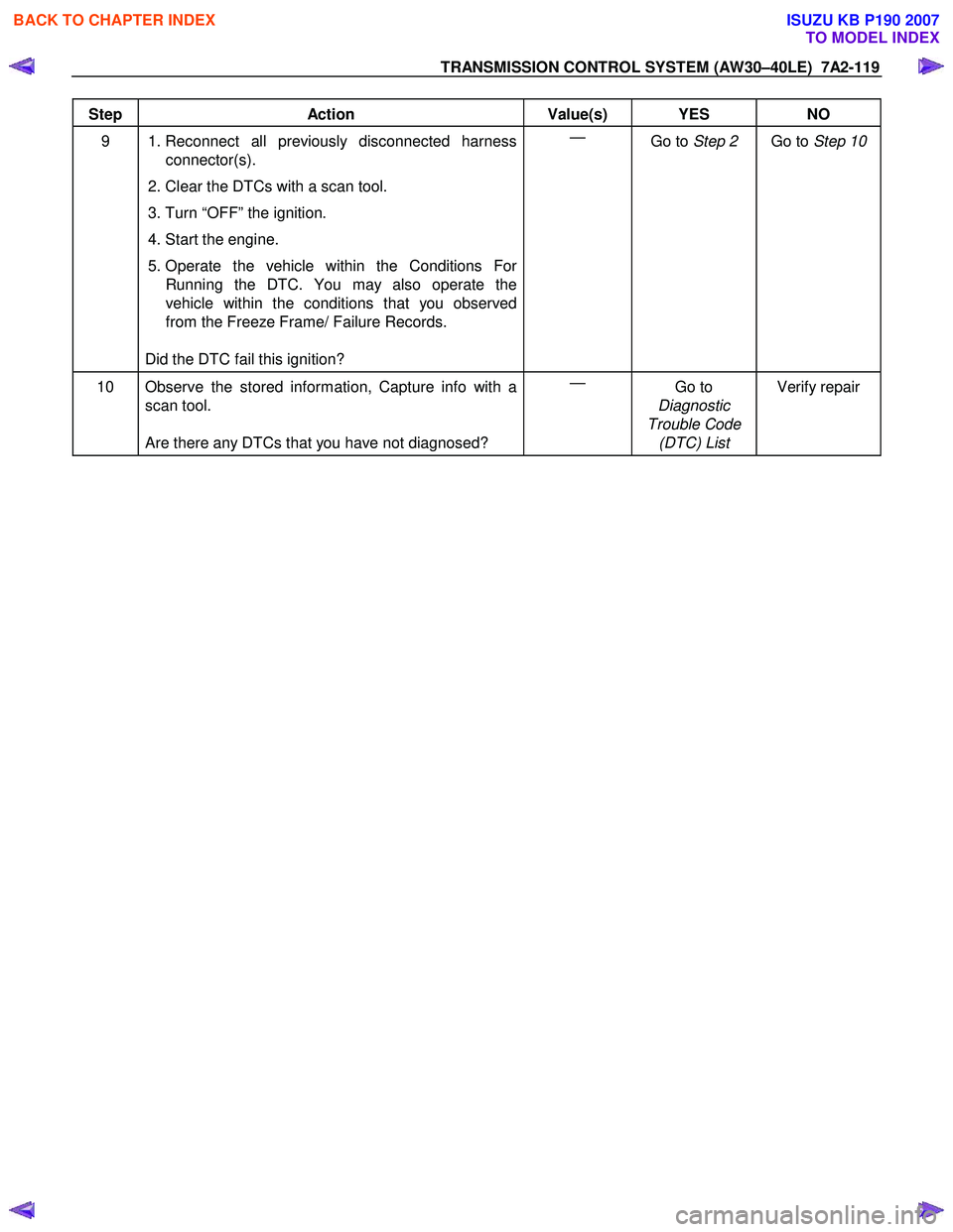
Step Action Value(s) YES NO
9 1. Reconnect all previously disconnected harness
connector(s).
2. Clear the DTCs with a scan tool.
3. Turn “OFF” the ignition.
4. Start the engine.
5. Operate the vehicle within the Conditions For Running the DTC. You may also operate the
vehicle within the conditions that you observed
from the Freeze Frame/ Failure Records.
Did the DTC fail this ignition? —
Go to Step 2 Go to Step 10
10 Observe the stored information, Capture info with a
scan tool.
Are there any DTCs that you have not diagnosed? —
Go to
Diagnostic
Trouble Code (DTC) List Verify repair
BACK TO CHAPTER INDEX
TO MODEL INDEX
ISUZU KB P190 2007
Page 4094 of 6020

ON-VEHICLE SERVICE (AW30–40LE) 7A3-9
Manual Shifting Test
NOTE: W ith this test, it can be determined whether the
trouble lies within the electrical circuit or is a mechanical
problem in the transmission.
1. Disconnect TCM connector
2. Inspect manual driving operation
Check that the relation of the position between
select lever and gear corresponds to the following
table.
If any abnormality is found in the above test, do
perform the stall, time lag or gear shift tests.
RTW 77ASH002901
3. Connect TCM connector
W ith the engine off, connect the TCM connector.
Stall Test
RTW 67ALH000101
The object of this test is to check the overall
performance of the transmission and engine b
y
measuring the maximum engine speeds at the “D" and
“R" positions.
NOTE:
1. Perform the test at normal operating fluid
temperature (50 – 80 °C or 122 – 176 °F).
2. Do not continuously run this test longer than 5 seconds.
BACK TO CHAPTER INDEX
TO MODEL INDEX
ISUZU KB P190 2007
Page 4095 of 6020
7A3-10 ON-VEHICLE SERVICE (AW30–40LE)
Measure Stall Speed
1. Chock the four wheels.
2. Mount an engine tachometer.
3. Fully apply the parking brake.
4. Step down strongly on the brake pedal with your left foot. (Keep the state until the test is completed)
5. Start the engine.
6. Turn off the A/C.
7. Select into the “D" position. Step all the way down on the accelerator pedal with your right foot. Quickl
y
record the highest speed as soon as the engine
speed gets stabilized.
8. Select into the “N” position and maintain the engine
idling condition more than 1 minute.
Stall speed: 2300 ±
±±
±
200 rpm *
* Ambient temperature to be between roughly 10 °C
(50 °F) and 40 °C (104 °F).
Evaluation
1. If the engine speed is the same for both positions
but lower than the specified value:
• Engine output is insufficient.
• Stator one-way clutch is not operating properly.
NOTE: If more than 600 rpm below the specified value,
the torque converter could be faulty.
2. If the stall speed in “D" position is higher than
specified:
• Line pressure too low
• Forward clutch slipping
• No.2 one-way clutch not operating properly
3. If the stall speed in “R" position is higher than
specified:
• Line pressure too low
• Direct clutch slipping
• No.3 brake slipping
4. If the stall speed in the “R" and “D" positions are
higher than specified:
• Line pressure too low
• Improper fluid level
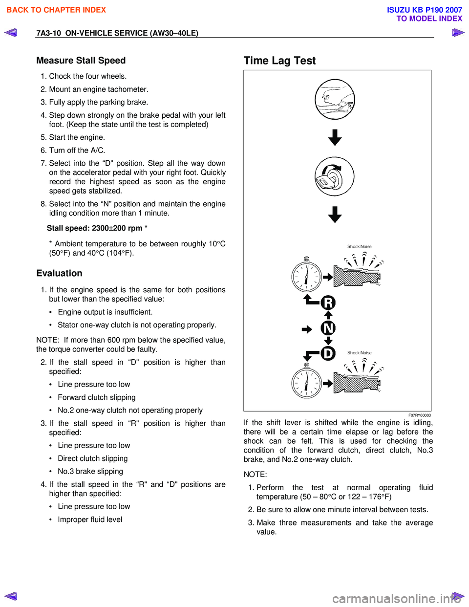
Time Lag Test
F07RY00003
If the shift lever is shifted while the engine is idling,
there will be a certain time elapse or lag before the
shock can be felt. This is used for checking the
condition of the forward clutch, direct clutch, No.3
brake, and No.2 one-way clutch.
NOTE:
1. Perform the test at normal operating fluid
temperature (50 – 80 °C or 122 – 176 °F)
2. Be sure to allow one minute interval between tests.
3. Make three measurements and take the average value.
BACK TO CHAPTER INDEX
TO MODEL INDEX
ISUZU KB P190 2007
Page 4096 of 6020
ON-VEHICLE SERVICE (AW30–40LE) 7A3-11
Measure Time Lag
1. Fully apply the parking brake.
2. Start the engine. Check idling speed (A/C OFF).
3. Operate the select lever from “N" to “D" position.
Using a stopwatch, measure the time it takes from
shifting the lever until the shock is felt.
Time lag: Less than 0.7 seconds
4. In same manner, measure the time lag for “N" →
“R".
Time lag: Less than 1.2 seconds
Evaluation
1. If “N" → “D" time lag is longer than specified:
• Line pressure too low
• Forward clutch malfunction
• No.2 one-way clutch not operating properly
2. If “N" → “R" time lag is longer than specified:
• Line pressure too low
• Direct clutch malfunction
• First and Reverse brake malfunction
3. If both time lag is longer than specified:
• Line pressure too low
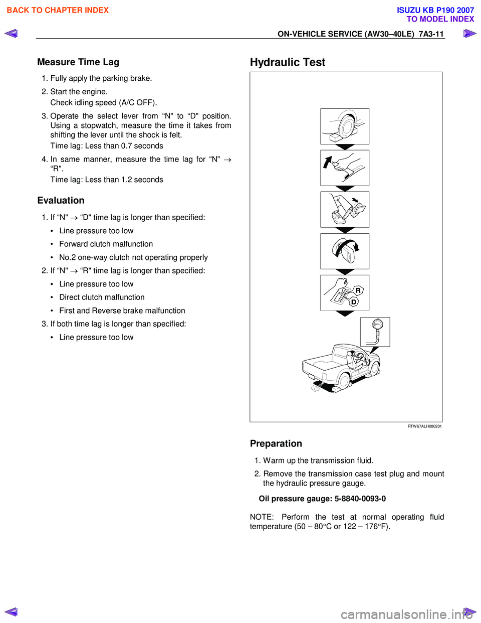
Hydraulic Test
RTW 67ALH000201
Preparation
1. W arm up the transmission fluid.
2. Remove the transmission case test plug and mount the hydraulic pressure gauge.
Oil pressure gauge: 5-8840-0093-0
NOTE: Perform the test at normal operating fluid
temperature (50 – 80 °C or 122 – 176 °F).
BACK TO CHAPTER INDEX
TO MODEL INDEX
ISUZU KB P190 2007
Page 4099 of 6020
7A3-14 ON-VEHICLE SERVICE (AW30–40LE)
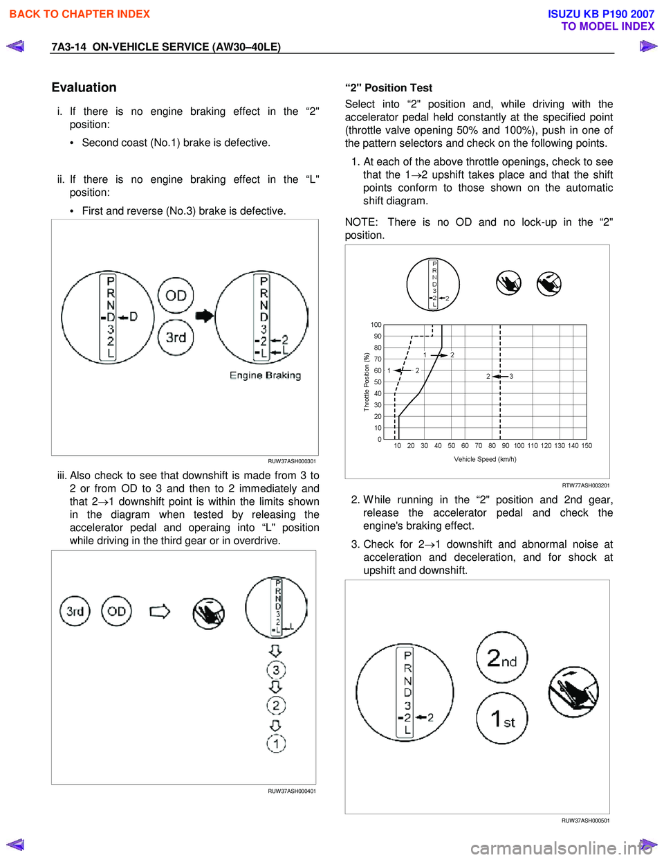
Evaluation
i. If there is no engine braking effect in the “2"
position:
• Second coast (No.1) brake is defective.
ii. If there is no engine braking effect in the “L" position:
• First and reverse (No.3) brake is defective.
RUW 37ASH000301
iii. Also check to see that downshift is made from 3 to
2 or from OD to 3 and then to 2 immediately and
that 2 →1 downshift point is within the limits shown
in the diagram when tested by releasing the
accelerator pedal and operaing into “L" position
while driving in the third gear or in overdrive.
RUW 37ASH000401
“2" Position Test
Select into “2" position and, while driving with the
accelerator pedal held constantly at the specified point
(throttle valve opening 50% and 100%), push in one o
f
the pattern selectors and check on the following points.
1.
At each of the above throttle openings, check to see
that the 1 →2 upshift takes place and that the shift
points conform to those shown on the automatic
shift diagram.
NOTE: There is no OD and no lock-up in the “2"
position.
RTW 77ASH003201
2. W hile running in the “2" position and 2nd gear,
release the accelerator pedal and check the
engine's braking effect.
3. Check for 2 →1 downshift and abnormal noise at
acceleration and deceleration, and for shock at
upshift and downshift.
RUW 37ASH000501
BACK TO CHAPTER INDEX
TO MODEL INDEX
ISUZU KB P190 2007
Page 4136 of 6020
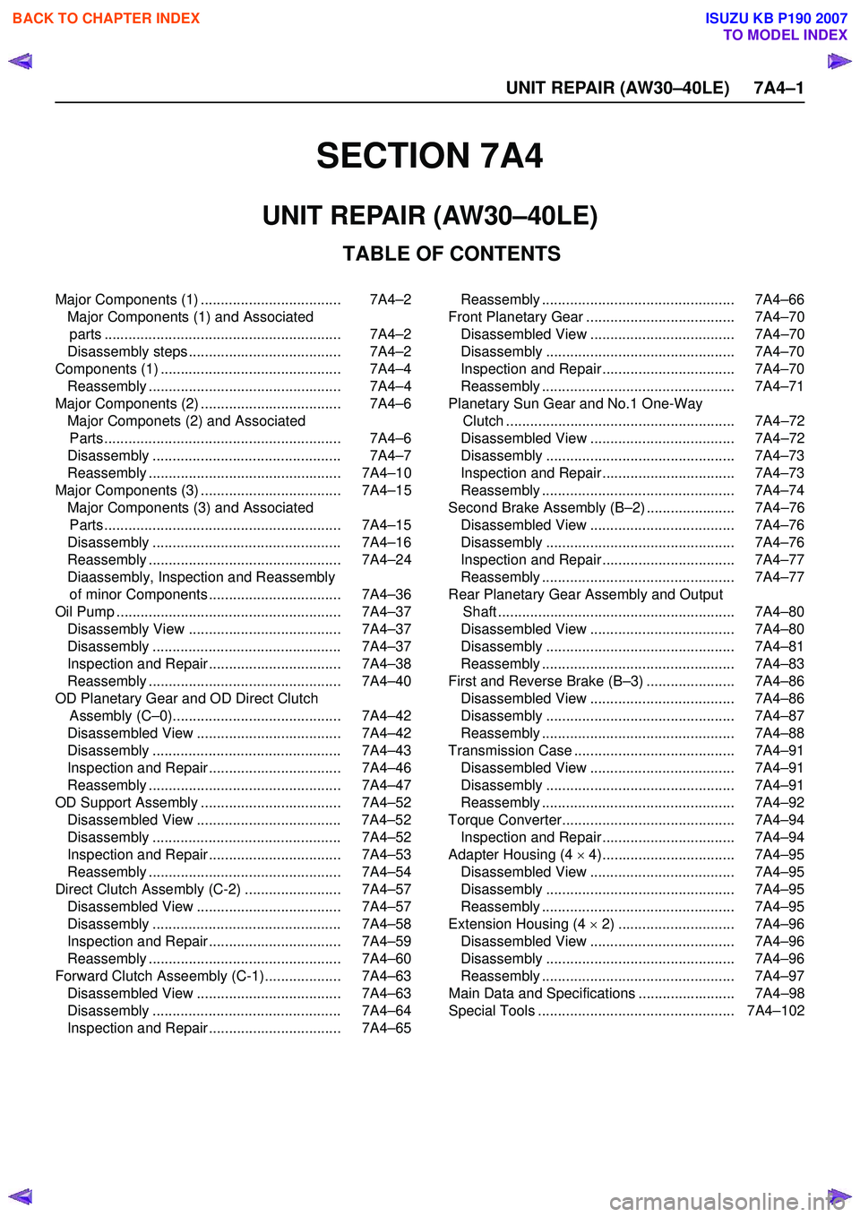
UNIT REPAIR (AW30–40LE) 7A4–1
SECTION 7A4
TABLE OF CONTENTS
UNIT REPAIR (AW30–40LE)
Major Components (1) ................................... 7A4–2Major Components (1) and Associatedparts ........................................................... 7A4–2
Disassembly steps ...................................... 7A4–2
Components (1) ............................................. 7A4–4 Reassembly ................................................ 7A4–4
Major Components (2) ................................... 7A4–6 Major Componets (2) and Associated Parts ........................................................... 7A4–6
Disassembly ............................................... 7A4–7
Reassembly ................................................ 7A4–10
Major Components (3) ................................... 7A4–15 Major Components (3) and AssociatedParts ........................................................... 7A4–15
Disassembly ............................................... 7A4–16
Reassembly ................................................ 7A4–24
Diaassembly, Inspection and Reassembly of minor Components ................................. 7A4–36
Oil Pump ........................................................ 7A4–37 Disassembly View ...................................... 7A4–37
Disassembly ............................................... 7A4–37
Inspection and Repair ................................. 7A4–38
Reassembly ................................................ 7A4–40
OD Planetary Gear and OD Direct Clutch Assembly (C–0).......................................... 7A4–42
Disassembled View .................................... 7A4–42
Disassembly ............................................... 7A4–43
Inspection and Repair ................................. 7A4–46
Reassembly ................................................ 7A4–47
OD Support Assembly ................................... 7A4–52 Disassembled View .................................... 7A4–52
Disassembly ............................................... 7A4–52
Inspection and Repair ................................. 7A4–53
Reassembly ................................................ 7A4–54
Direct Clutch Assembly (C-2) ........................ 7A4–57 Disassembled View .................................... 7A4–57
Disassembly ............................................... 7A4–58
Inspection and Repair ................................. 7A4–59
Reassembly ................................................ 7A4–60
Forward Clutch Asseembly (C-1)................... 7A4–63 Disassembled View .................................... 7A4–63
Disassembly ............................................... 7A4–64
Inspection and Repair ................................. 7A4–65 Reassembly ................................................ 7A4–66
Front Planetary Gear ..................................... 7A4–70 Disassembled View .................................... 7A4–70
Disassembly ............................................... 7A4–70
Inspection and Repair ................................. 7A4–70
Reassembly ................................................ 7A4–71
Planetary Sun Gear and No.1 One-Way Clutch ......................................................... 7A4–72
Disassembled View .................................... 7A4–72
Disassembly ............................................... 7A4–73
Inspection and Repair ................................. 7A4–73
Reassembly ................................................ 7A4–74
Second Brake Assembly (B–2) ...................... 7A4–76 Disassembled View .................................... 7A4–76
Disassembly ............................................... 7A4–76
Inspection and Repair ................................. 7A4–77
Reassembly ................................................ 7A4–77
Rear Planetary Gear Assembly and Output Shaft ........................................................... 7A4–80
Disassembled View .................................... 7A4–80
Disassembly ............................................... 7A4–81
Reassembly ................................................ 7A4–83
First and Reverse Brake (B–3) ...................... 7A4–86 Disassembled View .................................... 7A4–86
Disassembly ............................................... 7A4–87
Reassembly ................................................ 7A4–88
Transmission Case ........................................ 7A4–91 Disassembled View .................................... 7A4–91
Disassembly ............................................... 7A4–91
Reassembly ................................................ 7A4–92
Torque Converter........................................... 7A4–94 Inspection and Repair ................................. 7A4–94
Adapter Housing (4 × 4)................................. 7A4–95
Disassembled View .................................... 7A4–95
Disassembly ............................................... 7A4–95
Reassembly ................................................ 7A4–95
Extension Housing (4 × 2) ............................. 7A4–96
Disassembled View .................................... 7A4–96
Disassembly ............................................... 7A4–96
Reassembly ................................................ 7A4–97
Main Data and Specifications ........................ 7A4–98
Special Tools ................................................. 7A4–102
BACK TO CHAPTER INDEX
TO MODEL INDEX
ISUZU KB P190 2007
Page 4144 of 6020
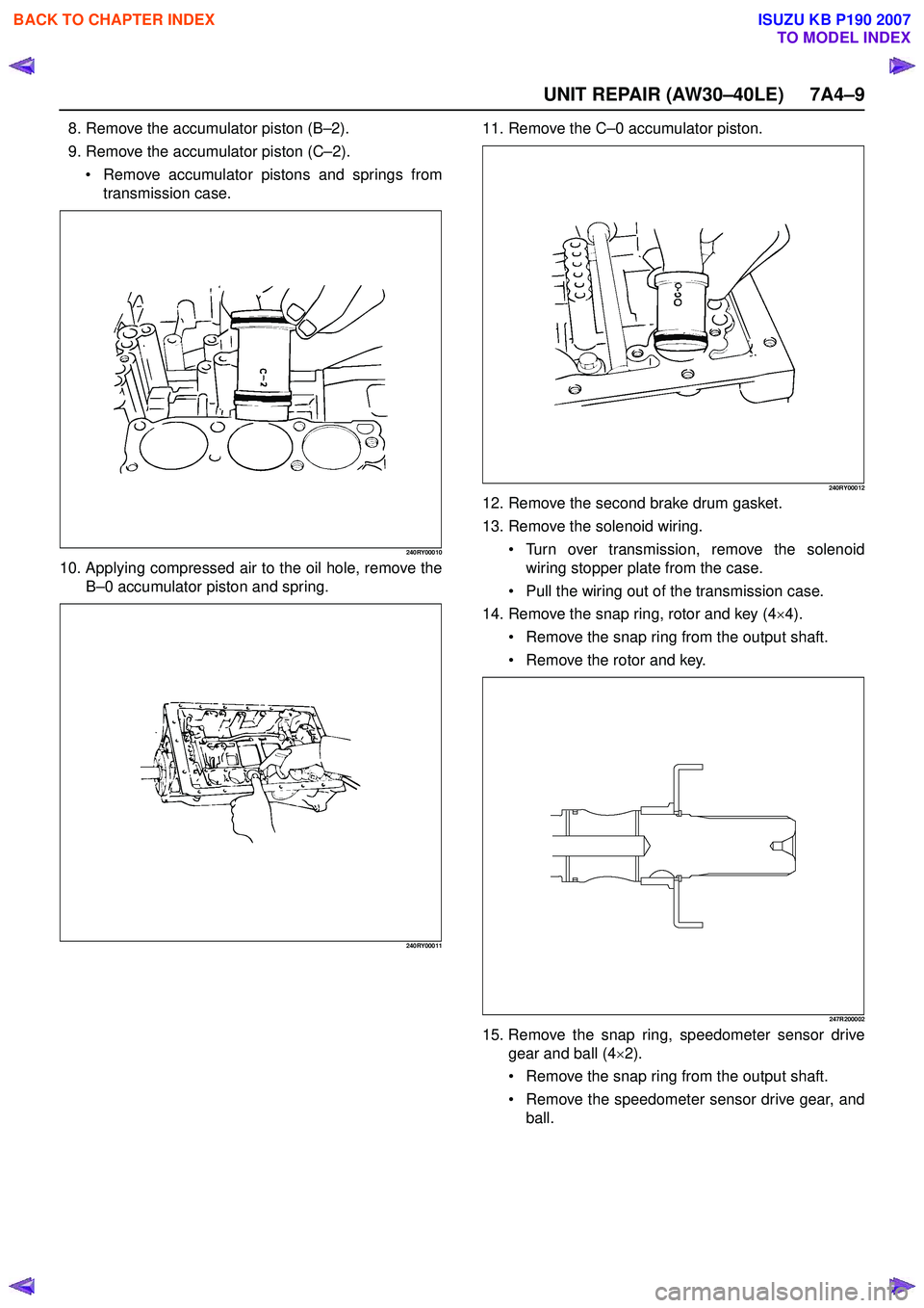
UNIT REPAIR (AW30–40LE) 7A4–9
8. Remove the accumulator piston (B–2).
9. Remove the accumulator piston (C –2).
Remove accumulator pistons and springs from
transmission case.
240RY00010
10. Applying compressed air to the oil hole, remove the B–0 accumulator piston and spring.
240RY00011
11. Remove the C –0 accumulator piston.
240RY00012
12. Remove the second brake drum gasket.
13. Remove the solenoid wiring.
Turn over transmission, remove the solenoid
wiring stopper plate from the case.
Pull the wiring out of the transmission case.
14. Remove the snap ring, rotor and key (4 ×4).
Remove the snap ring from the output shaft.
Remove the rotor and key.
247R200002
15. Remove the snap ring, speedometer sensor drive
gear and ball (4 ×2).
Remove the snap ring from the output shaft.
Remove the speedometer sensor drive gear, and
ball.
BACK TO CHAPTER INDEX
TO MODEL INDEX
ISUZU KB P190 2007
Page 4146 of 6020
UNIT REPAIR (AW30–40LE) 7A4–11
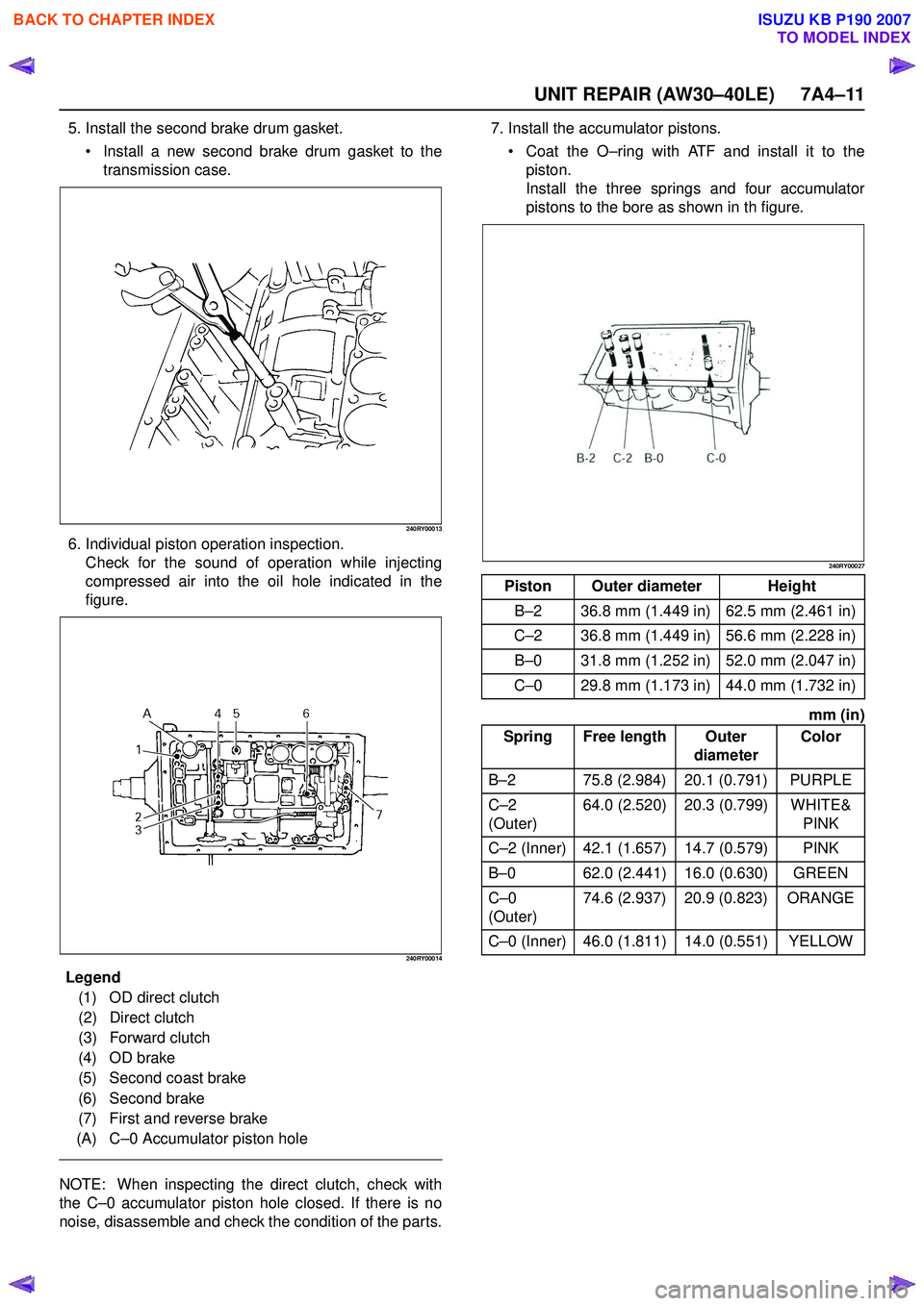
5. Install the second brake drum gasket. Install a new second brake drum gasket to the
transmission case.
240RY00013
6. Individual piston operation inspection. Check for the sound of operation while injecting
compressed air into the oil hole indicated in the
figure.
240RY00014
E ndOFCallout
NOTE: When inspecting the direct clutch, check with
the C –0 accumulator piston hole closed. If there is no
noise, disassemble and check the condition of the parts. 7. Install the accumulator pistons.
Coat the O –ring with ATF and install it to the
piston.
Install the three springs and four accumulator
pistons to the bore as shown in th figure.
240RY00027
mm (in)
Legend (1) OD direct clutch
(2) Direct clutch
(3) Forward clutch
(4) OD brake
(5) Second coast brake
(6) Second brake
(7) First and reverse brake
(A) C –0 Accumulator piston hole
Piston Outer diameter Height
B –2 36.8 mm (1.449 in) 62.5 mm (2.461 in)
C –2 36.8 mm (1.449 in) 56.6 mm (2.228 in)
B –0 31.8 mm (1.252 in) 52.0 mm (2.047 in)
C –0 29.8 mm (1.173 in) 44.0 mm (1.732 in)
Spring Free length Outer diameterColor
B –2 75.8 (2.984) 20.1 (0.791) PURPLE
C –2
(Outer) 64.0 (2.520) 20.3 (0.799) WHITE&
PINK
C –2 (Inner) 42.1 (1.657) 14.7 (0.579) PINK
B –0 62.0 (2.441) 16.0 (0.630) GREEN
C –0
(Outer) 74.6 (2.937) 20.9 (0.823) ORANGE
C –0 (Inner) 46.0 (1.811) 14.0 (0.551) YELLOW
BACK TO CHAPTER INDEX
TO MODEL INDEX
ISUZU KB P190 2007