2007 ISUZU KB P190 FLASH CODE
[x] Cancel search: FLASH CODEPage 1258 of 6020
6E-224 Engine Control System (4JH1)
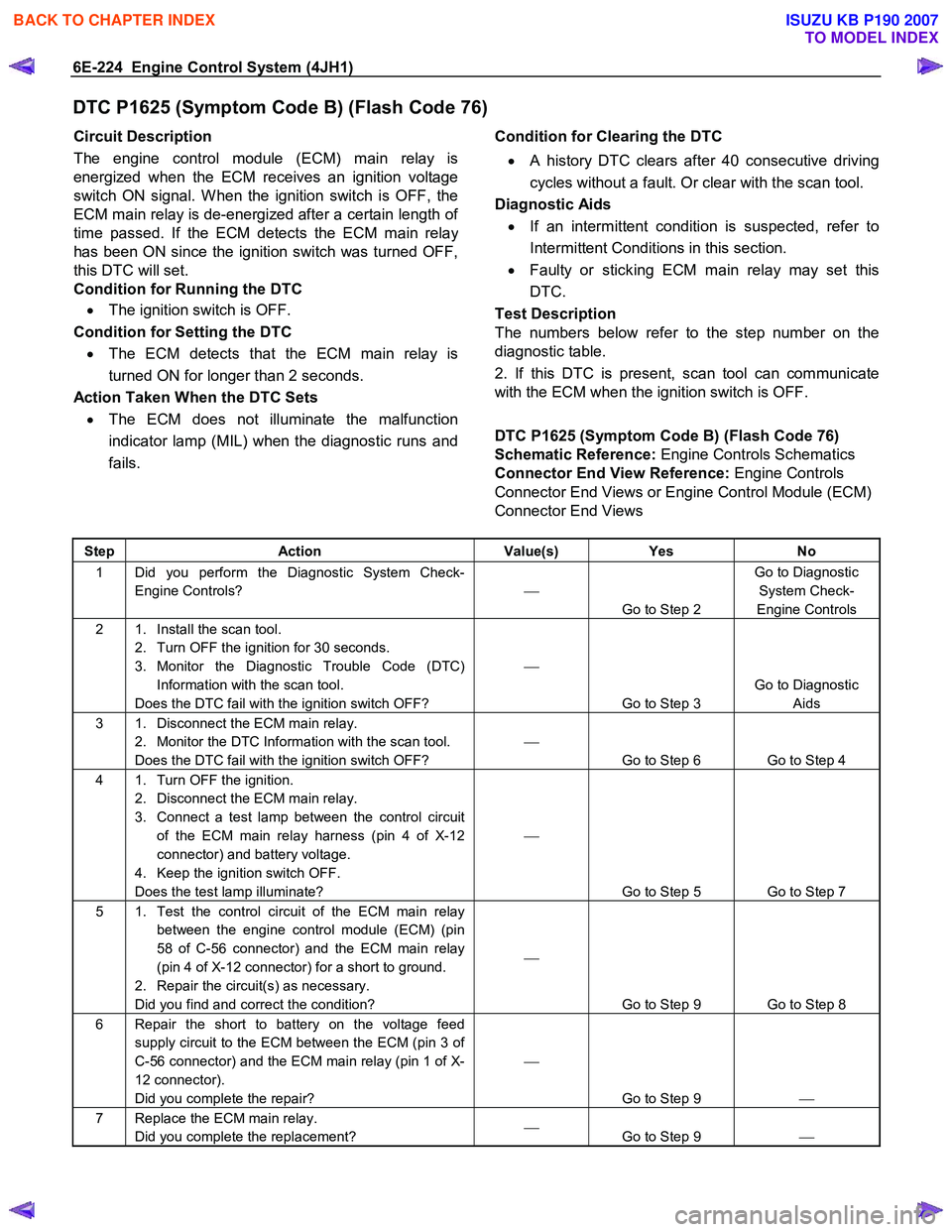
DTC P1625 (Symptom Code B) (Flash Code 76)
Circuit Description
The engine control module (ECM) main relay is
energized when the ECM receives an ignition voltage
switch ON signal. W hen the ignition switch is OFF, the
ECM main relay is de-energized after a certain length o
f
time passed. If the ECM detects the ECM main relay
has been ON since the ignition switch was turned OFF,
this DTC will set.
Condition for Running the DTC
• The ignition switch is OFF.
Condition for Setting the DTC • The ECM detects that the ECM main relay is
turned ON for longer than 2 seconds.
Action Taken When the DTC Sets • The ECM does not illuminate the malfunction
indicator lamp (MIL) when the diagnostic runs and
fails.
Condition for Clearing the DTC
• A history DTC clears after 40 consecutive driving
cycles without a fault. Or clear with the scan tool.
Diagnostic Aids
• If an intermittent condition is suspected, refer to
Intermittent Conditions in this section.
• Faulty or sticking ECM main relay may set this
DTC.
Test Description
The numbers below refer to the step number on the
diagnostic table.
2. If this DTC is present, scan tool can communicate
with the ECM when the ignition switch is OFF.
DTC P1625 (Symptom Code B) (Flash Code 76)
Schematic Reference: Engine Controls Schematics
Connector End View Reference: Engine Controls
Connector End Views or Engine Control Module (ECM)
Connector End Views
Step Action Value(s) Yes No
1 Did you perform the Diagnostic System Check-
Engine Controls?
Go to Step 2 Go to Diagnostic
System Check-
Engine Controls
2 1. Install the scan tool. 2. Turn OFF the ignition for 30 seconds.
3. Monitor the Diagnostic Trouble Code (DTC) Information with the scan tool.
Does the DTC fail with the ignition switch OFF?
Go to Step 3 Go to Diagnostic
Aids
3 1. Disconnect the ECM main relay. 2. Monitor the DTC Information with the scan tool.
Does the DTC fail with the ignition switch OFF?
Go to Step 6 Go to Step 4
4 1. Turn OFF the ignition. 2. Disconnect the ECM main relay.
3. Connect a test lamp between the control circuit of the ECM main relay harness (pin 4 of X-12
connector) and battery voltage.
4. Keep the ignition switch OFF.
Does the test lamp illuminate?
Go to Step 5 Go to Step 7
5 1. Test the control circuit of the ECM main relay between the engine control module (ECM) (pin
58 of C-56 connector) and the ECM main relay
(pin 4 of X-12 connector) for a short to ground.
2. Repair the circuit(s) as necessary.
Did you find and correct the condition?
Go to Step 9 Go to Step 8
6 Repair the short to battery on the voltage feed supply circuit to the ECM between the ECM (pin 3 of
C-56 connector) and the ECM main relay (pin 1 of X-
12 connector).
Did you complete the repair?
Go to Step 9
7 Replace the ECM main relay.
Did you complete the replacement?
Go to Step 9
BACK TO CHAPTER INDEX
TO MODEL INDEX
ISUZU KB P190 2007
Page 1260 of 6020
6E-226 Engine Control System (4JH1)
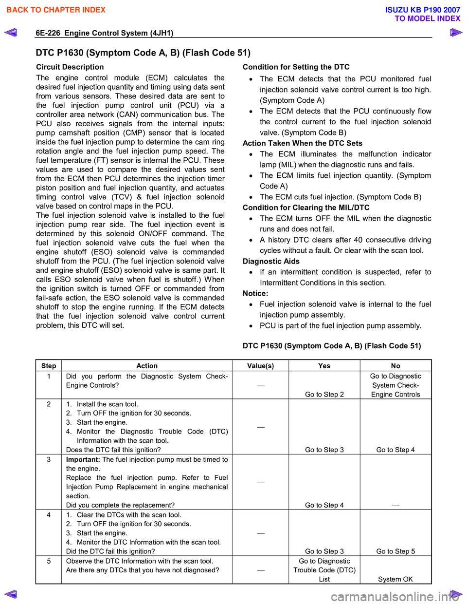
DTC P1630 (Symptom Code A, B) (Flash Code 51)
Circuit Description
The engine control module (ECM) calculates the
desired fuel injection quantity and timing using data sent
from various sensors. These desired data are sent to
the fuel injection pump control unit (PCU) via a
controller area network (CAN) communication bus. The
PCU also receives signals from the internal inputs:
pump camshaft position (CMP) sensor that is located
inside the fuel injection pump to determine the cam ring
rotation angle and the fuel injection pump speed. The
fuel temperature (FT) sensor is internal the PCU. These
values are used to compare the desired values sent
from the ECM then PCU determines the injection time
r
piston position and fuel injection quantity, and actuates
timing control valve (TCV) & fuel injection solenoid
valve based on control maps in the PCU.
The fuel injection solenoid valve is installed to the fuel
injection pump rear side. The fuel injection event is
determined by this solenoid ON/OFF command. The
fuel injection solenoid valve cuts the fuel when the
engine shutoff (ESO) solenoid valve is commanded
shutoff from the PCU. (The fuel injection solenoid valve
and engine shutoff (ESO) solenoid valve is same part. It
calls ESO solenoid valve when fuel is shutoff.) W hen
the ignition switch is turned OFF or commanded from
fail-safe action, the ESO solenoid valve is commanded
shutoff to stop the engine running. If the ECM detects
that the fuel injection solenoid valve control current
problem, this DTC will set.
Condition for Setting the DTC
• The ECM detects that the PCU monitored fuel
injection solenoid valve control current is too high.
(Symptom Code A)
• The ECM detects that the PCU continuously flo
w
the control current to the fuel injection solenoid
valve. (Symptom Code B)
Action Taken When the DTC Sets • The ECM illuminates the malfunction indicato
r
lamp (MIL) when the diagnostic runs and fails.
• The ECM limits fuel injection quantity. (Symptom
Code A)
• The ECM cuts fuel injection. (Symptom Code B)
Condition for Clearing the MIL/DTC • The ECM turns OFF the MIL when the diagnostic
runs and does not fail.
• A history DTC clears after 40 consecutive driving
cycles without a fault. Or clear with the scan tool.
Diagnostic Aids
• If an intermittent condition is suspected, refer to
Intermittent Conditions in this section.
Notice:
• Fuel injection solenoid valve is internal to the fuel
injection pump assembly.
• PCU is part of the fuel injection pump assembly.
DTC P1630 (Symptom Code A, B) (Flash Code 51)
Step Action Value(s) Yes No
1 Did you perform the Diagnostic System Check-
Engine Controls?
Go to Step 2 Go to Diagnostic
System Check-
Engine Controls
2 1. Install the scan tool. 2. Turn OFF the ignition for 30 seconds.
3. Start the engine.
4. Monitor the Diagnostic Trouble Code (DTC) Information with the scan tool.
Does the DTC fail this ignition?
Go to Step 3 Go to Step 4
3 Important: The fuel injection pump must be timed to
the engine.
Replace the fuel injection pump. Refer to Fuel
Injection Pump Replacement in engine mechanical
section.
Did you complete the replacement?
Go to Step 4
4 1. Clear the DTCs with the scan tool.
2. Turn OFF the ignition for 30 seconds.
3. Start the engine.
4. Monitor the DTC Information with the scan tool.
Did the DTC fail this ignition?
Go to Step 3 Go to Step 5
5 Observe the DTC Information with the scan tool. Are there any DTCs that you have not diagnosed? Go to Diagnostic
Trouble Code (DTC) List System OK
BACK TO CHAPTER INDEX
TO MODEL INDEX
ISUZU KB P190 2007
Page 1261 of 6020
Engine Control System (4JH1) 6E-227
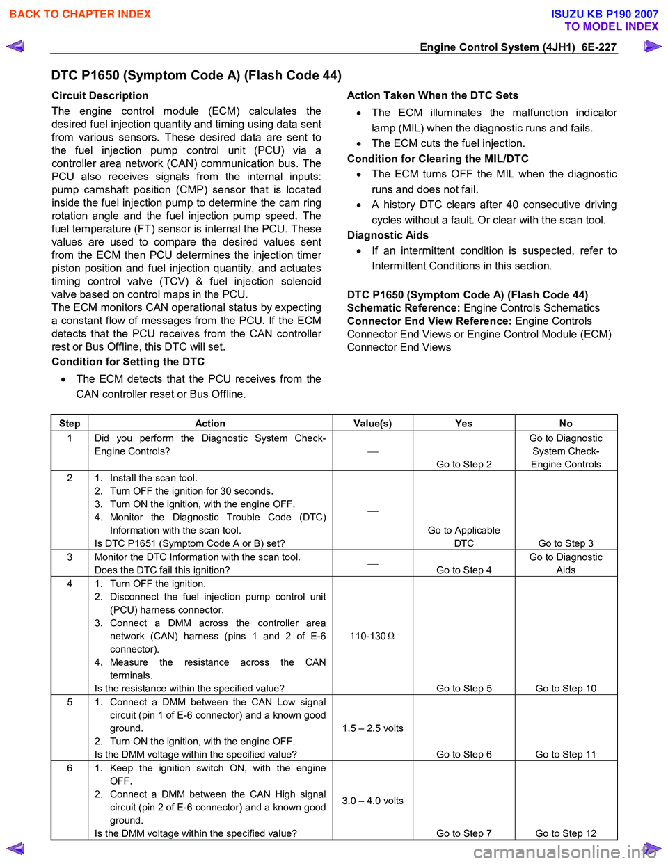
DTC P1650 (Symptom Code A) (Flash Code 44)
Circuit Description
The engine control module (ECM) calculates the
desired fuel injection quantity and timing using data sent
from various sensors. These desired data are sent to
the fuel injection pump control unit (PCU) via a
controller area network (CAN) communication bus. The
PCU also receives signals from the internal inputs:
pump camshaft position (CMP) sensor that is located
inside the fuel injection pump to determine the cam ring
rotation angle and the fuel injection pump speed. The
fuel temperature (FT) sensor is internal the PCU. These
values are used to compare the desired values sent
from the ECM then PCU determines the injection time
r
piston position and fuel injection quantity, and actuates
timing control valve (TCV) & fuel injection solenoid
valve based on control maps in the PCU.
The ECM monitors CAN operational status by expecting
a constant flow of messages from the PCU. If the ECM
detects that the PCU receives from the CAN controlle
r
rest or Bus Offline, this DTC will set.
Condition for Setting the DTC
• The ECM detects that the PCU receives from the
CAN controller reset or Bus Offline.
Action Taken When the DTC Sets
• The ECM illuminates the malfunction indicato
r
lamp (MIL) when the diagnostic runs and fails.
• The ECM cuts the fuel injection.
Condition for Clearing the MIL/DTC • The ECM turns OFF the MIL when the diagnostic
runs and does not fail.
• A history DTC clears after 40 consecutive driving
cycles without a fault. Or clear with the scan tool.
Diagnostic Aids
• If an intermittent condition is suspected, refer to
Intermittent Conditions in this section.
DTC P1650 (Symptom Code A) (Flash Code 44)
Schematic Reference: Engine Controls Schematics
Connector End View Reference: Engine Controls
Connector End Views or Engine Control Module (ECM)
Connector End Views
Step Action Value(s) Yes No
1 Did you perform the Diagnostic System Check-
Engine Controls?
Go to Step 2 Go to Diagnostic
System Check-
Engine Controls
2 1. Install the scan tool. 2. Turn OFF the ignition for 30 seconds.
3. Turn ON the ignition, with the engine OFF.
4. Monitor the Diagnostic Trouble Code (DTC) Information with the scan tool.
Is DTC P1651 (Symptom Code A or B) set?
Go to Applicable DTC Go to Step 3
3 Monitor the DTC Information with the scan tool. Does the DTC fail this ignition?
Go to Step 4 Go to Diagnostic
Aids
4 1. Turn OFF the ignition. 2. Disconnect the fuel injection pump control unit (PCU) harness connector.
3. Connect a DMM across the controller area network (CAN) harness (pins 1 and 2 of E-6
connector).
4. Measure the resistance across the CAN terminals.
Is the resistance within the specified value? 110-130
Ω
Go to Step 5 Go to Step 10
5 1. Connect a DMM between the CAN Low signal circuit (pin 1 of E-6 connector) and a known good
ground.
2. Turn ON the ignition, with the engine OFF.
Is the DMM voltage within the specified value? 1.5 – 2.5 volts
Go to Step 6 Go to Step 11
6 1. Keep the ignition switch ON, with the engine OFF.
2. Connect a DMM between the CAN High signal circuit (pin 2 of E-6 connector) and a known good
ground.
Is the DMM voltage within the specified value? 3.0 – 4.0 volts
Go to Step 7 Go to Step 12
BACK TO CHAPTER INDEX
TO MODEL INDEX
ISUZU KB P190 2007
Page 1264 of 6020

6E-230 Engine Control System (4JH1)
DTC P1650 (Symptom Code B) (Flash Code 44)
Circuit Description
The engine control module (ECM) calculates the
desired fuel injection quantity and timing using data sent
from various sensors. These desired data are sent to
the fuel injection pump control unit (PCU) via a
controller area network (CAN) communication bus. The
PCU also receives signals from the internal inputs:
pump camshaft position (CMP) sensor that is located
inside the fuel injection pump to determine the cam ring
rotation angle and the fuel injection pump speed. The
fuel temperature (FT) sensor is internal the PCU. These
values are used to compare the desired values sent
from the ECM then PCU determines the injection time
r
piston position and fuel injection quantity, and actuates
timing control valve (TCV) & fuel injection solenoid
valve based on control maps in the PCU.
The ECM monitors CAN operational status by expecting
a constant flow of messages from the PCU. If the ECM
detects internal CAN controller does not react, this DTC
will set.
Condition for Setting the DTC
• The ECM detects internal CAN controller does not
react.
Action Taken When the DTC Sets • The ECM illuminates the malfunction indicato
r
lamp (MIL) when the diagnostic runs and fails.
• The ECM cuts the fuel injection.
Condition for Clearing the MIL/DTC • The ECM turns OFF the MIL when the diagnostic
runs and does not fail.
• A history DTC clears after 40 consecutive driving
cycles without a fault. Or clear with the scan tool.
Notice:
• CAN controller is internal to the ECM.
DTC P1650 (Symptom Code B) (Flash Code 44)
Step Action Value(s) Yes No
1 Did you perform the Diagnostic System Check-
Engine Controls?
Go to Step 2 Go to Diagnostic
System Check-
Engine Controls
2 1. Install the scan tool. 2. Turn OFF the ignition for 30 seconds.
3. Turn ON the ignition, with the engine OFF.
4. Monitor the Diagnostic Trouble Code (DTC) Information with the scan tool.
Does the DTC fail this ignition?
Go to Step 3 Go to Step 4
3 Important: Replacement ECM must be
programmed.
Replace the ECM. Refer to Engine Control Module
(ECM) Replacement in this section.
Did you complete the replacement?
Go to Step 4
4 1. Clear the DTCs with the scan tool.
2. Turn OFF the ignition for 30 seconds.
3. Start the engine.
4. Monitor the DTC Information with the scan tool.
Did the DTC fail this ignition?
Go to Step 3 Go to Step 5
5 Observe the DTC Information with the scan tool. Are there any DTCs that you have not diagnosed? Go to Diagnostic
Trouble Code (DTC) List System OK
BACK TO CHAPTER INDEX
TO MODEL INDEX
ISUZU KB P190 2007
Page 1265 of 6020
Engine Control System (4JH1) 6E-231
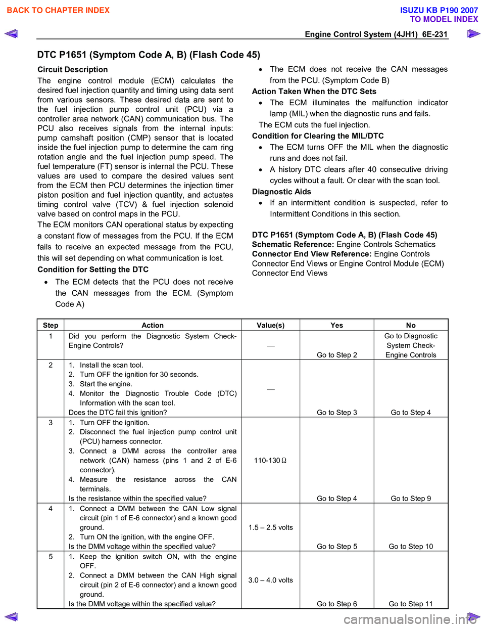
DTC P1651 (Symptom Code A, B) (Flash Code 45)
Circuit Description
The engine control module (ECM) calculates the
desired fuel injection quantity and timing using data sent
from various sensors. These desired data are sent to
the fuel injection pump control unit (PCU) via a
controller area network (CAN) communication bus. The
PCU also receives signals from the internal inputs:
pump camshaft position (CMP) sensor that is located
inside the fuel injection pump to determine the cam ring
rotation angle and the fuel injection pump speed. The
fuel temperature (FT) sensor is internal the PCU. These
values are used to compare the desired values sent
from the ECM then PCU determines the injection time
r
piston position and fuel injection quantity, and actuates
timing control valve (TCV) & fuel injection solenoid
valve based on control maps in the PCU.
The ECM monitors CAN operational status by expecting
a constant flow of messages from the PCU. If the ECM
fails to receive an expected message from the PCU,
this will set depending on what communication is lost.
Condition for Setting the DTC
• The ECM detects that the PCU does not receive
the CAN messages from the ECM. (Symptom
Code A)
•
The ECM does not receive the CAN messages
from the PCU. (Symptom Code B)
Action Taken When the DTC Sets • The ECM illuminates the malfunction indicato
r
lamp (MIL) when the diagnostic runs and fails.
The ECM cuts the fuel injection.
Condition for Clearing the MIL/DTC • The ECM turns OFF the MIL when the diagnostic
runs and does not fail.
• A history DTC clears after 40 consecutive driving
cycles without a fault. Or clear with the scan tool.
Diagnostic Aids
• If an intermittent condition is suspected, refer to
Intermittent Conditions in this section.
DTC P1651 (Symptom Code A, B) (Flash Code 45)
Schematic Reference: Engine Controls Schematics
Connector End View Reference: Engine Controls
Connector End Views or Engine Control Module (ECM)
Connector End Views
Step Action Value(s) Yes No
1 Did you perform the Diagnostic System Check-
Engine Controls?
Go to Step 2 Go to Diagnostic
System Check-
Engine Controls
2 1. Install the scan tool. 2. Turn OFF the ignition for 30 seconds.
3. Start the engine.
4. Monitor the Diagnostic Trouble Code (DTC) Information with the scan tool.
Does the DTC fail this ignition?
Go to Step 3 Go to Step 4
3 1. Turn OFF the ignition. 2. Disconnect the fuel injection pump control unit (PCU) harness connector.
3. Connect a DMM across the controller area network (CAN) harness (pins 1 and 2 of E-6
connector).
4. Measure the resistance across the CAN terminals.
Is the resistance within the specified value? 110-130
Ω
Go to Step 4 Go to Step 9
4 1. Connect a DMM between the CAN Low signal circuit (pin 1 of E-6 connector) and a known good
ground.
2. Turn ON the ignition, with the engine OFF.
Is the DMM voltage within the specified value? 1.5 – 2.5 volts
Go to Step 5 Go to Step 10
5 1. Keep the ignition switch ON, with the engine OFF.
2. Connect a DMM between the CAN High signal circuit (pin 2 of E-6 connector) and a known good
ground.
Is the DMM voltage within the specified value? 3.0 – 4.0 volts
Go to Step 6 Go to Step 11
BACK TO CHAPTER INDEX
TO MODEL INDEX
ISUZU KB P190 2007
Page 1268 of 6020

6E-234 Engine Control System (4JH1)
DTC P1690 (Symptom Code 4) (Flash Code 77)
Circuit Description
The malfunction indicator lamp (MIL) is located on the
instrument panel cluster (IPC). The battery voltage is
supplied to the MIL. The engine control module (ECM)
turns the MIL ON by grounding the MIL control circuit.
After a fixed time passes, the ECM turns OFF the MIL
with the ignition ON and the engine OFF. The MIL has
the following functions:
• The MIL informs the driver that a malfunction has
occurred and the vehicle should be taken in fo
r
service as soon as possible.
• The MIL illuminates during a bulb test and a
system test.
•
A DTC will be stored if a MIL is requested by the
ECM.
If the ECM detects an open circuit or short circuit on the
MIL control circuit, this DTC will set.
Condition for Running the DTC • The ignition switch is ON.
Condition for Setting the DTC
• The ECM detects a low voltage condition on the
MIL control circuit for longer than 3 seconds when
the MIL is commanded OFF.
Action Taken When the DTC Sets • The ECM does not illuminates the MIL when the
diagnostic runs and fails.
Condition for Clearing the DTC • A history DTC clears after 40 consecutive driving
cycles without a fault. Or clear with the scan tool.
Diagnostic Aids
• If an intermittent condition is suspected, refer to
Intermittent Conditions in this section.
DTC P1690 (Symptom Code 4) (Flash Code 77)
Schematic Reference: Engine Controls Schematics
Connector End View Reference: Engine Controls
Connector End Views or Engine Control Module (ECM)
Connector End Views
Step Action Value(s) Yes No
1 Did you perform the Diagnostic System Check-
Engine Controls?
Go to Step 2 Go to Diagnostic
System Check-
Engine Controls
2 1. Install the scan tool. 2. Turn ON the ignition, with the engine OFF.
3. Perform the Malfunction Indicator Lamp (MIL) test with the scan tool.
4. Command the MIL ON with the scan tool.
Does the MIL turn ON when commanded ON with
the scan tool?
Go to Step 3 Go to Step 4
3 Command the MIL OFF with the scan tool. Does the MIL OFF?
Go to Step 17 Go to Step 10
4 1. Turn OFF the ignition.
2. Inspect the Meter (15A) fuse (C-14) in the cabin fuse block.
Is the Meter (15A) fuse (C-14) open?
Go to Step 5 Go to Step 6
5 Replace the Meter (15A) fuse (C-14). If the fuse continues to open, repair the short to ground on one
of the circuits that fed by the Meter (15A) fuse (C-14)
or replace the shorted attached component fed by
the Meter (15A) fuse (C-14).
Did you complete the repair?
Go to Step 19
6 1. Turn OFF the ignition.
2. Disconnect the engine control module (ECM) harness connector.
3. Turn ON the ignition, with the engine OFF.
4. Connect a 3-amp fused jumper wire between the MIL control circuit of the ECM harness connector
(pin 42 of C-56 connector) and a known good
ground.
Does the MIL illuminate?
Go to Step 11 Go to Step 7
BACK TO CHAPTER INDEX
TO MODEL INDEX
ISUZU KB P190 2007
Page 1271 of 6020
Engine Control System (4JH1) 6E-237
DTC P1690 (Symptom Code 8) (Flash Code 77)
Circuit Description
The malfunction indicator lamp (MIL) is located on the
instrument panel cluster (IPC). The battery voltage is
supplied to the MIL. The engine control module (ECM)
turns the MIL ON by grounding the MIL control circuit.
After a fixed time passes, the ECM turns OFF the MIL
with the ignition ON and the engine OFF. The MIL has
the following functions:
• The MIL informs the driver that a malfunction has
occurred and the vehicle should be taken in fo
r
service as soon as possible.
• The MIL illuminates during a bulb test and a
system test.
•
A DTC will be stored if a MIL is requested by the
ECM.
If the ECM detects a short to battery or ignition voltage
on the MIL control circuit, this DTC will set.
Condition for Running the DTC • The ignition switch is ON.
Condition for Setting the DTC
• The ECM detects a high voltage condition on the
MIL control circuit for longer than 1 second when
the MIL is commanded ON.
Action Taken When the DTC Sets
• The ECM does not illuminates the MIL when the
diagnostic runs and fails.
Condition for Clearing the DTC
• A history DTC clears after 40 consecutive driving
cycles without a fault. Or clear with the scan tool.
Diagnostic Aids
• If an intermittent condition is suspected, refer to
Intermittent Conditions in this section.
Test Description
The number below refers to the step number on the
diagnostic table.
3. If the control circuit of the MIL between the ECM and
the IPC is normal, the control circuit voltage low DTC
P1690 (Symptom Code 4) will set.
4. If the control circuit of the MIL between the ECM and
the IPC is normal, the control circuit voltage low DTC
P1690 (Symptom Code 4) will set.
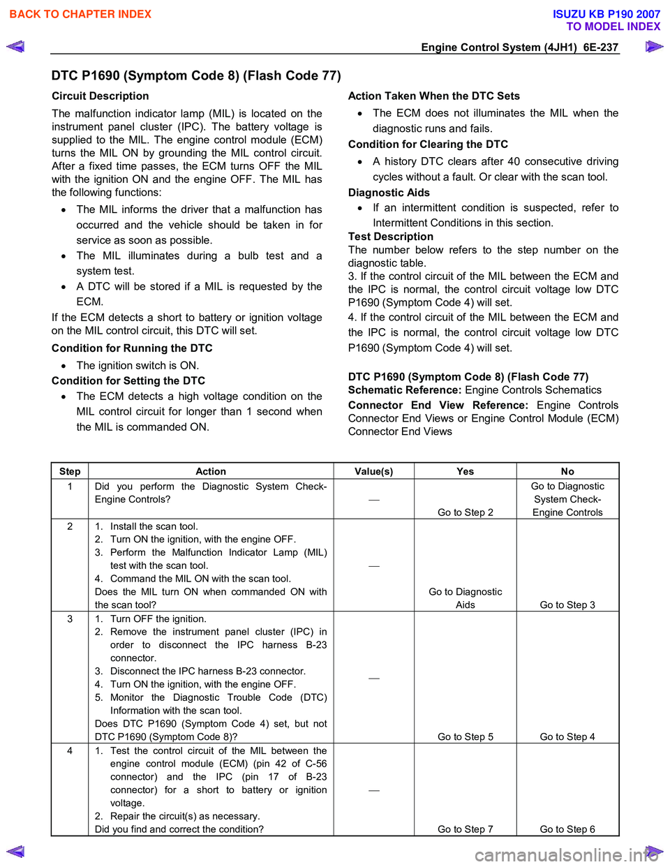
DTC P1690 (Symptom Code 8) (Flash Code 77)
Schematic Reference: Engine Controls Schematics
Connector End View Reference: Engine Controls
Connector End Views or Engine Control Module (ECM)
Connector End Views
Step Action Value(s) Yes No
1 Did you perform the Diagnostic System Check-
Engine Controls?
Go to Step 2 Go to Diagnostic
System Check-
Engine Controls
2 1. Install the scan tool. 2. Turn ON the ignition, with the engine OFF.
3. Perform the Malfunction Indicator Lamp (MIL) test with the scan tool.
4. Command the MIL ON with the scan tool.
Does the MIL turn ON when commanded ON with
the scan tool?
Go to Diagnostic Aids Go to Step 3
3 1. Turn OFF the ignition. 2. Remove the instrument panel cluster (IPC) in order to disconnect the IPC harness B-23
connector.
3. Disconnect the IPC harness B-23 connector.
4. Turn ON the ignition, with the engine OFF.
5. Monitor the Diagnostic Trouble Code (DTC) Information with the scan tool.
Does DTC P1690 (Symptom Code 4) set, but not
DTC P1690 (Symptom Code 8)?
Go to Step 5 Go to Step 4
4 1. Test the control circuit of the MIL between the engine control module (ECM) (pin 42 of C-56
connector) and the IPC (pin 17 of B-23
connector) for a short to battery or ignition
voltage.
2. Repair the circuit(s) as necessary.
Did you find and correct the condition?
Go to Step 7 Go to Step 6
BACK TO CHAPTER INDEX
TO MODEL INDEX
ISUZU KB P190 2007
Page 1310 of 6020
6E-276 Engine Control System (4JH1)
1. Connect the scan tool to the vehicle DLC, with theengine and the scan tool OFF.
2. Turn ON the scan tool.
3. Select Diagnostic > appropriate vehicle identification > Powertrain > 4JH1-TC >
Programming > Program VIN.
4. Input correct VIN reading from stamped VIN o
r
affixed VIN plate on the vehicle.
Select Lock ECU and lock the programmed VIN.
Service Programming System (SPS)
Description
The service programming system (SPS) allows a
technician to program a control module through the data
link connector (DLC). The information transfer circuit that
is used at the DLC is the same serial data circuit used be
the scan tool for retrieving diagnostic trouble codes
(DTCs), displaying data, clearing DTCs etc. This
procedure offers the ability to install software/calibrations
matched to a particular vehicle.
Most control modules have two types of memory. The
software/calibrations reside in the flash memory. The two
types of memory are listed below: • Electrically Erasable Programmable Read Onl
y
Memory (EEPROM).
This type of memory allows selected portions o
f
memory to be programmed while other portions
remain unchanged.
Certain learned values reside in the EEPROM, such as:
- The vehicle identification number (VIN)
- The software/calibrations identification numbers
- The control module security information
• Flash Read Only Memory-Flash Memory
Flash memory has increased memory storage capacity. During programming, all information within
this type of memory is erased, and then replaced
with entirely new information.
Service Programming Methods
The two methods of programming an engine control
module (ECM) are listed below: • Remote Programming
• Pass Thru Programming
For information on programming an ECM using one o
f
the methods listed above, refer to Service Programming
System (SPS) (Remote Procedure) or Service
Programming System (SPS) (Pass-Thru Procedure).
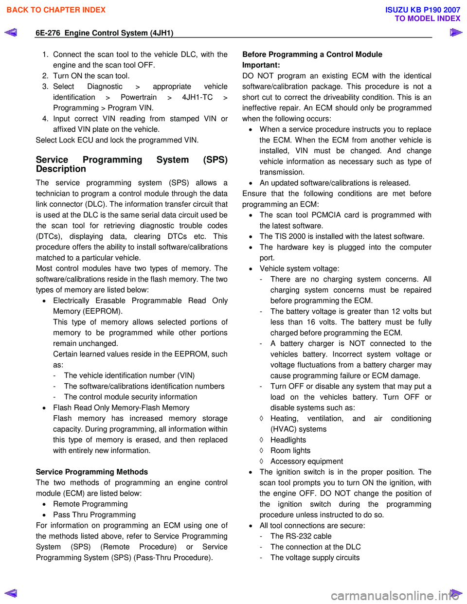
Before Programming a Control Module
Important:
DO NOT program an existing ECM with the identical
software/calibration package. This procedure is not a
short cut to correct the driveability condition. This is an
ineffective repair. An ECM should only be programmed
when the following occurs: • W hen a service procedure instructs you to replace
the ECM. W hen the ECM from another vehicle is
installed, VIN must be changed. And change
vehicle information as necessary such as type o
f
transmission.
• An updated software/calibrations is released.
Ensure that the following conditions are met before
programming an ECM: • The scan tool PCMCIA card is programmed with
the latest software.
• The TIS 2000 is installed with the latest software.
• The hardware key is plugged into the compute
r
port.
• Vehicle system voltage:
- There are no charging system concerns. All charging system concerns must be repaired
before programming the ECM.
- The battery voltage is greater than 12 volts bu
t
less than 16 volts. The battery must be fully
charged before programming the ECM.
-
A battery charger is NOT connected to the
vehicles battery. Incorrect system voltage o
r
voltage fluctuations from a battery charger may
cause programming failure or ECM damage.
- Turn OFF or disable any system that may put a load on the vehicles battery. Turn OFF o
r
disable systems such as:
◊ Heating, ventilation, and air conditioning
(HVAC) systems
◊ Headlights
◊ Room lights
◊ Accessory equipment
• The ignition switch is in the proper position. The
scan tool prompts you to turn ON the ignition, with
the engine OFF. DO NOT change the position o
f
the ignition switch during the programming
procedure unless instructed to do so.
• All tool connections are secure:
- The RS-232 cable
- The connection at the DLC
- The voltage supply circuits
BACK TO CHAPTER INDEX
TO MODEL INDEX
ISUZU KB P190 2007