2007 ISUZU KB P190 ECO mode
[x] Cancel search: ECO modePage 3860 of 6020
Automatic Transmission – 4L60E – Electrical Diagnosis Page 7C2–74
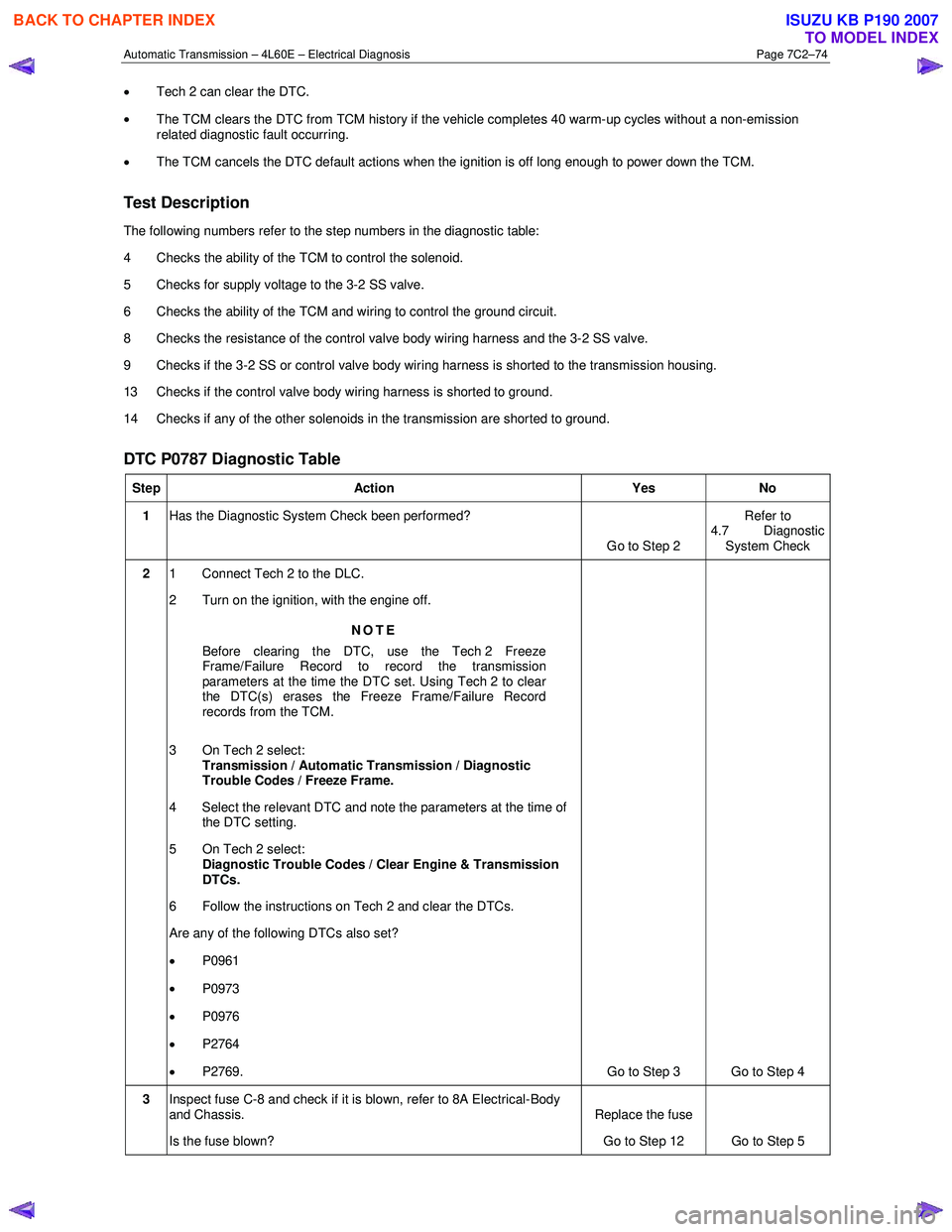
• Tech 2 can clear the DTC.
• The TCM clears the DTC from TCM history if the vehicle completes 40 warm-up cycles without a non-emission
related diagnostic fault occurring.
• The TCM cancels the DTC default actions when the ignition is off long enough to power down the TCM.
Test Description
The following numbers refer to the step numbers in the diagnostic table:
4 Checks the ability of the TCM to control the solenoid.
5 Checks for supply voltage to the 3-2 SS valve.
6 Checks the ability of the TCM and wiring to control the ground circuit.
8 Checks the resistance of the control valve body wiring harness and the 3-2 SS valve.
9 Checks if the 3-2 SS or control valve body wiring harness is shorted to the transmission housing.
13 Checks if the control valve body wiring harness is shorted to ground.
14 Checks if any of the other solenoids in the transmission are shorted to ground.
DTC P0787 Diagnostic Table
Step Action Yes No
1 Has the Diagnostic System Check been performed?
Go to Step 2 Refer to
4.7 Diagnostic System Check
2 1 Connect Tech 2 to the DLC.
2 Turn on the ignition, with the engine off.
NOTE
Before clearing the DTC, use the Tech 2 Freeze
Frame/Failure Record to record the transmission
parameters at the time the DTC set. Using Tech 2 to clear
the DTC(s) erases the Freeze Frame/Failure Record
records from the TCM.
3 On Tech 2 select: Transmission / Automatic Transmission / Diagnostic
Trouble Codes / Freeze Frame.
4 Select the relevant DTC and note the parameters at the time of the DTC setting.
5 On Tech 2 select:
Diagnostic Trouble Codes / Clear Engine & Transmission
DTCs.
6 Follow the instructions on Tech 2 and clear the DTCs.
Are any of the following DTCs also set?
• P0961
• P0973
• P0976
• P2764
• P2769. Go to Step 3 Go to Step 4
3 Inspect fuse C-8 and check if it is blown, refer to 8A Electrical-Body
and Chassis.
Is the fuse blown? Replace the fuse
Go to Step 12 Go to Step 5
BACK TO CHAPTER INDEX
TO MODEL INDEX
ISUZU KB P190 2007
Page 3863 of 6020
Automatic Transmission – 4L60E – Electrical Diagnosis Page 7C2–77
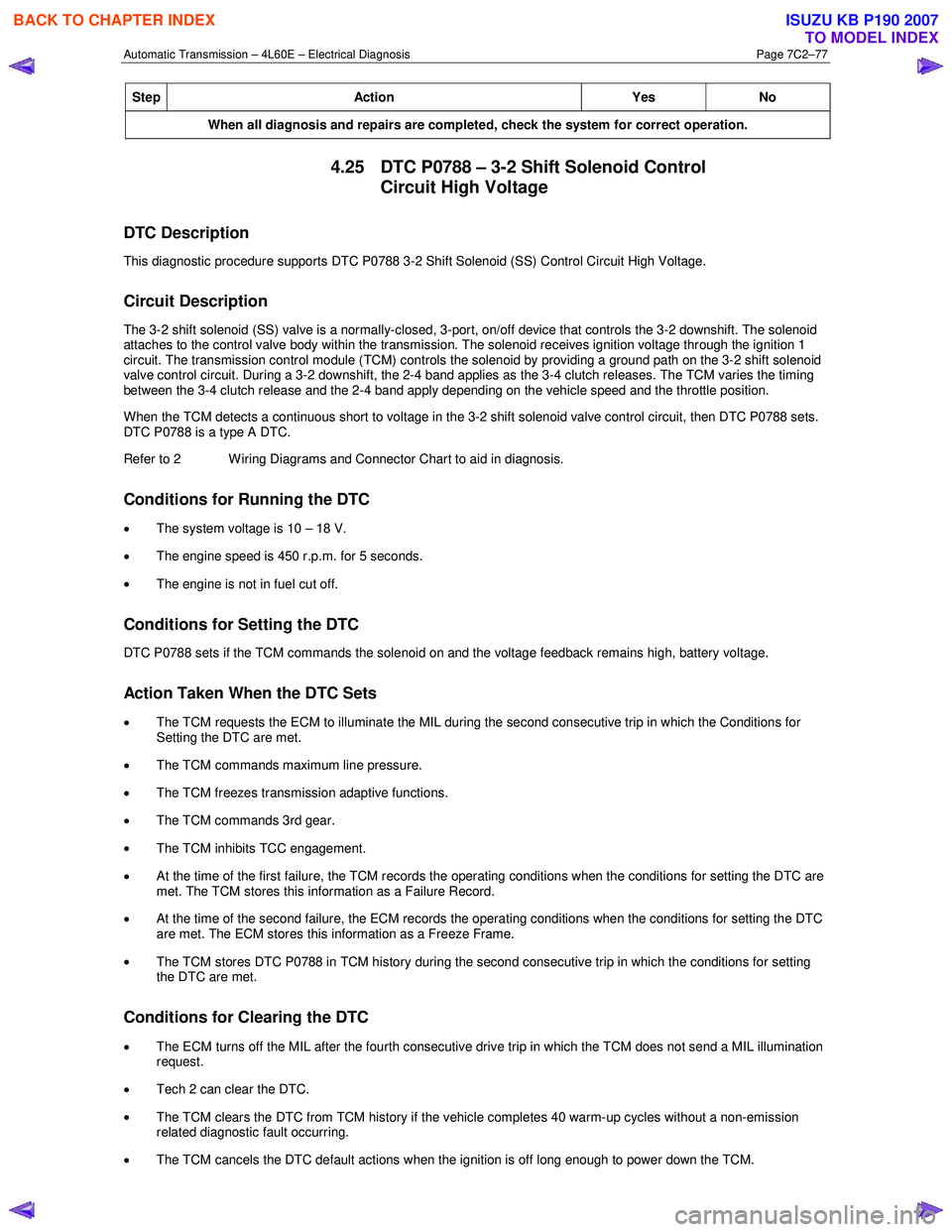
Step Action Yes No
When all diagnosis and repairs are completed, check the system for correct operation.
4.25 DTC P0788 – 3-2 Shift Solenoid Control
Circuit High Voltage
DTC Description
This diagnostic procedure supports DTC P0788 3-2 Shift Solenoid (SS) Control Circuit High Voltage.
Circuit Description
The 3-2 shift solenoid (SS) valve is a normally-closed, 3-port, on/off device that controls the 3-2 downshift. The solenoid
attaches to the control valve body within the transmission. The solenoid receives ignition voltage through the ignition 1
circuit. The transmission control module (TCM) controls the solenoid by providing a ground path on the 3-2 shift solenoid
valve control circuit. During a 3-2 downshift, the 2-4 band applies as the 3-4 clutch releases. The TCM varies the timing
between the 3-4 clutch release and the 2-4 band apply depending on the vehicle speed and the throttle position.
When the TCM detects a continuous short to voltage in the 3-2 shift solenoid valve control circuit, then DTC P0788 sets.
DTC P0788 is a type A DTC.
Refer to 2 W iring Diagrams and Connector Chart to aid in diagnosis.
Conditions for Running the DTC
• The system voltage is 10 – 18 V.
• The engine speed is 450 r.p.m. for 5 seconds.
• The engine is not in fuel cut off.
Conditions for Setting the DTC
DTC P0788 sets if the TCM commands the solenoid on and the voltage feedback remains high, battery voltage.
Action Taken When the DTC Sets
• The TCM requests the ECM to illuminate the MIL during the second consecutive trip in which the Conditions for
Setting the DTC are met.
• The TCM commands maximum line pressure.
• The TCM freezes transmission adaptive functions.
• The TCM commands 3rd gear.
• The TCM inhibits TCC engagement.
• At the time of the first failure, the TCM records the operating conditions when the conditions for setting the DTC are
met. The TCM stores this information as a Failure Record.
• At the time of the second failure, the ECM records the operating conditions when the conditions for setting the DTC
are met. The ECM stores this information as a Freeze Frame.
• The TCM stores DTC P0788 in TCM history during the second consecutive trip in which the conditions for setting
the DTC are met.
Conditions for Clearing the DTC
• The ECM turns off the MIL after the fourth consecutive drive trip in which the TCM does not send a MIL illumination
request.
• Tech 2 can clear the DTC.
• The TCM clears the DTC from TCM history if the vehicle completes 40 warm-up cycles without a non-emission
related diagnostic fault occurring.
• The TCM cancels the DTC default actions when the ignition is off long enough to power down the TCM.
BACK TO CHAPTER INDEX
TO MODEL INDEX
ISUZU KB P190 2007
Page 3864 of 6020
Automatic Transmission – 4L60E – Electrical Diagnosis Page 7C2–78
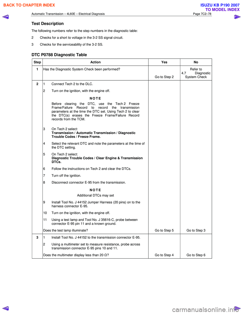
Test Description
The following numbers refer to the step numbers in the diagnostic table:
2 Checks for a short to voltage in the 3-2 SS signal circuit.
3 Checks for the serviceability of the 3-2 SS.
DTC P0788 Diagnostic Table
Step Action Yes No
1 Has the Diagnostic System Check been performed?
Go to Step 2 Refer to
4.7 Diagnostic System Check
2 1 Connect Tech 2 to the DLC.
2 Turn on the ignition, with the engine off.
NOTE
Before clearing the DTC, use the Tech 2 Freeze
Frame/Failure Record to record the transmission
parameters at the time the DTC set. Using Tech 2 to clear
the DTC(s) erases the Freeze Frame/Failure Record
records from the TCM.
3 On Tech 2 select: Transmission / Automatic Transmission / Diagnostic
Trouble Codes / Freeze Frame.
4 Select the relevant DTC and note the parameters at the time of the DTC setting.
5 On Tech 2 select:
Diagnostic Trouble Codes / Clear Engine & Transmission
DTCs.
6 Follow the instructions on Tech 2 and clear the DTCs.
7 Turn off the ignition.
8 Disconnect connector E-95 from the transmission.
NOTE
Additional DTCs may set
9 Install Tool No. J 44152 Jumper Harness (20 pins) on to the harness connector E-95.
10 Turn on the ignition, with the engine off.
11 Using a test lamp and Tool No. J 35616-C, probe between connector E-95 pin 11 and a known ground.
Does the test lamp illuminate? Go to Step 5 Go to Step 3
3 1 Install Tool No. J 44152 to the transmission connector E-95.
2 Using a multimeter set to measure resistance, probe across transmission connector E-95 pins 10 and 11.
Does the multimeter display less than 20 Ω? Go to Step 4 Go to Step 6
BACK TO CHAPTER INDEX
TO MODEL INDEX
ISUZU KB P190 2007
Page 3866 of 6020
Automatic Transmission – 4L60E – Electrical Diagnosis Page 7C2–80
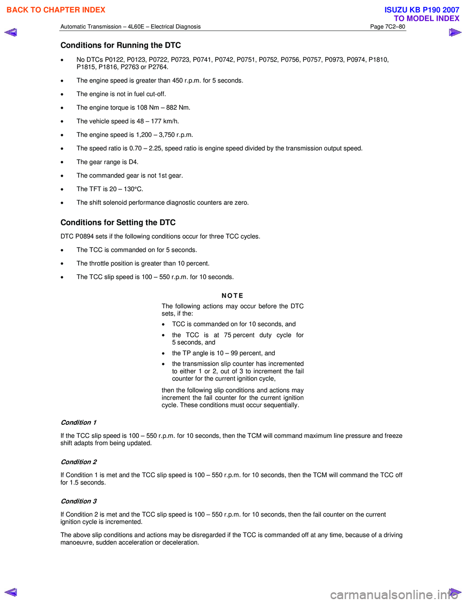
Conditions for Running the DTC
• No DTCs P0122, P0123, P0722, P0723, P0741, P0742, P0751, P0752, P0756, P0757, P0973, P0974, P1810,
P1815, P1816, P2763 or P2764.
• The engine speed is greater than 450 r.p.m. for 5 seconds.
• The engine is not in fuel cut-off.
• The engine torque is 108 Nm – 882 Nm.
• The vehicle speed is 48 – 177 km/h.
• The engine speed is 1,200 – 3,750 r.p.m.
• The speed ratio is 0.70 – 2.25, speed ratio is engine speed divided by the transmission output speed.
• The gear range is D4.
• The commanded gear is not 1st gear.
• The TFT is 20 – 130°C.
• The shift solenoid performance diagnostic counters are zero.
Conditions for Setting the DTC
DTC P0894 sets if the following conditions occur for three TCC cycles.
• The TCC is commanded on for 5 seconds.
• The throttle position is greater than 10 percent.
• The TCC slip speed is 100 – 550 r.p.m. for 10 seconds.
NOTE
The following actions may occur before the DTC
sets, if the:
• TCC is commanded on for 10 seconds, and
• the TCC is at 75 percent duty cycle for
5 seconds, and
• the TP angle is 10 – 99 percent, and
• the transmission slip counter has incremented
to either 1 or 2, out of 3 to increment the fail
counter for the current ignition cycle,
then the following slip conditions and actions may
increment the fail counter for the current ignition
cycle. These conditions must occur sequentially.
Condition 1
If the TCC slip speed is 100 – 550 r.p.m. for 10 seconds, then the TCM will command maximum line pressure and freeze
shift adapts from being updated.
Condition 2
If Condition 1 is met and the TCC slip speed is 100 – 550 r.p.m. for 10 seconds, then the TCM will command the TCC off
for 1.5 seconds.
Condition 3
If Condition 2 is met and the TCC slip speed is 100 – 550 r.p.m. for 10 seconds, then the fail counter on the current
ignition cycle is incremented.
The above slip conditions and actions may be disregarded if the TCC is commanded off at any time, because of a driving
manoeuvre, sudden acceleration or deceleration.
BACK TO CHAPTER INDEX
TO MODEL INDEX
ISUZU KB P190 2007
Page 3867 of 6020
Automatic Transmission – 4L60E – Electrical Diagnosis Page 7C2–81
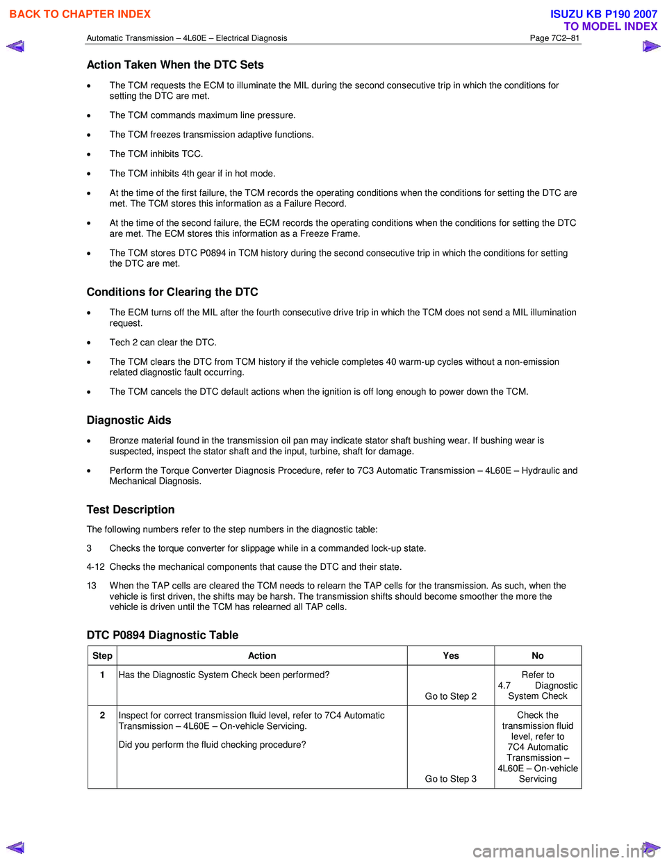
Action Taken When the DTC Sets
• The TCM requests the ECM to illuminate the MIL during the second consecutive trip in which the conditions for
setting the DTC are met.
• The TCM commands maximum line pressure.
• The TCM freezes transmission adaptive functions.
• The TCM inhibits TCC.
• The TCM inhibits 4th gear if in hot mode.
• At the time of the first failure, the TCM records the operating conditions when the conditions for setting the DTC are
met. The TCM stores this information as a Failure Record.
• At the time of the second failure, the ECM records the operating conditions when the conditions for setting the DTC
are met. The ECM stores this information as a Freeze Frame.
• The TCM stores DTC P0894 in TCM history during the second consecutive trip in which the conditions for setting
the DTC are met.
Conditions for Clearing the DTC
• The ECM turns off the MIL after the fourth consecutive drive trip in which the TCM does not send a MIL illumination
request.
• Tech 2 can clear the DTC.
• The TCM clears the DTC from TCM history if the vehicle completes 40 warm-up cycles without a non-emission
related diagnostic fault occurring.
• The TCM cancels the DTC default actions when the ignition is off long enough to power down the TCM.
Diagnostic Aids
•
Bronze material found in the transmission oil pan may indicate stator shaft bushing wear. If bushing wear is
suspected, inspect the stator shaft and the input, turbine, shaft for damage.
• Perform the Torque Converter Diagnosis Procedure, refer to 7C3 Automatic Transmission – 4L60E – Hydraulic and
Mechanical Diagnosis.
Test Description
The following numbers refer to the step numbers in the diagnostic table:
3 Checks the torque converter for slippage while in a commanded lock-up state.
4-12 Checks the mechanical components that cause the DTC and their state.
13 W hen the TAP cells are cleared the TCM needs to relearn the TAP cells for the transmission. As such, when the vehicle is first driven, the shifts may be harsh. The transmission shifts should become smoother the more the
vehicle is driven until the TCM has relearned all TAP cells.
DTC P0894 Diagnostic Table
Step Action Yes No
1 Has the Diagnostic System Check been performed?
Go to Step 2 Refer to
4.7 Diagnostic System Check
2 Inspect for correct transmission fluid level, refer to 7C4 Automatic
Transmission – 4L60E – On-vehicle Servicing.
Did you perform the fluid checking procedure?
Go to Step 3 Check the
transmission fluid level, refer to
7C4 Automatic
Transmission –
4L60E – On-vehicle Servicing
BACK TO CHAPTER INDEX
TO MODEL INDEX
ISUZU KB P190 2007
Page 3868 of 6020
Automatic Transmission – 4L60E – Electrical Diagnosis Page 7C2–82
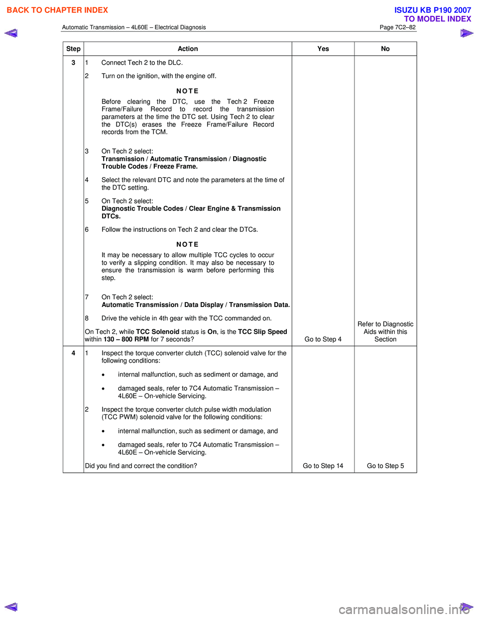
Step Action Yes No
3 1 Connect Tech 2 to the DLC.
2 Turn on the ignition, with the engine off.
NOTE
Before clearing the DTC, use the Tech 2 Freeze
Frame/Failure Record to record the transmission
parameters at the time the DTC set. Using Tech 2 to clear
the DTC(s) erases the Freeze Frame/Failure Record
records from the TCM.
3 On Tech 2 select: Transmission / Automatic Transmission / Diagnostic
Trouble Codes / Freeze Frame.
4 Select the relevant DTC and note the parameters at the time of the DTC setting.
5 On Tech 2 select:
Diagnostic Trouble Codes / Clear Engine & Transmission
DTCs.
6 Follow the instructions on Tech 2 and clear the DTCs.
NOTE
It may be necessary to allow multiple TCC cycles to occur
to verify a slipping condition. It may also be necessary to
ensure the transmission is warm before performing this
step.
7 On Tech 2 select: Automatic Transmission / Data Display / Transmission Data.
8 Drive the vehicle in 4th gear with the TCC commanded on.
On Tech 2, while TCC Solenoid status is On, is the TCC Slip Speed
within 130 – 800 RPM for 7 seconds?
Go to Step 4 Refer to Diagnostic
Aids within this Section
4 1 Inspect the torque converter clutch (TCC) solenoid valve for the
following conditions:
• internal malfunction, such as sediment or damage, and
• damaged seals, refer to 7C4 Automatic Transmission –
4L60E – On-vehicle Servicing.
2 Inspect the torque converter clutch pulse width modulation (TCC PWM) solenoid valve for the following conditions:
• internal malfunction, such as sediment or damage, and
• damaged seals, refer to 7C4 Automatic Transmission –
4L60E – On-vehicle Servicing.
Did you find and correct the condition? Go to Step 14 Go to Step 5
BACK TO CHAPTER INDEX
TO MODEL INDEX
ISUZU KB P190 2007
Page 3872 of 6020
Automatic Transmission – 4L60E – Electrical Diagnosis Page 7C2–86
Step Action Yes No
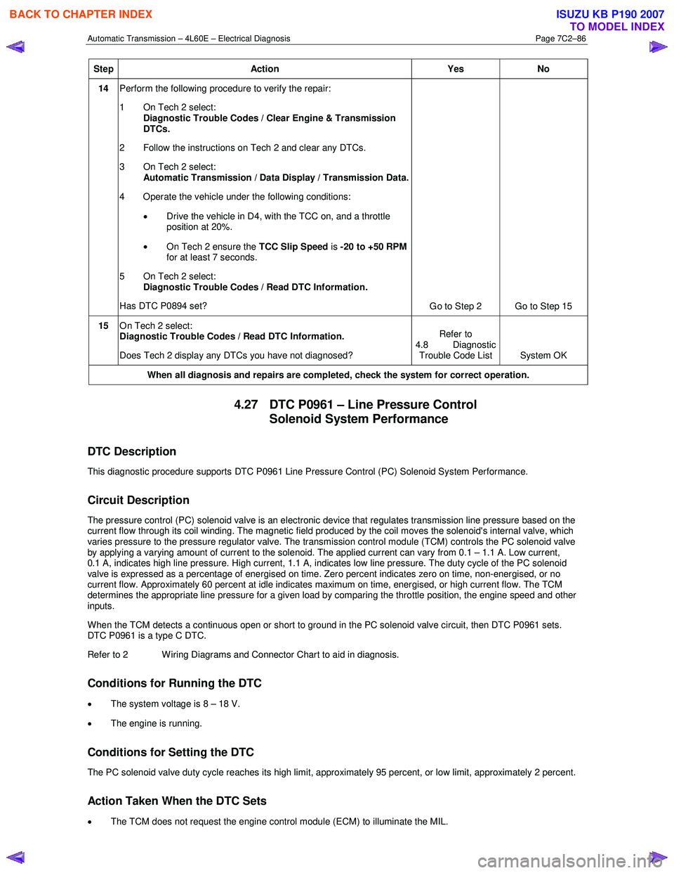
14 Perform the following procedure to verify the repair:
1 On Tech 2 select: Diagnostic Trouble Codes / Clear Engine & Transmission
DTCs.
2 Follow the instructions on Tech 2 and clear any DTCs.
3 On Tech 2 select: Automatic Transmission / Data Display / Transmission Data.
4 Operate the vehicle under the following conditions:
• Drive the vehicle in D4, with the TCC on, and a throttle
position at 20%.
• On Tech 2 ensure the TCC Slip Speed is -20 to +50 RPM
for at least 7 seconds.
5 On Tech 2 select:
Diagnostic Trouble Codes / Read DTC Information.
Has DTC P0894 set? Go to Step 2 Go to Step 15
15 On Tech 2 select:
Diagnostic Trouble Codes / Read DTC Information.
Does Tech 2 display any DTCs you have not diagnosed? Refer to
4.8 Diagnostic Trouble Code List System OK
When all diagnosis and repairs are completed, check the system for correct operation.
4.27 DTC P0961 – Line Pressure Control
Solenoid System Performance
DTC Description
This diagnostic procedure supports DTC P0961 Line Pressure Control (PC) Solenoid System Performance.
Circuit Description
The pressure control (PC) solenoid valve is an electronic device that regulates transmission line pressure based on the
current flow through its coil winding. The magnetic field produced by the coil moves the solenoid's internal valve, which
varies pressure to the pressure regulator valve. The transmission control module (TCM) controls the PC solenoid valve
by applying a varying amount of current to the solenoid. The applied current can vary from 0.1 – 1.1 A. Low current,
0.1 A, indicates high line pressure. High current, 1.1 A, indicates low line pressure. The duty cycle of the PC solenoid
valve is expressed as a percentage of energised on time. Zero percent indicates zero on time, non-energised, or no
current flow. Approximately 60 percent at idle indicates maximum on time, energised, or high current flow. The TCM
determines the appropriate line pressure for a given load by comparing the throttle position, the engine speed and other
inputs.
W hen the TCM detects a continuous open or short to ground in the PC solenoid valve circuit, then DTC P0961 sets.
DTC P0961 is a type C DTC.
Refer to 2 W iring Diagrams and Connector Chart to aid in diagnosis.
Conditions for Running the DTC
• The system voltage is 8 – 18 V.
• The engine is running.
Conditions for Setting the DTC
The PC solenoid valve duty cycle reaches its high limit, approximately 95 percent, or low limit, approximately 2 percent.
Action Taken When the DTC Sets
• The TCM does not request the engine control module (ECM) to illuminate the MIL.
BACK TO CHAPTER INDEX
TO MODEL INDEX
ISUZU KB P190 2007
Page 3873 of 6020
Automatic Transmission – 4L60E – Electrical Diagnosis Page 7C2–87
• The TCM records the operating conditions when the conditions for setting the DTC are met. The TCM records this
information as a Failure Record.
• The TCM freezes transmission adaptive functions.
• The TCM commands maximum line pressure.
• The TCM stores DTC P0961 in TCM history.
Conditions for Clearing the DTC
• The TCM clears the DTC from TCM history if the vehicle completes 40 warm-up cycles without a non-emission
related diagnostic fault occurring.
• Tech 2 can clear the DTC.
Diagnostic Aids
DTC P0961 may set under low voltage conditions caused by high electrical system demands.
Test Description
The following numbers refer to the step numbers in the diagnostic table:
2 Checks the ability of the TCM to control the solenoid.
3 Checks the resistance of the control valve body wiring harness and the PC solenoid.
5 Checks the serviceability of the PC solenoid circuits contained in the control valve body wiring harness.
6-8 Checks the serviceability the power and signal circuits between the TCM and the transmission.
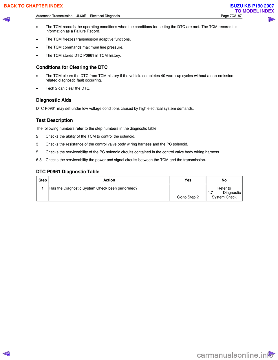
DTC P0961 Diagnostic Table
Step Action Yes No
1 Has the Diagnostic System Check been performed?
Go to Step 2 Refer to
4.7 Diagnostic
System Check
BACK TO CHAPTER INDEX
TO MODEL INDEX
ISUZU KB P190 2007