2007 ISUZU KB P190 display
[x] Cancel search: displayPage 2427 of 6020
ENGINE DRIVEABILITY AND EMISSIONS 6E–257
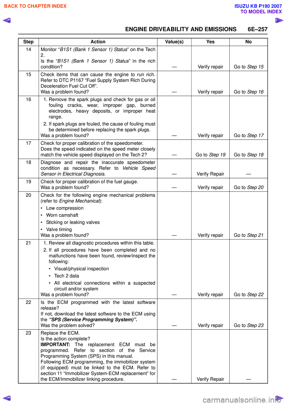
14 Monitor “B1S1 (Bank 1 Sensor 1) Status ” on the Tech
2.
Is the “ B1S1 (Bank 1 Sensor 1) Status ” in the rich
condition? — Verify repair Go to Step 15
15 Check items that can cause the engine to run rich. Refer to DTC P1167 “Fuel Supply System Rich During
Deceleration Fuel Cut Off”.
Was a problem found? — Verify repair Go to Step 16
16 1. Remove the spark plugs and check for gas or oil fouling cracks, wear, improper gap, burned
electrodes, heavy deposits, or improper heat
range.
2. If spark plugs are fouled, the cause of fouling must be determined before replacing the spark plugs.
Was a problem found? — Verify repair Go to Step 17
17 Check for proper calibration of the speedometer. Does the speed indicated on the speed meter closely
match the vehicle speed displayed on the Tech 2? — Go to Step 19Go to Step 18
18 Diagnose and repair the inaccurate speedometer condition as necessary. Refer to Vehicle Speed
Sensor in Electrical Diagnosis . — Verify Repair —
19 Check for proper calibration of the fuel gauge. Was a problem found? — Verify repair Go to Step 20
20 Check for the following engine mechanical problems (refer to Engine Mechanical ):
• Low compression
• Worn camshaft
• Sticking or leaking valves
• Valve timing
Was a problem found? — Verify repair Go to Step 21
21 1. Review all diagnostic procedures within this table. 2. If all procedures have been completed and nomalfunctions have been found, review/inspect the
following:
• Visual/physical inspection
• Tech 2 data
• All electrical connections within a suspected circuit and/or system
Was a problem found? — Verify repair Go to Step 22
22 Is the ECM programmed with the latest software release?
If not, download the latest software to the ECM using
the “SPS (Service Programming System)”.
Was the problem solved? — Verify repair Go to Step 23
23 Replace the ECM. Is the action complete?
IMPORTANT: The replacement ECM must be
programmed. Refer to section of the Service
Programming System (SPS) in this manual.
Following ECM programming, the immobilizer system
(if equipped) must be linked to the ECM. Refer to
section 11 “Immobilizer System-ECM replacement” for
the ECM/Immobilizer linking procedure. — Verify Repair —
Step
Action Value(s) Yes No
BACK TO CHAPTER INDEX
TO MODEL INDEX
ISUZU KB P190 2007
Page 2436 of 6020

6E–266 ENGINE DRIVEABILITY AND EMISSIONS
MANIFOLD ABSOLUTE PRESSURE (MAP)
SENSOR
Location
Installed on the intake manifold.
Removal Procedure 1. Disconenct the negative battery cable.
2. Disconnect a MAP sensor connector from the MAP sensor.
3. Loosen a bolt and remove the MAP sensor from the intake manifold.
4. Remove the MAP sensor from the bracket.
Installation Procedure 1. Tighten the MAP sensor by a bolt with specified tightening torque.
Tightening Torque
• Bolt: 8N·m (0.8kgf·m) 2. Connect a MAP sensor connector to the MAP sensor.
3. Connect the negative battery cable.
NOTE: Verify any DTCs (diagnosis Trouble Code) are
not stored after replacement.
THROTTLE POSITION SENSOR (TPS)
Location
Installed on the throttle body.
Removal Procedure 1. Disconnect the negative battery cable.
2. Disconnect the TPS connector.
3. Loosen two screws and remove TPS from the throttle body.
Installation Procedure 1. Temporary tighten the TPS by two screws.
2. Connect a TPS connectors to the TPS.
3. Connect the Tech2 to the vehicle.
4. Connect the negative battery cable.
5. Select "Data Display" with the Tech2.
6. Check the throttle position data and adjust the TPS position.
7. Tighten two screws.
NOTE: Verify any DTCs (diagnosis Trouble Code) are
not stored after replacement.
BACK TO CHAPTER INDEX
TO MODEL INDEX
ISUZU KB P190 2007
Page 3256 of 6020
Engine Management – V6 – General Information Page 6C1-1–14
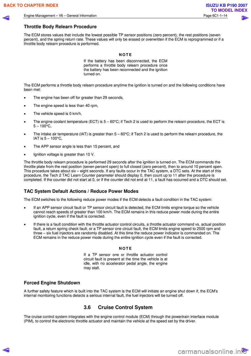
Throttle Body Relearn Procedure
The ECM stores values that include the lowest possible TP sensor positions (zero percent), the rest positions (seven
percent), and the spring return rate. These values will only be erased or overwritten if the ECM is reprogrammed or if a
throttle body relearn procedure is performed.
NOTE
If the battery has been disconnected, the ECM
performs a throttle body relearn procedure once
the battery has been reconnected and the ignition
turned on.
The ECM performs a throttle body relearn procedure anytime the ignition is turned on and the following conditions have
been met:
• The engine has been off for greater than 29 seconds,
• The engine speed is less than 40 rpm,
• The vehicle speed is 0 km/h,
• The engine coolant temperature (ECT) is 5 – 60°C; if Tech 2 is used to perform the relearn procedure, the ECT is
5 – 100°C,
• The intake air temperature (IAT) is greater than 5 – 60°C; if Tech 2 is used to perform the relearn procedure, the
IAT is 5 – 100°C,
• The APP sensor angle is less than 15 percent, and
• Ignition voltage is greater than 10 V.
The throttle body relearn procedure is performed 29 seconds after the ignition is turned on. The ECM commands the
throttle plate from the rest position (seven percent open) to full closed (zero percent), then to around 10 percent open.
This procedure takes about six – eight seconds. If any faults occur in the TAC system, a DTC sets. At the start of this
procedure, the Tech 2 TAC Learn Counter parameter should display 0, then count up to 11 after the procedure is
completed. If the counter did not start at 0, or if the counter did not end at 11, a fault has occurred and a DTC should set.
TAC System Default Actions / Reduce Power Modes
The ECM switches to the following reduce power modes if the ECM detects a fault condition in the TAC system:
• If an APP sensor circuit fault or TP sensor circuit fault is detected, the ECM limits engine torque so the vehicle
cannot reach speeds of greater than 100 km/h. The ECM remains in this reduce power mode during the entire
ignition cycle, even if the fault is corrected.
• If there is a fault condition with the throttle actuator control circuits, a throttle actuator command vs. actual position
fault, a return spring check fault, or a TP sensor one circuit fault, the ECM limits engine speed to 2500 rpm and
three – six fuel injectors are randomly disabled. At this time the reduce power indicator is commanded on. The
ECM remains in the reduce power mode during the entire ignition cycle even if the fault is corrected.
NOTE
If a TP sensor one or throttle actuator control
circuit fault is present at the time the vehicle is at
idle, with no accelerator pedal angle, the engine
may stall.
Forced Engine Shutdown
A further safety feature which is built into the TAC system is the ECM will initiate an engine shut down if, the ECM’s
internal monitoring functions detects a serious internal fault, the fuel injectors will be turned off.
3.6 Cruise Control System
The cruise control system integrates with the engine control module (ECM) through the powertrain interface module
(PIM), to control the electronic throttle actuator and maintain the vehicle at the speed set by the driver.
BACK TO CHAPTER INDEX
TO MODEL INDEX
ISUZU KB P190 2007
Page 3276 of 6020
Engine Management – V6 – General Information Page 6C1-1–34
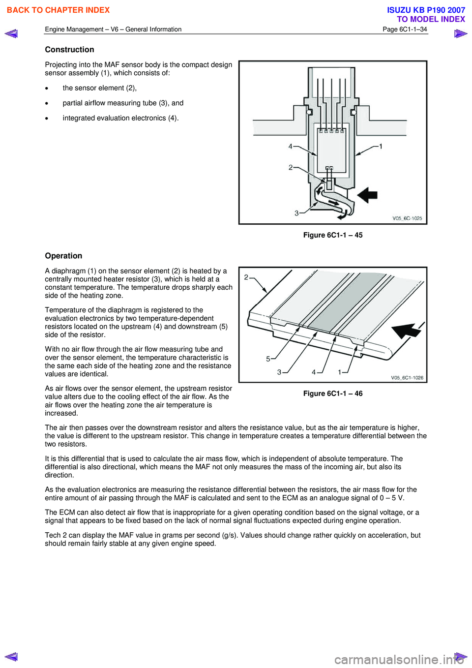
Construction
Projecting into the MAF sensor body is the compact design
sensor assembly (1), which consists of:
• the sensor element (2),
• partial airflow measuring tube (3), and
• integrated evaluation electronics (4).
Figure 6C1-1 – 45
Operation
A diaphragm (1) on the sensor element (2) is heated by a
centrally mounted heater resistor (3), which is held at a
constant temperature. The temperature drops sharply each
side of the heating zone.
Temperature of the diaphragm is registered to the
evaluation electronics by two temperature-dependent
resistors located on the upstream (4) and downstream (5)
side of the resistor.
W ith no air flow through the air flow measuring tube and
over the sensor element, the temperature characteristic is
the same each side of the heating zone and the resistance
values are identical.
As air flows over the sensor element, the upstream resistor
value alters due to the cooling effect of the air flow. As the
air flows over the heating zone the air temperature is
increased.
Figure 6C1-1 – 46
The air then passes over the downstream resistor and alters the resistance value, but as the air temperature is higher,
the value is different to the upstream resistor. This change in temperature creates a temperature differential between the
two resistors.
It is this differential that is used to calculate the air mass flow, which is independent of absolute temperature. The
differential is also directional, which means the MAF not only measures the mass of the incoming air, but also its
direction.
As the evaluation electronics are measuring the resistance differential between the resistors, the air mass flow for the
entire amount of air passing through the MAF is calculated and sent to the ECM as an analogue signal of 0 – 5 V.
The ECM can also detect air flow that is inappropriate for a given operating condition based on the signal voltage, or a
signal that appears to be fixed based on the lack of normal signal fluctuations expected during engine operation.
Tech 2 can display the MAF value in grams per second (g/s). Values should change rather quickly on acceleration, but
should remain fairly stable at any given engine speed.
BACK TO CHAPTER INDEX
TO MODEL INDEX
ISUZU KB P190 2007
Page 3298 of 6020
Engine Management – V6 – Diagnostics Page 6C1-2–20
• Ensure the resistance between the ECM housing and the battery negative cable is less than 0.5 Ω.
• Check the ECM bracket fasteners for correct torque value.
• Check all engine management related components for correct installation.
• Inspect the vacuum hoses for splits, kinks, oil contamination and proper connections, refer to the vehicle emission
control information label. Check the hoses thoroughly for any type of leak or restriction.
• Inspect the air intake ducts for being collapsed, split or for having damaged areas.
• Inspect for air leaks at the throttle body mounting area, mass air flow (MAF) sensor, intake manifold and intake
manifold sealing surfaces.
• Check for wiring harness routing that may be positioned too close to a high voltage or high current device such as
the following:
− Secondary ignition components, and
− Motors and generators.
NOTE
High voltage or high current devices may induce
electrical noise on a circuit, which can interfere
with normal circuit operation.
4.4 Diagnostic System Check
Description
The engine management diagnostic procedure is organised in a logical structure that begins with the Diagnostic System
Check. The Diagnostic System Check directs the diagnostic procedure to the logical steps necessary to diagnose an
engine driveability fault condition.
Test Description
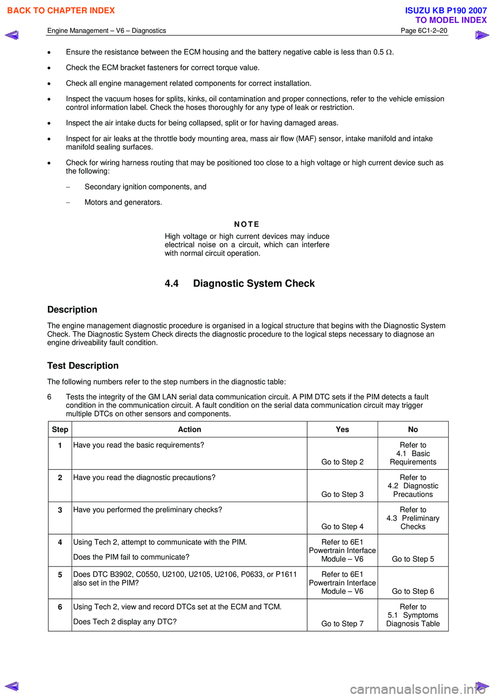
The following numbers refer to the step numbers in the diagnostic table:
6 Tests the integrity of the GM LAN serial data communication circuit. A PIM DTC sets if the PIM detects a fault condition in the communication circuit. A fault condition on the serial data communication circuit may trigger
multiple DTCs on other sensors and components.
Step Action Yes No
1 Have you read the basic requirements?
Go to Step 2 Refer to
4.1 Basic
Requirements
2 Have you read the diagnostic precautions?
Go to Step 3 Refer to
4.2 Diagnostic Precautions
3 Have you performed the preliminary checks?
Go to Step 4 Refer to
4.3 Preliminary Checks
4 Using Tech 2, attempt to communicate with the PIM.
Does the PIM fail to communicate? Refer to 6E1
Powertrain Interface Module – V6 Go to Step 5
5 Does DTC B3902, C0550, U2100, U2105, U2106, P0633, or P1611
also set in the PIM? Refer to 6E1
Powertrain Interface Module – V6 Go to Step 6
6 Using Tech 2, view and record DTCs set at the ECM and TCM.
Does Tech 2 display any DTC? Go to Step 7 Refer to
5.1 Symptoms
Diagnosis Table
BACK TO CHAPTER INDEX
TO MODEL INDEX
ISUZU KB P190 2007
Page 3299 of 6020
Engine Management – V6 – Diagnostics Page 6C1-2–21
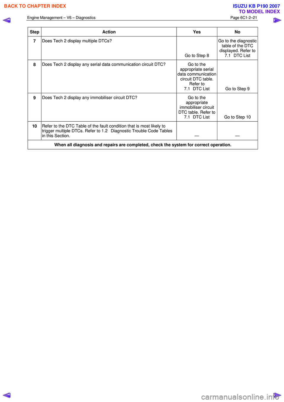
Step Action Yes No
7 Does Tech 2 display multiple DTCs?
Go to Step 8 Go to the diagnostic
table of the DTC
displayed. Refer to 7.1 DTC List
8 Does Tech 2 display any serial data communication circuit DTC? Go to the
appropriate serial
data communication circuit DTC table. Refer to
7.1 DTC List Go to Step 9
9 Does Tech 2 display any immobiliser circuit DTC? Go to the
appropriate
immobiliser circuit
DTC table. Refer to 7.1 DTC List Go to Step 10
10 Refer to the DTC Table of the fault condition that is most likely to
trigger multiple DTCs. Refer to 1.2 Diagnostic Trouble Code Tables
in this Section. — —
When all diagnosis and repairs are completed, check the system for correct operation.
BACK TO CHAPTER INDEX
TO MODEL INDEX
ISUZU KB P190 2007
Page 3315 of 6020
Engine Management – V6 – Diagnostics Page 6C1-2–37
6 Functional Checks
6.1 General Information
The items detailed in the following pages are to be used when there is a customer complaint and there are no diagnostic
trouble codes set, or one or more of the Tech 2 data values are not within the typical values. They are also to be used
when instructed from a DTC table. Before using these tables, you should refer to 5 Symptoms Diagnostics in this
Section, which may direct you to using the following functional checks.
The purpose of these tables is to diagnose engine control module (ECM) controlled components or sub-systems that do
not have diagnostic trouble codes assigned to them. Another purpose of these tables is for Technicians who feel
confident that a particular part of the sub-system is not operating properly and wants only to check that particular item
for proper operation without going through lengthy diagnostic procedures.
6.2 Fuel Injector Coil Test
The fuel injector coil test is divided into two parts. Begin by performing the fuel injector coil quick test. Then only perform
the Injector Coil Test – W ith Special Tool J39021 procedure if the quick test determines that there is a faulty fuel injector.
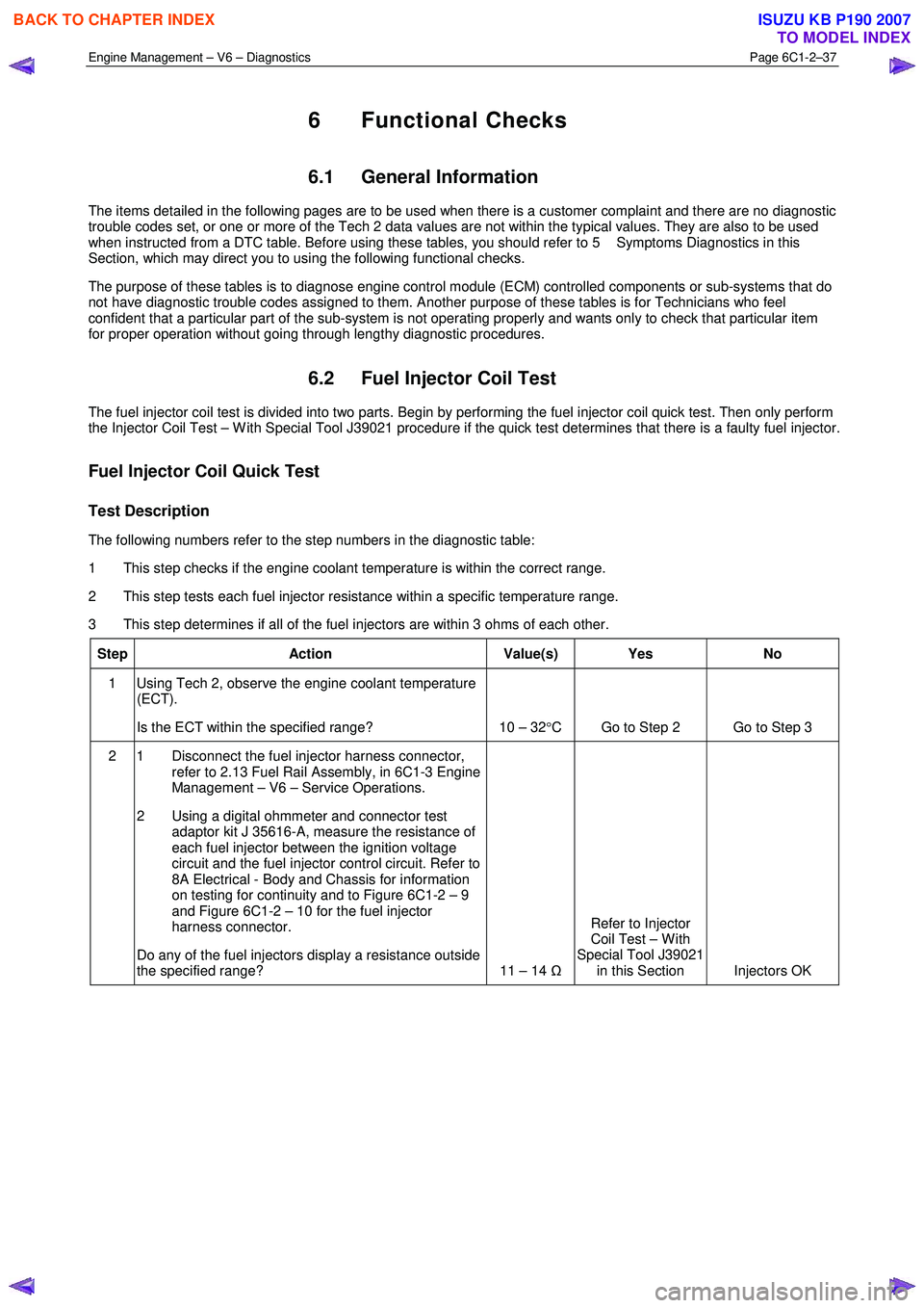
Fuel Injector Coil Quick Test
Test Description
The following numbers refer to the step numbers in the diagnostic table:
1 This step checks if the engine coolant temperature is within the correct range.
2 This step tests each fuel injector resistance within a specific temperature range.
3 This step determines if all of the fuel injectors are within 3 ohms of each other.
Step Action Value(s) Yes No
1 Using Tech 2, observe the engine coolant temperature
(ECT).
Is the ECT within the specified range? 10 – 32 °C Go to Step 2 Go to Step 3
2 1 Disconnect the fuel injector harness connector,
refer to 2.13 Fuel Rail Assembly, in 6C1-3 Engine
Management – V6 – Service Operations.
2 Using a digital ohmmeter and connector test adaptor kit J 35616-A, measure the resistance of
each fuel injector between the ignition voltage
circuit and the fuel injector control circuit. Refer to
8A Electrical - Body and Chassis for information
on testing for continuity and to Figure 6C1-2 – 9
and Figure 6C1-2 – 10 for the fuel injector
harness connector.
Do any of the fuel injectors display a resistance outside
the specified range? 11 – 14 ΩRefer to Injector
Coil Test – W ith
Special Tool J39021 in this Section Injectors OK
BACK TO CHAPTER INDEX
TO MODEL INDEX
ISUZU KB P190 2007
Page 3325 of 6020
Engine Management – V6 – Diagnostics Page 6C1-2–47
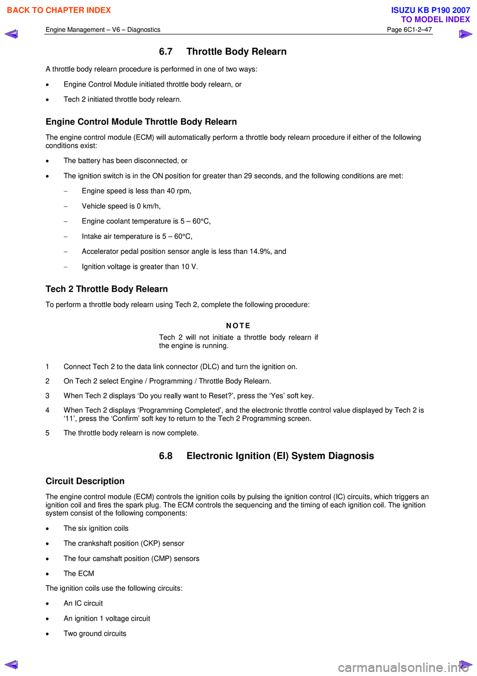
6.7 Throttle Body Relearn
A throttle body relearn procedure is performed in one of two ways:
• Engine Control Module initiated throttle body relearn, or
• Tech 2 initiated throttle body relearn.
Engine Control Module Throttle Body Relearn
The engine control module (ECM) will automatically perform a throttle body relearn procedure if either of the following
conditions exist:
• The battery has been disconnected, or
• The ignition switch is in the ON position for greater than 29 seconds, and the following conditions are met:
− Engine speed is less than 40 rpm,
− Vehicle speed is 0 km/h,
− Engine coolant temperature is 5 – 60°C,
− Intake air temperature is 5 – 60°C,
− Accelerator pedal position sensor angle is less than 14.9%, and
− Ignition voltage is greater than 10 V.
Tech 2 Throttle Body Relearn
To perform a throttle body relearn using Tech 2, complete the following procedure:
NOTE
Tech 2 will not initiate a throttle body relearn if
the engine is running.
1 Connect Tech 2 to the data link connector (DLC) and turn the ignition on.
2 On Tech 2 select Engine / Programming / Throttle Body Relearn.
3 W hen Tech 2 displays ‘Do you really want to Reset?’, press the ‘Yes’ soft key.
4 W hen Tech 2 displays ‘Programming Completed’, and the electronic throttle control value displayed by Tech 2 is ‘11’, press the ‘Confirm’ soft key to return to the Tech 2 Programming screen.
5 The throttle body relearn is now complete.
6.8 Electronic Ignition (EI) System Diagnosis
Circuit Description
The engine control module (ECM) controls the ignition coils by pulsing the ignition control (IC) circuits, which triggers an
ignition coil and fires the spark plug. The ECM controls the sequencing and the timing of each ignition coil. The ignition
system consist of the following components:
• The six ignition coils
• The crankshaft position (CKP) sensor
• The four camshaft position (CMP) sensors
• The ECM
The ignition coils use the following circuits:
• An IC circuit
• An ignition 1 voltage circuit
• Two ground circuits
BACK TO CHAPTER INDEX
TO MODEL INDEX
ISUZU KB P190 2007