2007 ISUZU KB P190 Diagram
[x] Cancel search: DiagramPage 3449 of 6020
Engine Management – V6 – Diagnostics Page 6C1-2–171
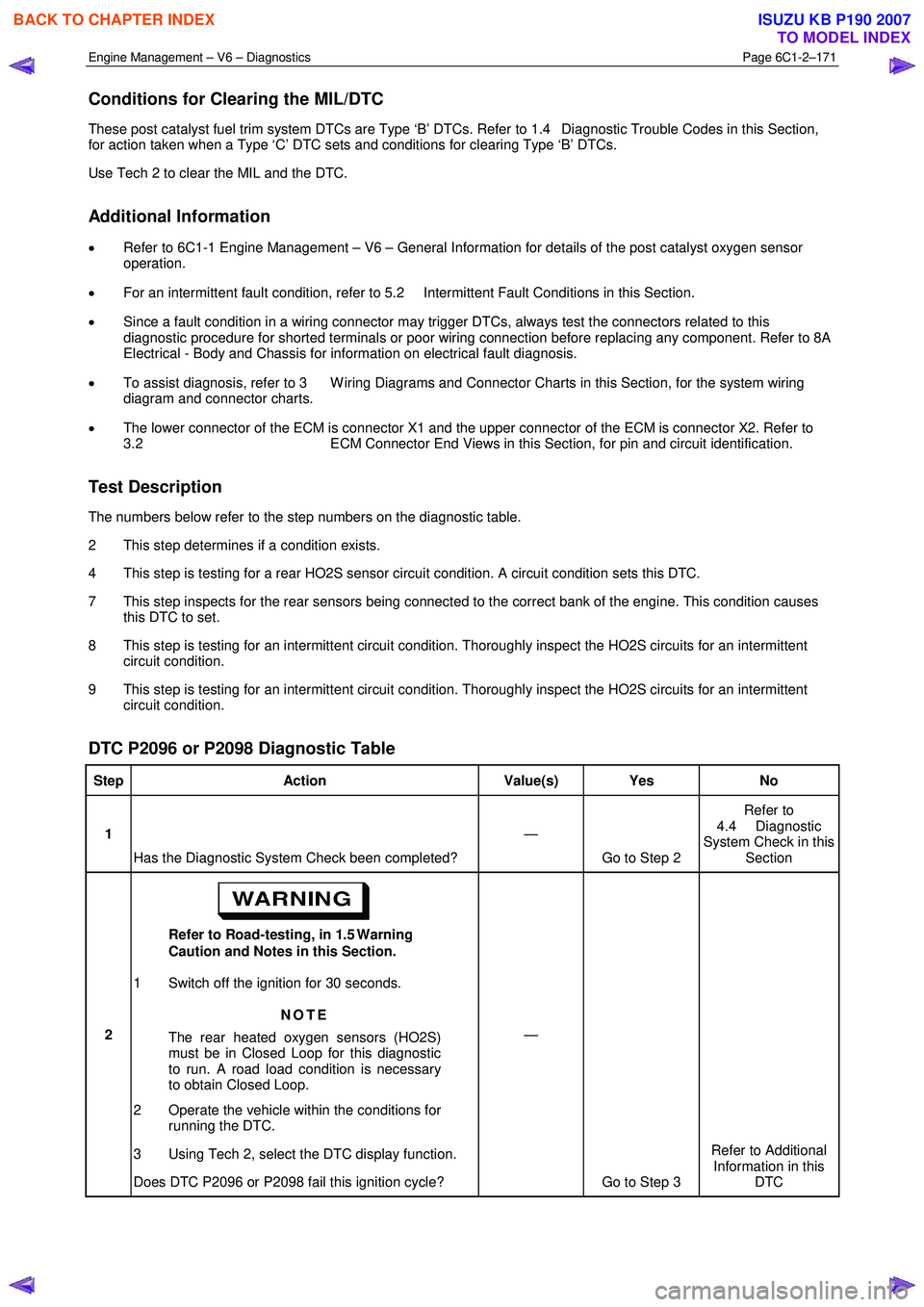
Conditions for Clearing the MIL/DTC
These post catalyst fuel trim system DTCs are Type ‘B’ DTCs. Refer to 1.4 Diagnostic Trouble Codes in this Section,
for action taken when a Type ‘C’ DTC sets and conditions for clearing Type ‘B’ DTCs.
Use Tech 2 to clear the MIL and the DTC.
Additional Information
• Refer to 6C1-1 Engine Management – V6 – General Information for details of the post catalyst oxygen sensor
operation.
• For an intermittent fault condition, refer to 5.2 Intermittent Fault Conditions in this Section.
• Since a fault condition in a wiring connector may trigger DTCs, always test the connectors related to this
diagnostic procedure for shorted terminals or poor wiring connection before replacing any component. Refer to 8A
Electrical - Body and Chassis for information on electrical fault diagnosis.
• To assist diagnosis, refer to 3 W iring Diagrams and Connector Charts in this Section, for the system wiring
diagram and connector charts.
• The lower connector of the ECM is connector X1 and the upper connector of the ECM is connector X2. Refer to
3.2 ECM Connector End Views in this Section, for pin and circuit identification.
Test Description
The numbers below refer to the step numbers on the diagnostic table.
2 This step determines if a condition exists.
4 This step is testing for a rear HO2S sensor circuit condition. A circuit condition sets this DTC.
7 This step inspects for the rear sensors being connected to the correct bank of the engine. This condition causes this DTC to set.
8 This step is testing for an intermittent circuit condition. Thoroughly inspect the HO2S circuits for an intermittent circuit condition.
9 This step is testing for an intermittent circuit condition. Thoroughly inspect the HO2S circuits for an intermittent circuit condition.
DTC P2096 or P2098 Diagnostic Table
Step Action Value(s) Yes No
1
Has the Diagnostic System Check been completed? —
Go to Step 2 Refer to
4.4 Diagnostic
System Check in this Section
2 Refer to Road-testing, in 1.5 Warning
Caution and Notes in this Section.
1 Switch off the ignition for 30 seconds.
NOTE
The rear heated oxygen sensors (HO2S)
must be in Closed Loop for this diagnostic
to run. A road load condition is necessary
to obtain Closed Loop.
2 Operate the vehicle within the conditions for running the DTC.
3 Using Tech 2, select the DTC display function.
Does DTC P2096 or P2098 fail this ignition cycle? —
Go to Step 3 Refer to Additional
Information in this DTC
BACK TO CHAPTER INDEX
TO MODEL INDEX
ISUZU KB P190 2007
Page 3453 of 6020
Engine Management – V6 – Diagnostics Page 6C1-2–175
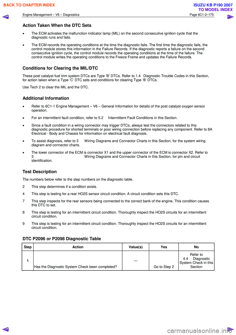
Action Taken When the DTC Sets
• The ECM activates the malfunction indicator lamp (MIL) on the second consecutive ignition cycle that the
diagnostic runs and fails.
• The ECM records the operating conditions at the time the diagnostic fails. The first time the diagnostic fails, the
control module stores this information in the Failure Records. If the diagnostic reports a failure on the second
consecutive ignition cycle, the control module records the operating conditions at the time of the failure. The
control module writes the operating conditions to the Freeze Frame and updates the Failure Records.
Conditions for Clearing the MIL/DTC
These post catalyst fuel trim system DTCs are Type ‘B’ DTCs. Refer to 1.4 Diagnostic Trouble Codes in this Section,
for action taken when a Type ‘C’ DTC sets and conditions for clearing Type ‘B’ DTCs.
Use Tech 2 to clear the MIL and the DTC.
Additional Information
• Refer to 6C1-1 Engine Management – V6 – General Information for details of the post catalyst oxygen sensor
operation.
• For an intermittent fault condition, refer to 5.2 Intermittent Fault Conditions in this Section.
• Since a fault condition in a wiring connector may trigger DTCs, always test the connectors related to this
diagnostic procedure for shorted terminals or poor wiring connection before replacing any component. Refer to 8A
Electrical - Body and Chassis for information on electrical fault diagnosis.
• To assist diagnosis, refer to 3 W iring Diagrams and Connector Charts in this Section, for the system wiring
diagram and connector charts.
• The lower connector of the ECM is connector X1 and the upper connector of the ECM is connector X2. Refer to
3 W iring Diagrams and Connector Charts in this Section, for pin and circuit
identification.
Test Description
The numbers below refer to the step numbers on the diagnostic table.
2 This step determines if a condition exists.
4 This step is testing for a rear HO2S sensor circuit condition. A circuit condition sets this DTC.
7 This step inspects for the rear sensors being connected to the correct bank of the engine. This condition causes this DTC to set.
8 This step is testing for an intermittent circuit condition. Thoroughly inspect the HO2S circuits for an intermittent circuit condition.
9 This step is testing for an intermittent circuit condition. Thoroughly inspect the HO2S circuits for an intermittent circuit condition.
DTC P2096 or P2098 Diagnostic Table
Step Action Value(s) Yes No
1
Has the Diagnostic System Check been completed? —
Go to Step 2 Refer to
4.4 Diagnostic
System Check in this Section
BACK TO CHAPTER INDEX
TO MODEL INDEX
ISUZU KB P190 2007
Page 3456 of 6020
Engine Management – V6 – Diagnostics Page 6C1-2–178
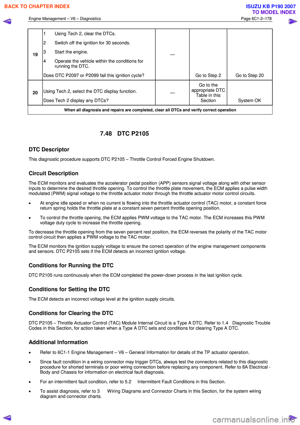
19 1 Using Tech 2, clear the DTCs.
2 Switch off the ignition for 30 seconds.
3 Start the engine.
4 Operate the vehicle within the conditions for running the DTC.
Does DTC P2097 or P2099 fail this ignition cycle? —
Go to Step 2 Go to Step 20
20 Using Tech 2, select the DTC display function.
Does Tech 2 display any DTCs? —
Go to the
appropriate DTC Table in this Section System OK
When all diagnosis and repairs are completed, clear all DTCs and verify correct operation
7.48 DTC P2105
DTC Descriptor
This diagnostic procedure supports DTC P2105 – Throttle Control Forced Engine Shutdown.
Circuit Description
The ECM monitors and evaluates the accelerator pedal position (APP) sensors signal voltage along with other sensor
inputs to determine the desired throttle opening. To control the throttle plate movement, the ECM applies a pulse width
modulated (PW M) signal voltage to the throttle actuator motor through the throttle actuator motor control circuits.
• At engine idle speed or when no current is flowing into the throttle actuator control (TAC) motor, a constant force
return spring holds the throttle plate at a constant seven percent throttle opening position.
• To control the throttle opening, the ECM applies PW M voltage to the TAC motor. The ECM increases this PW M
voltage duty cycle to increase the throttle opening.
To decrease the throttle opening from the seven percent rest position, the ECM reverses the polarity of the TAC motor
control circuit then applies a PW M voltage to the TAC motor.
The ECM monitors the ignition supply voltage to ensure the correct operation of the engine management components
and sensors. DTC P2105 sets if the ECM detects an incorrect ignition voltage.
Conditions for Running the DTC
DTC P2105 runs continuously when the ECM completed the power-down process in the last ignition cycle.
Conditions for Setting the DTC
The ECM detects an incorrect voltage level at the ignition supply circuits.
Conditions for Clearing the DTC
DTC P2105 – Throttle Actuator Control (TAC) Module Internal Circuit is a Type A DTC. Refer to 1.4 Diagnostic Trouble
Codes in this Section, for action taken when a Type A DTC sets and conditions for clearing Type A DTC.
Additional Information
• Refer to 6C1-1 Engine Management – V6 – General Information for details of the TP actuator operation.
• Since fault condition in a wiring connector may trigger DTCs, always test the connectors related to this diagnostic
procedure for shorted terminals or poor wiring connection before replacing any component. Refer to 8A Electrical -
Body and Chassis for information on electrical fault diagnosis.
• For an intermittent fault condition, refer to 5.2 Intermittent Fault Conditions in this Section.
• To assist diagnosis, refer to 3 W iring Diagrams and Connector Charts in this Section, for the system wiring
diagram and connector charts.
BACK TO CHAPTER INDEX
TO MODEL INDEX
ISUZU KB P190 2007
Page 3459 of 6020
Engine Management – V6 – Diagnostics Page 6C1-2–181
Additional Information
• Refer to 6C1-1 Engine Management – V6 – General Information for details of the TP sensor operation.
• For an intermittent fault condition, refer to 5.2 Intermittent Fault Conditions in this Section.
• Since fault condition in a wiring connector may trigger DTCs, always test the connectors related to this diagnostic
procedure for shorted terminals or poor wiring connection before replacing any component. Refer to 8A Electrical -
Body and Chassis for information on electrical fault diagnosis.
• To assist diagnosis, refer to 3 W iring Diagrams and Connector Charts in this Section, for the system wiring
diagram and connector charts.
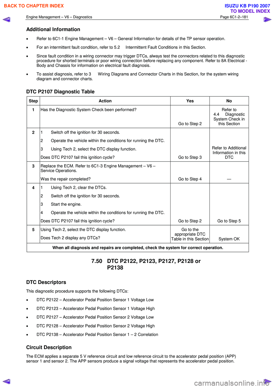
DTC P2107 Diagnostic Table
Step Action Yes No
1 Has the Diagnostic System Check been performed?
Go to Step 2 Refer to
4.4 Diagnostic
System Check in this Section
2 1 Switch off the ignition for 30 seconds.
2 Operate the vehicle within the conditions for running the DTC.
3 Using Tech 2, select the DTC display function.
Does DTC P2107 fail this ignition cycle? Go to Step 3 Refer to Additional
Information in this DTC
3 Replace the ECM. Refer to 6C1-3 Engine Management – V6 –
Service Operations.
W as the repair completed? Go to Step 4 —
4 1 Using Tech 2, clear the DTCs.
2 Switch off the ignition for 30 seconds.
3 Start the engine.
4 Operate the vehicle within the conditions for running the DTC.
Does DTC P2107 fail this ignition cycle? Go to Step 2 Go to Step 5
5 Using Tech 2, select the DTC display function.
Does Tech 2 display any DTCs? Go to the
appropriate DTC
Table in this Section System OK
When all diagnosis and repairs are completed, check the system for correct operation.
7.50 DTC P2122, P2123, P2127, P2128 or
P2138
DTC Descriptors
This diagnostic procedure supports the following DTCs:
• DTC P2122 – Accelerator Pedal Position Sensor 1 Voltage Low
• DTC P2123 – Accelerator Pedal Position Sensor 1 Voltage High
• DTC P2127 – Accelerator Pedal Position Sensor 2 Voltage Low
• DTC P2128 – Accelerator Pedal Position Sensor 2 Voltage High
• DTC P2138 – Accelerator Pedal Position Sensor 1 – 2 Correlation
Circuit Description
The ECM applies a separate 5 V reference circuit and low reference circuit to the accelerator pedal position (APP)
sensor 1 and sensor 2. The APP sensors produce a signal voltage that represents the accelerator pedal position.
BACK TO CHAPTER INDEX
TO MODEL INDEX
ISUZU KB P190 2007
Page 3460 of 6020
Engine Management – V6 – Diagnostics Page 6C1-2–182
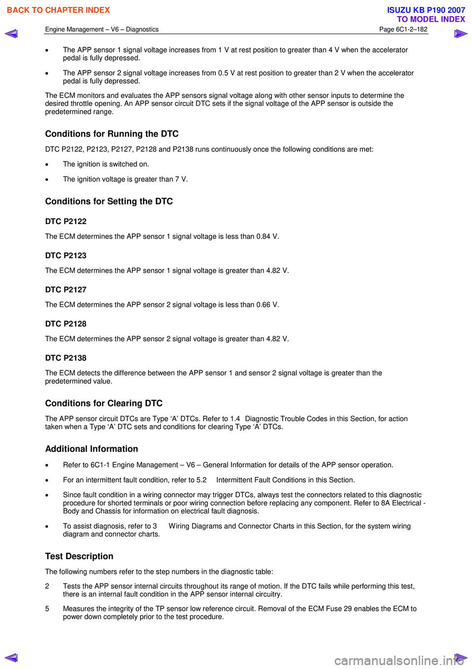
• The APP sensor 1 signal voltage increases from 1 V at rest position to greater than 4 V when the accelerator
pedal is fully depressed.
• The APP sensor 2 signal voltage increases from 0.5 V at rest position to greater than 2 V when the accelerator
pedal is fully depressed.
The ECM monitors and evaluates the APP sensors signal voltage along with other sensor inputs to determine the
desired throttle opening. An APP sensor circuit DTC sets if the signal voltage of the APP sensor is outside the
predetermined range.
Conditions for Running the DTC
DTC P2122, P2123, P2127, P2128 and P2138 runs continuously once the following conditions are met:
• The ignition is switched on.
• The ignition voltage is greater than 7 V.
Conditions for Setting the DTC
DTC P2122
The ECM determines the APP sensor 1 signal voltage is less than 0.84 V.
DTC P2123
The ECM determines the APP sensor 1 signal voltage is greater than 4.82 V.
DTC P2127
The ECM determines the APP sensor 2 signal voltage is less than 0.66 V.
DTC P2128
The ECM determines the APP sensor 2 signal voltage is greater than 4.82 V.
DTC P2138
The ECM detects the difference between the APP sensor 1 and sensor 2 signal voltage is greater than the
predetermined value.
Conditions for Clearing DTC
The APP sensor circuit DTCs are Type ‘A’ DTCs. Refer to 1.4 Diagnostic Trouble Codes in this Section, for action
taken when a Type ‘A’ DTC sets and conditions for clearing Type ‘A’ DTCs.
Additional Information
• Refer to 6C1-1 Engine Management – V6 – General Information for details of the APP sensor operation.
• For an intermittent fault condition, refer to 5.2 Intermittent Fault Conditions in this Section.
• Since fault condition in a wiring connector may trigger DTCs, always test the connectors related to this diagnostic
procedure for shorted terminals or poor wiring connection before replacing any component. Refer to 8A Electrical -
Body and Chassis for information on electrical fault diagnosis.
• To assist diagnosis, refer to 3 W iring Diagrams and Connector Charts in this Section, for the system wiring
diagram and connector charts.
Test Description
The following numbers refer to the step numbers in the diagnostic table:
2 Tests the APP sensor internal circuits throughout its range of motion. If the DTC fails while performing this test, there is an internal fault condition in the APP sensor internal circuitry.
5 Measures the integrity of the TP sensor low reference circuit. Removal of the ECM Fuse 29 enables the ECM to power down completely prior to the test procedure.
BACK TO CHAPTER INDEX
TO MODEL INDEX
ISUZU KB P190 2007
Page 3463 of 6020
Engine Management – V6 – Diagnostics Page 6C1-2–185
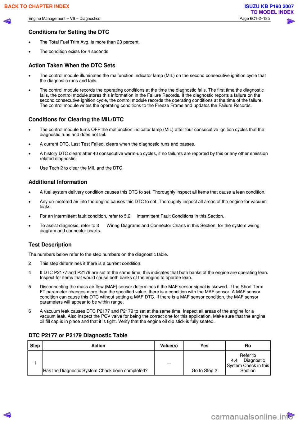
Conditions for Setting the DTC
• The Total Fuel Trim Avg. is more than 23 percent.
• The condition exists for 4 seconds.
Action Taken When the DTC Sets
• The control module illuminates the malfunction indicator lamp (MIL) on the second consecutive ignition cycle that
the diagnostic runs and fails.
• The control module records the operating conditions at the time the diagnostic fails. The first time the diagnostic
fails, the control module stores this information in the Failure Records. If the diagnostic reports a failure on the
second consecutive ignition cycle, the control module records the operating conditions at the time of the failure.
The control module writes the operating conditions to the Freeze Frame and updates the Failure Records.
Conditions for Clearing the MIL/DTC
• The control module turns OFF the malfunction indicator lamp (MIL) after four consecutive ignition cycles that the
diagnostic runs and does not fail.
• A current DTC, Last Test Failed, clears when the diagnostic runs and passes.
• A history DTC clears after 40 consecutive warm-up cycles, if no failures are reported by this or any other emission
related diagnostic.
• Use Tech 2 to clear the MIL and the DTC.
Additional Information
• A fuel system delivery condition causes this DTC to set. Thoroughly inspect all items that cause a lean condition.
• Any un-metered air into the engine causes this DTC to set. Thoroughly inspect all areas of the engine for vacuum
leaks.
• For an intermittent fault condition, refer to 5.2 Intermittent Fault Conditions in this Section.
• To assist diagnosis, refer to 3 W iring Diagrams and Connector Charts in this Section, for the system wiring
diagram and connector charts.
Test Description
The numbers below refer to the step numbers on the diagnostic table.
2 This step determines if there is a current condition.
4 If DTC P2177 and P2179 are set at the same time, this indicates that both banks of the engine are operating lean. Inspect for items that would cause both banks of the engine to operate lean.
5 Disconnecting the mass air flow (MAF) sensor determines if the MAF sensor signal is skewed. If the Short Term FT parameter changes more than the specified value, there is a condition with the MAF sensor. A MAF sensor
condition can cause this DTC without setting a MAF DTC. If there is a MAF sensor condition, the MAF sensor
parameters will appear to be within range.
6 A vacuum leak causes DTC P2177 and P2179 to set at the same time. Inspect all areas of the engine for a vacuum leak. Also inspect the PCV valve for being the correct one for this application. Make sure that the engine
oil fill cap is in place and that it is tight. Verify that the engine oil dip stick is fully seated.
DTC P2177 or P2179 Diagnostic Table
Step Action Value(s) Yes No
1
Has the Diagnostic System Check been completed? —
Go to Step 2 Refer to
4.4 Diagnostic
System Check in this Section
BACK TO CHAPTER INDEX
TO MODEL INDEX
ISUZU KB P190 2007
Page 3467 of 6020
Engine Management – V6 – Diagnostics Page 6C1-2–189
• For an intermittent fault condition, refer to 5.2 Intermittent Fault Conditions in this Section.
• Since fault condition in a wiring connector may trigger DTCs, always test the connectors related to this diagnostic
procedure for shorted terminals or poor wiring connection before replacing any component. Refer to 8A Electrical -
Body and Chassis for information on electrical fault diagnosis.
• To assist diagnosis, refer to 3 W iring Diagrams and Connector Charts in this Section, for the system wiring
diagram and connector charts.
Test Description
The numbers below refer to the step numbers on the diagnostic table.
2 This step determines whether the fault is present.
4 If DTC P2178 and DTC P2180 set at the same time, then both banks of the engine are operating rich. Inspect items that would cause both banks of the engine to operate rich.
5 Disconnecting the mass air flow (MAF) sensor determines if the MAF sensor signal is skewed. If the Short Term FT parameter changes more than the specified value, there is a condition with the MAF sensor. A MAF sensor
condition can cause this DTC without setting a MAF DTC. If there is a MAF sensor condition, the MAF sensor
parameters will appear to be within range.
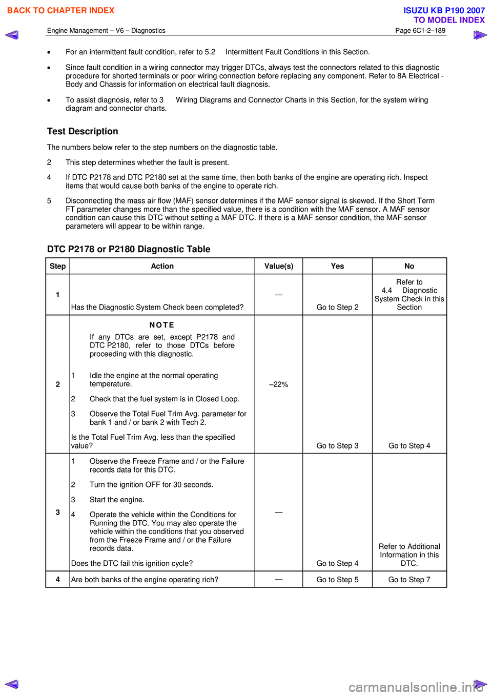
DTC P2178 or P2180 Diagnostic Table
Step Action Value(s) Yes No
1
Has the Diagnostic System Check been completed? —
Go to Step 2 Refer to
4.4 Diagnostic
System Check in this Section
2 NOTE
If any DTCs are set, except P2178 and
DTC P2180, refer to those DTCs before
proceeding with this diagnostic.
1 Idle the engine at the normal operating temperature.
2 Check that the fuel system is in Closed Loop.
3 Observe the Total Fuel Trim Avg. parameter for bank 1 and / or bank 2 with Tech 2.
Is the Total Fuel Trim Avg. less than the specified
value? –22%
Go to Step 3 Go to Step 4
3 1 Observe the Freeze Frame and / or the Failure
records data for this DTC.
2 Turn the ignition OFF for 30 seconds.
3 Start the engine.
4 Operate the vehicle within the Conditions for Running the DTC. You may also operate the
vehicle within the conditions that you observed
from the Freeze Frame and / or the Failure
records data.
Does the DTC fail this ignition cycle? —
Go to Step 4 Refer to Additional
Information in this DTC.
4 Are both banks of the engine operating rich? —
Go to Step 5 Go to Step 7
BACK TO CHAPTER INDEX
TO MODEL INDEX
ISUZU KB P190 2007
Page 3470 of 6020
Engine Management – V6 – Diagnostics Page 6C1-2–192
Additional Information
• A fuel delivery condition causes this DTC to set. Thoroughly inspect all items that could cause a rich condition.
• For an intermittent fault condition, refer to 5.2 Intermittent Fault Conditions in this Section.
• Since fault condition in a wiring connector may trigger DTCs, always test the connectors related to this diagnostic
procedure for shorted terminals or poor wiring connection before replacing any component. Refer to 8A Electrical -
Body and Chassis for information on electrical fault diagnosis.
• To assist diagnosis, refer to 3 W iring Diagrams and Connector Charts in this Section, for the system wiring
diagram and connector charts.
Test Description
The numbers below refer to the step numbers on the diagnostic table.
2 This step determines if there is a current condition.
4 If DTC P2187 and P2189 are set at the same time, this indicates that both banks of the engine are operating lean. Inspect for items that would cause both banks of the engine to operate lean.
5 Disconnecting the mass air flow (MAF) sensor determines if the MAF sensor signal is skewed. If the Short Term FT parameter changes more than the specified value, there is a condition with the MAF sensor. A MAF sensor
condition can cause this DTC without setting a MAF DTC. If there is a MAF sensor condition, the MAF sensor
parameters will appear to be within range.
6 A vacuum leak causes DTC P2187 and P2189 to set at the same time. Inspect all areas of the engine for a vacuum leak. Also inspect the positive crankcase ventilation (PCV) valve for being the correct one for this
application. Make sure that the engine oil fill cap is in place and that it is tight. Verify that the engine oil dip stick is
fully seated.
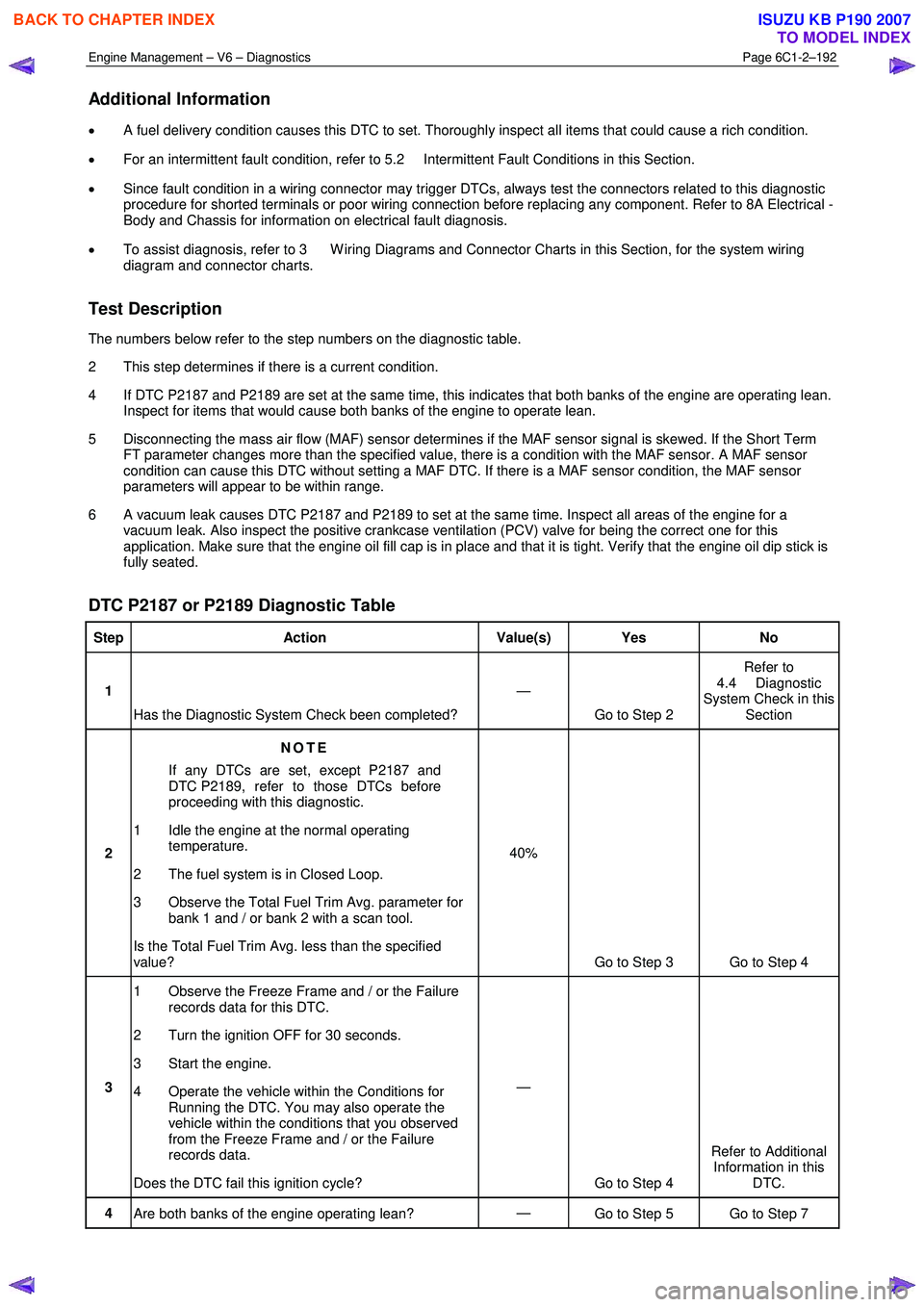
DTC P2187 or P2189 Diagnostic Table
Step Action Value(s) Yes No
1
Has the Diagnostic System Check been completed? —
Go to Step 2 Refer to
4.4 Diagnostic
System Check in this Section
2 NOTE
If any DTCs are set, except P2187 and
DTC P2189, refer to those DTCs before
proceeding with this diagnostic.
1 Idle the engine at the normal operating temperature.
2 The fuel system is in Closed Loop.
3 Observe the Total Fuel Trim Avg. parameter for bank 1 and / or bank 2 with a scan tool.
Is the Total Fuel Trim Avg. less than the specified
value? 40%
Go to Step 3 Go to Step 4
3 1 Observe the Freeze Frame and / or the Failure
records data for this DTC.
2 Turn the ignition OFF for 30 seconds.
3 Start the engine.
4 Operate the vehicle within the Conditions for Running the DTC. You may also operate the
vehicle within the conditions that you observed
from the Freeze Frame and / or the Failure
records data.
Does the DTC fail this ignition cycle? —
Go to Step 4 Refer to Additional
Information in this DTC.
4 Are both banks of the engine operating lean? —
Go to Step 5 Go to Step 7
BACK TO CHAPTER INDEX
TO MODEL INDEX
ISUZU KB P190 2007