Page 5751 of 6020

RESTRAINT CONTROL SYSTEM 9A1-69
DTC Will Clear When
The malfunction is no longer occurring and the ignition
is turned to “LOCK”.
DTC Chart Test Description
Number(s) below refer to step number(s) on the
diagnostic chart:
4. This test determines whether the SRS control unit is malfunctioning
5. This test determines whether the malfunction is in the “SRS W arning Lamp” circuit.
7. This test determines whether the SRS control unit is malfunctioning
8. This test determines whether the malfunction is in
the “SRS W arning Lamp” circuit.
9. This test determines whether the malfunction is in the power supply circuit of the "SRS" warning lamp.
Diagnostic Aids
The warning lamp turns “ON" without relation SRS
control unit, and turn the warning lamp “OFF" due to
electric current to SRS control unit.
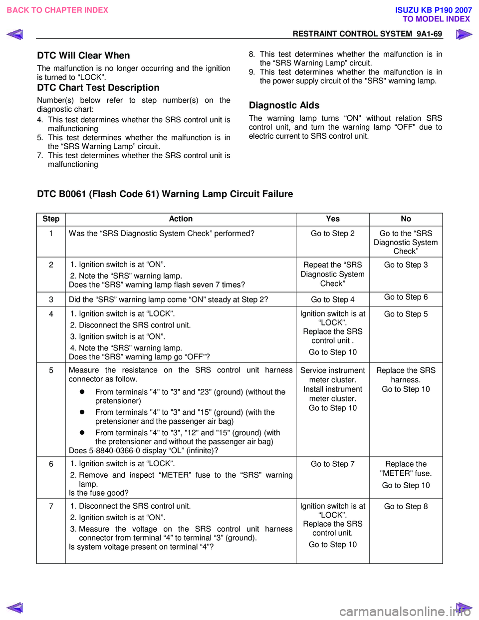
DTC B0061 (Flash Code 61) Warning Lamp Circuit Failure
Step Action Yes No
1 W as the “SRS Diagnostic System Check” performed? Go to Step 2 Go to the “SRS
Diagnostic System Check”
2
1. Ignition switch is at “ON”.
2. Note the “SRS” warning lamp.
Does the “SRS” warning lamp flash seven 7 times? Repeat the “SRS
Diagnostic System Check” Go to Step 3
3 Did the “SRS” warning lamp come “ON” steady at Step 2? Go to Step 4
Go to Step 6
4
1. Ignition switch is at “LOCK”.
2. Disconnect the SRS control unit.
3. Ignition switch is at “ON”.
4. Note the “SRS” warning lamp.
Does the “SRS” warning lamp go “OFF”? Ignition switch is at
“LOCK”.
Replace the SRS control unit .
Go to Step 10 Go to Step 5
5
Measure the resistance on the SRS control unit harness
connector as follow.
�z From terminals "4" to "3" and "23" (ground) (without the
pretensioner)
�z From terminals "4" to "3" and "15" (ground) (with the
pretensioner and the passenger air bag)
�z From terminals "4" to "3", "12" and "15" (ground) (with
the pretensioner and without the passenger air bag)
Does 5-8840-0366-0 display “OL” (infinite)? Service instrument
meter cluster.
Install instrument meter cluster.
Go to Step 10 Replace the SRS
harness.
Go to Step 10
6
1. Ignition switch is at “LOCK”.
2. Remove and inspect “METER” fuse to the “SRS” warning lamp.
Is the fuse good? Go to Step 7 Replace the
"METER" fuse.
Go to Step 10
7 1. Disconnect the SRS control unit.
2. Ignition switch is at “ON”.
3. Measure the voltage on the SRS control unit harness connector from terminal “4” to terminal “3” (ground).
Is system voltage present on terminal “4”? Ignition switch is at
“LOCK”.
Replace the SRS control unit.
Go to Step 10
Go to Step 8
BACK TO CHAPTER INDEX
TO MODEL INDEX
ISUZU KB P190 2007
Page 5752 of 6020

9A1-70 RESTRAINT CONTROL SYSTEM
Step Action Yes No
8 1. Ignition switch is at “LOCK”.
2. Measure the resistance from the instrument meter cluster harness connector "SRS" warning lamp circuit terminal to the
SRS control unit harness connector terminal “4”.
Is the resistance 5.0 ohms or less? Go to Step 9 Replace the SRS
harness.
Go to Step 10
9 1. Disconnect the instrument meter cluster harness connector.
2. Measure the resistance from the "METER" fuse to the instrument meter cluster harness connector "SRS" warning
lamp power supply circuit terminal.
Is the resistance 5.0 ohms or less? Service instrument
meter cluster.
Install instrument meter cluster.
Go to Step 10 Replace the "SRS"
warning lamp power supply
circuit harness.
Go to Step 10
10 1. Reconnect all components and ensure all components are
properly mounted.
2. Clear the diagnostic trouble codes.
Is this step finished? Go to the “SRS
Diagnostic System Check” ―
BACK TO CHAPTER INDEX
TO MODEL INDEX
ISUZU KB P190 2007
Page 5754 of 6020
9A1-72 RESTRAINT CONTROL SYSTEM
DTC B0062 (Flash Code 62) Battery Voltage Too High
Step Action Yes No
1 W as the “SRS Diagnostic System Check” performed? Go to Step 2 Go to the “SRS
Diagnostic System Check”
2 1. Ignition switch is at “LOCK”.
2. Disconnect the SRS control unit.
3. Ignition switch “ON”.
4. Measure voltage on SRS control unit harness connector from terminal “1” to terminal “3” (ground).
Is voltage on terminal “1” below 16.5V? Ignition switch is at
“LOCK”.
Replace the SRS control unit.
Go to Step 3 Inspect the
Charging System. Refer to the
"Engine Electrical" section.
Go to Step 3
3 1. Reconnect all the components and ensure all components
are properly mounted.
2. Clear diagnostic trouble codes.
Is this step finished? Go to the “SRS
Diagnostic system Check” ―
BACK TO CHAPTER INDEX
TO MODEL INDEX
ISUZU KB P190 2007
Page 5756 of 6020

9A1-74 RESTRAINT CONTROL SYSTEM
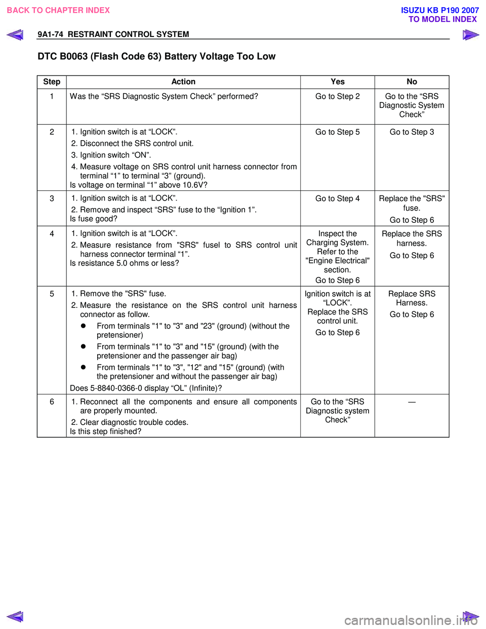
DTC B0063 (Flash Code 63) Battery Voltage Too Low
Step Action Yes No
1 W as the “SRS Diagnostic System Check” performed? Go to Step 2 Go to the “SRS
Diagnostic System Check”
2 1. Ignition switch is at “LOCK”.
2. Disconnect the SRS control unit.
3. Ignition switch “ON”.
4. Measure voltage on SRS control unit harness connector from terminal “1” to terminal “3” (ground).
Is voltage on terminal “1” above 10.6V? Go to Step 5 Go to Step 3
3
1. Ignition switch is at “LOCK”.
2. Remove and inspect “SRS” fuse to the “Ignition 1”.
Is fuse good? Go to Step 4 Replace the "SRS"
fuse.
Go to Step 6
4
1. Ignition switch is at “LOCK”.
2. Measure resistance from "SRS" fusel to SRS control unit
harness connector terminal “1”.
Is resistance 5.0 ohms or less? Inspect the
Charging System. Refer to the
"Engine Electrical" section.
Go to Step 6 Replace the SRS
harness.
Go to Step 6
5
1. Remove the "SRS" fuse.
2. Measure the resistance on the SRS control unit harness connector as follow.
�z From terminals "1" to "3" and "23" (ground) (without the
pretensioner)
�z From terminals "1" to "3" and "15" (ground) (with the
pretensioner and the passenger air bag)
�z From terminals "1" to "3", "12" and "15" (ground) (with
the pretensioner and without the passenger air bag)
Does 5-8840-0366-0 display “OL” (Infinite)? Ignition switch is at
“LOCK”.
Replace the SRS control unit.
Go to Step 6 Replace SRS
Harness.
Go to Step 6
6 1. Reconnect all the components and ensure all components
are properly mounted.
2. Clear diagnostic trouble codes.
Is this step finished? Go to the “SRS
Diagnostic system Check” ―
BACK TO CHAPTER INDEX
TO MODEL INDEX
ISUZU KB P190 2007
Page 5767 of 6020
CAB 10-9
FRONT DOOR ASSEMBLY
REMOVAL AND INSTALLATION
This illustration is based on RHD model
Removal Steps
▲ 1 . Door harness
▲ 2. Check arm screw
▲ 3. Lower hinge bolt
4. Upper hinge bolt
5. Door assembly
Installation Steps
5. Door assembly
4. Upper hinge bolt
▲ 3. Lower hinge bolt
▲ 2. Check arm screw
1. Door harness
RUW 5A0SH002 101
Important Operations - Removal
1. Door Harness
Remove the harness bracket and disconnect the doo
r
harness connectors.
BACK TO CHAPTER INDEX TO MODEL INDEX
ISUZU KB P190 2007
Page 5769 of 6020
CAB 10-11
DISASSEMBLY
This illustration is based on RHD model
RTW 4A0LF000701
Disassembly Steps
▲ 1 . Switch bezel/W indow regulator handle
▲ 2. Power window switch
▲ 3. Bezel
▲ 4. Door mirror cover
▲ 5. Door trim panel
▲ 6. Tweeter (Required Option)
▲ 7. Door mirror assembly
▲ 8. Outer waste seal
▲ 9. Bracket
▲ 10. Speaker assembly
▲ 11 . W aterproof sheet
▲ 12. Inside lever
▲ 13. W indow glass
▲ 14. W indow regulator/Power window
regulator
▲
15. Glass run
▲ 16. Glass run rear channel / Glass ran rear
channel with Door lock control or Anti
theft (European Countries)
▲ 17. Door lock assembly/Door lock assembly
with super lock
▲ 18. Outside handle protector (EUROPE)
▲ 19. Outside handle
▲ 20. Door lock cylinder protector (EUROPE)
▲ 21. Door lock cylinder / Door lock cylinder
with door lock switch (European
Countries)
22. Door harness assembly
23. Anti rattler
BACK TO CHAPTER INDEX TO MODEL INDEX
ISUZU KB P190 2007
Page 5771 of 6020
CAB 10-13
• Remove the 2 screws and pull out the trim panel at the 8
clip positions (W indow regulator handle type).
RTW 3A0SH00070 1
6. Tweeter (Required option)
• Disconnect the tweeter harness connector and remove
the 3 screws.
7. Door Mirror Assembly
• Remove 3 fixing bolts and then remove the connector.
8. Outer Waste Seal
9. Bracket
10. Speaker Assembly • Remove the fixing screw and then remove the
connector.
11. Waterproof Sheet • Take care not to damage the sheet when peeling it off.
12. Inside Lever • Disconnect the door lock cables.
BACK TO CHAPTER INDEX
TO MODEL INDEX
ISUZU KB P190 2007
Page 5772 of 6020

10-14 CAB
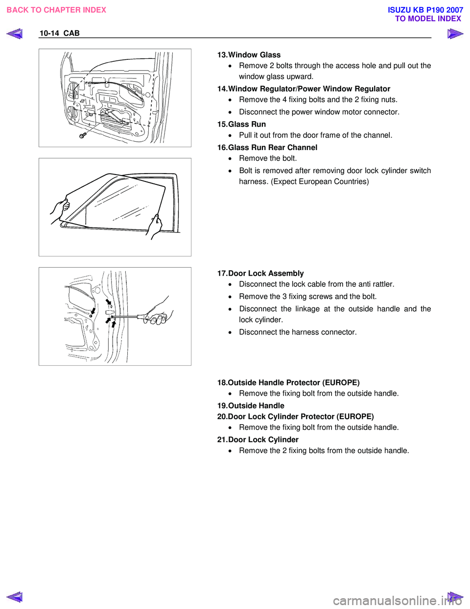
13. Window Glass
• Remove 2 bolts through the access hole and pull out the
window glass upward.
14. Window Regulator/Power Window Regulator • Remove the 4 fixing bolts and the 2 fixing nuts.
• Disconnect the power window motor connector.
15. Glass Run • Pull it out from the door frame of the channel.
16. Glass Run Rear Channel • Remove the bolt.
• Bolt is removed after removing door lock cylinder switch
harness. (Expect European Countries)
17. Door Lock Assembly
• Disconnect the lock cable from the anti rattler.
• Remove the 3 fixing screws and the bolt.
• Disconnect the linkage at the outside handle and the
lock cylinder.
• Disconnect the harness connector.
18.Outside Handle Protector (EUROPE)
• Remove the fixing bolt from the outside handle.
19. Outside Handle
20.Door Lock Cylinder Protector (EUROPE) • Remove the fixing bolt from the outside handle.
21. Door Lock Cylinder • Remove the 2 fixing bolts from the outside handle.
BACK TO CHAPTER INDEX TO MODEL INDEX
ISUZU KB P190 2007