2007 ISUZU KB P190 transfer case
[x] Cancel search: transfer casePage 4933 of 6020
TRANSFER CONTROL SYSTEM 7D1-59
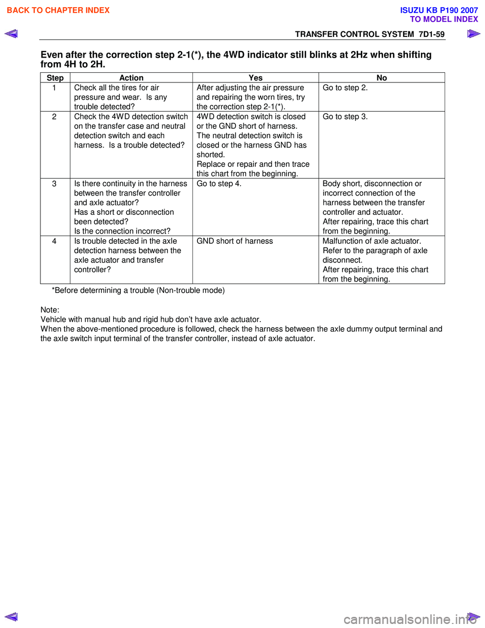
Even after the correction step 2-1(*), the 4WD indicator still blinks at 2Hz when shifting
from 4H to 2H.
Step Action Yes No
1 Check all the tires for air
pressure and wear. Is any
trouble detected? After adjusting the air pressure
and repairing the worn tires, try
the correction step 2-1(*). Go to step 2.
2
Check the 4W D detection switch
on the transfer case and neutral
detection switch and each
harness. Is a trouble detected? 4W D detection switch is closed
or the GND short of harness.
The neutral detection switch is
closed or the harness GND has
shorted.
Replace or repair and then trace
this chart from the beginning. Go to step 3.
3
Is there continuity in the harness
between the transfer controller
and axle actuator?
Has a short or disconnection
been detected?
Is the connection incorrect? Go to step 4.
Body short, disconnection or
incorrect connection of the
harness between the transfer
controller and actuator.
After repairing, trace this chart
from the beginning.
4 Is trouble detected in the axle
detection harness between the
axle actuator and transfer
controller? GND short of harness
Malfunction of axle actuator.
Refer to the paragraph of axle
disconnect.
After repairing, trace this chart
from the beginning.
*Before determining a trouble (Non-trouble mode)
Note:
Vehicle with manual hub and rigid hub don’t have axle actuator.
W hen the above-mentioned procedure is followed, check the harness between the axle dummy output terminal and
the axle switch input terminal of the transfer controller, instead of axle actuator.
BACK TO CHAPTER INDEX
TO MODEL INDEX
ISUZU KB P190 2007
Page 4934 of 6020
7D1-60 TRANSFER CONTROL SYSTEM
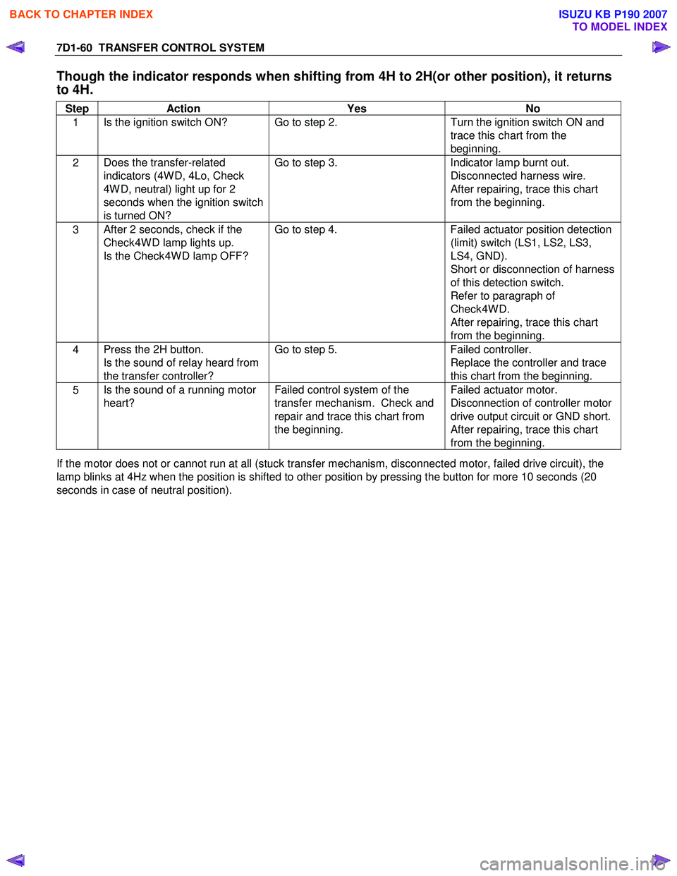
Though the indicator responds when shifting from 4H to 2H(or other position), it returns
to 4H.
Step Action Yes No
1 Is the ignition switch ON? Go to step 2.
Turn the ignition switch ON and
trace this chart from the
beginning.
2 Does the transfer-related
indicators (4W D, 4Lo, Check
4W D, neutral) light up for 2
seconds when the ignition switch
is turned ON? Go to step 3.
Indicator lamp burnt out.
Disconnected harness wire.
After repairing, trace this chart
from the beginning.
3 After 2 seconds, check if the
Check4W D lamp lights up.
Is the Check4W D lamp OFF? Go to step 4.
Failed actuator position detection
(limit) switch (LS1, LS2, LS3,
LS4, GND).
Short or disconnection of harness
of this detection switch.
Refer to paragraph of
Check4W D.
After repairing, trace this chart
from the beginning.
4 Press the 2H button.
Is the sound of relay heard from
the transfer controller? Go to step 5.
Failed controller.
Replace the controller and trace
this chart from the beginning.
5 Is the sound of a running motor
heart? Failed control system of the
transfer mechanism. Check and
repair and trace this chart from
the beginning. Failed actuator motor.
Disconnection of controller motor
drive output circuit or GND short.
After repairing, trace this chart
from the beginning.
If the motor does not or cannot run at all (stuck transfer mechanism, disconnected motor, failed drive circuit), the
lamp blinks at 4Hz when the position is shifted to other position by pressing the button for more 10 seconds (20
seconds in case of neutral position).
BACK TO CHAPTER INDEX
TO MODEL INDEX
ISUZU KB P190 2007
Page 4935 of 6020
TRANSFER CONTROL SYSTEM 7D1-61
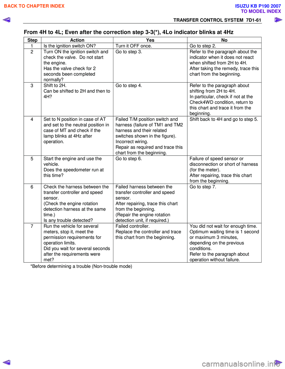
From 4H to 4L; Even after the correction step 3-3(*), 4Lo indicator blinks at 4Hz
Step Action Yes No
1 Is the ignition switch ON? Turn it OFF once.
Go to step 2.
2 Turn ON the ignition switch and
check the valve. Do not start
the engine.
Has the valve check for 2
seconds been completed
normally? Go to step 3.
Refer to the paragraph about the
indicator when it does not react
when shifted from 2H to 4H.
After taking the remedy, trace this
chart from the beginning.
3 Shift to 2H.
Can be shifted to 2H and then to
4H? Go to step 4.
Refer to the paragraph about
shifting from 2H to 4H.
In particular, check if not at the
Check4W D condition, return to
this chart and trace it from the
beginning.
4 Set to N position in case of AT
and set to the neutral position in
case of MT and check if the
lamp blinks at 4Hz after
operation.
Failed T/M position switch and
harness (failure of TM1 and TM2
harness and their related
switches shown in the figure).
Incorrect wiring.
Repair as required and trace this
chart from the beginning. Shift back to 4H and go to step 5.
5
Start the engine and use the
vehicle.
Does the speedometer run at
this time? Go to step 6.
Failure of speed sensor or
disconnection or short of harness
(for the meter).
After repairing, trace this chart
from the beginning.
6 Check the harness between the
transfer controller and speed
sensor.
(Check the engine rotation
detection harness at the same
time.)
Is any trouble detected? Failed harness between the
transfer controller and speed
sensor.
After repairing, trace this chart
from the beginning.
(Repair the engine rotation
detection unit, if required.) Go to step 7.
7
Run the vehicle for several
meters, stop it, meet the
permission requirements for
operation limits.
Did you wait for several seconds
after the requirements were
met? Failed controller.
Replace the controller and trace
this chart from the beginning. You did not wait for enough time.
Optimum waiting time is 1 second
or maximum 3 minutes,
depending on the previous
conditions.
Refer to the paragraph about
operation without failure.
*Before determining a trouble (Non-trouble mode)
BACK TO CHAPTER INDEX
TO MODEL INDEX
ISUZU KB P190 2007
Page 4936 of 6020
7D1-62 TRANSFER CONTROL SYSTEM
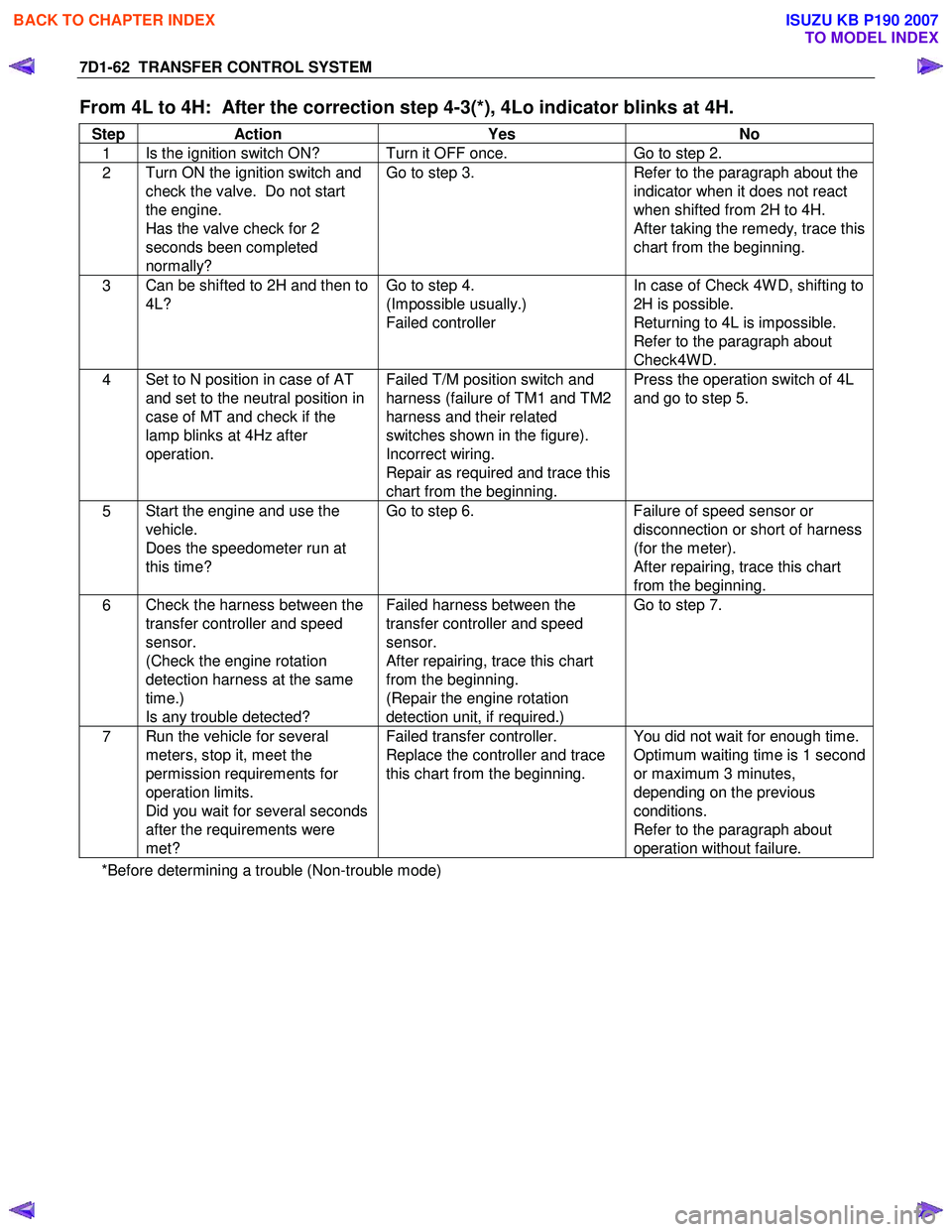
From 4L to 4H: After the correction step 4-3(*), 4Lo indicator blinks at 4H.
Step Action Yes No
1 Is the ignition switch ON? Turn it OFF once.
Go to step 2.
2 Turn ON the ignition switch and
check the valve. Do not start
the engine.
Has the valve check for 2
seconds been completed
normally? Go to step 3.
Refer to the paragraph about the
indicator when it does not react
when shifted from 2H to 4H.
After taking the remedy, trace this
chart from the beginning.
3 Can be shifted to 2H and then to
4L? Go to step 4.
(Impossible usually.)
Failed controller In case of Check 4W D, shifting to
2H is possible.
Returning to 4L is impossible.
Refer to the paragraph about
Check4W D.
4 Set to N position in case of AT
and set to the neutral position in
case of MT and check if the
lamp blinks at 4Hz after
operation.
Failed T/M position switch and
harness (failure of TM1 and TM2
harness and their related
switches shown in the figure).
Incorrect wiring.
Repair as required and trace this
chart from the beginning. Press the operation switch of 4L
and go to step 5.
5 Start the engine and use the
vehicle.
Does the speedometer run at
this time? Go to step 6.
Failure of speed sensor or
disconnection or short of harness
(for the meter).
After repairing, trace this chart
from the beginning.
6 Check the harness between the
transfer controller and speed
sensor.
(Check the engine rotation
detection harness at the same
time.)
Is any trouble detected? Failed harness between the
transfer controller and speed
sensor.
After repairing, trace this chart
from the beginning.
(Repair the engine rotation
detection unit, if required.) Go to step 7.
7
Run the vehicle for several
meters, stop it, meet the
permission requirements for
operation limits.
Did you wait for several seconds
after the requirements were
met? Failed transfer controller.
Replace the controller and trace
this chart from the beginning. You did not wait for enough time.
Optimum waiting time is 1 second
or maximum 3 minutes,
depending on the previous
conditions.
Refer to the paragraph about
operation without failure.
*Before determining a trouble (Non-trouble mode)
BACK TO CHAPTER INDEX
TO MODEL INDEX
ISUZU KB P190 2007
Page 4937 of 6020
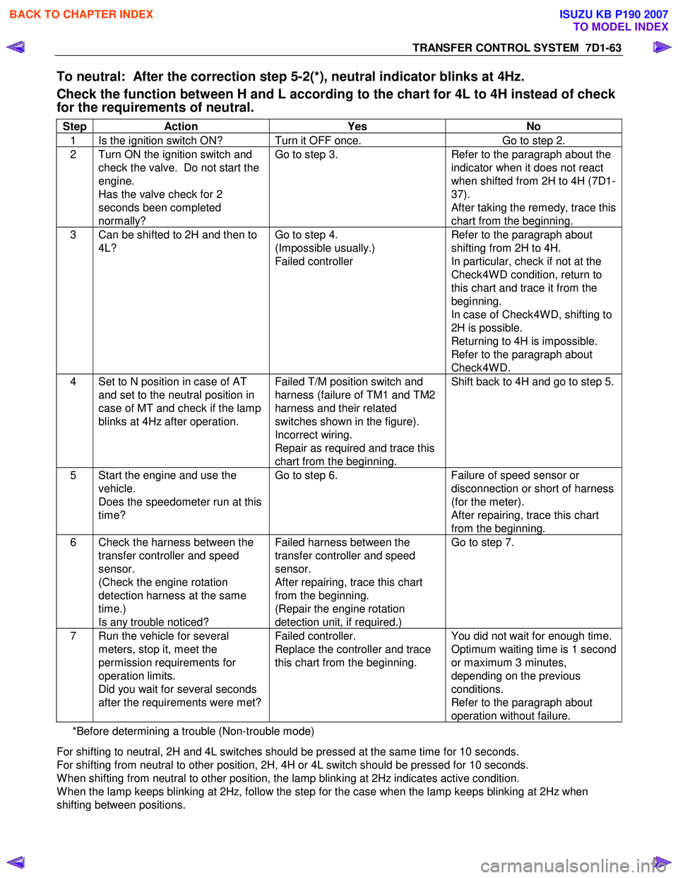
TRANSFER CONTROL SYSTEM 7D1-63
To neutral: After the correction step 5-2(*), neutral indicator blinks at 4Hz.
Check the function between H and L according to the chart for 4L to 4H instead of check
for the requirements of neutral.
Step Action Yes No
1 Is the ignition switch ON? Turn it OFF once. Go to step 2.
2 Turn ON the ignition switch and
check the valve. Do not start the
engine.
Has the valve check for 2
seconds been completed
normally? Go to step 3.
Refer to the paragraph about the
indicator when it does not react
when shifted from 2H to 4H (7D1-
37).
After taking the remedy, trace this
chart from the beginning.
3 Can be shifted to 2H and then to 4L? Go to step 4.
(Impossible usually.)
Failed controller Refer to the paragraph about
shifting from 2H to 4H.
In particular, check if not at the
Check4W D condition, return to
this chart and trace it from the
beginning.
In case of Check4W D, shifting to
2H is possible.
Returning to 4H is impossible.
Refer to the paragraph about
Check4W D.
4 Set to N position in case of AT and set to the neutral position in
case of MT and check if the lamp
blinks at 4Hz after operation. Failed T/M position switch and
harness (failure of TM1 and TM2
harness and their related
switches shown in the figure).
Incorrect wiring.
Repair as required and trace this
chart from the beginning. Shift back to 4H and go to step 5.
5 Start the engine and use the
vehicle.
Does the speedometer run at this
time? Go to step 6.
Failure of speed sensor or
disconnection or short of harness
(for the meter).
After repairing, trace this chart
from the beginning.
6 Check the harness between the transfer controller and speed
sensor.
(Check the engine rotation
detection harness at the same
time.)
Is any trouble noticed? Failed harness between the
transfer controller and speed
sensor.
After repairing, trace this chart
from the beginning.
(Repair the engine rotation
detection unit, if required.) Go to step 7.
7 Run the vehicle for several
meters, stop it, meet the
permission requirements for
operation limits.
Did you wait for several seconds
after the requirements were met? Failed controller.
Replace the controller and trace
this chart from the beginning. You did not wait for enough time.
Optimum waiting time is 1 second
or maximum 3 minutes,
depending on the previous
conditions.
Refer to the paragraph about
operation without failure.
*Before determining a trouble (Non-trouble mode)
For shifting to neutral, 2H and 4L switches should be pressed at the same time for 10 seconds.
For shifting from neutral to other position, 2H, 4H or 4L switch should be pressed for 10 seconds.
W hen shifting from neutral to other position, the lamp blinking at 2Hz indicates active condition.
W hen the lamp keeps blinking at 2Hz, follow the step for the case when the lamp keeps blinking at 2Hz when
shifting between positions.
BACK TO CHAPTER INDEX
TO MODEL INDEX
ISUZU KB P190 2007
Page 4941 of 6020
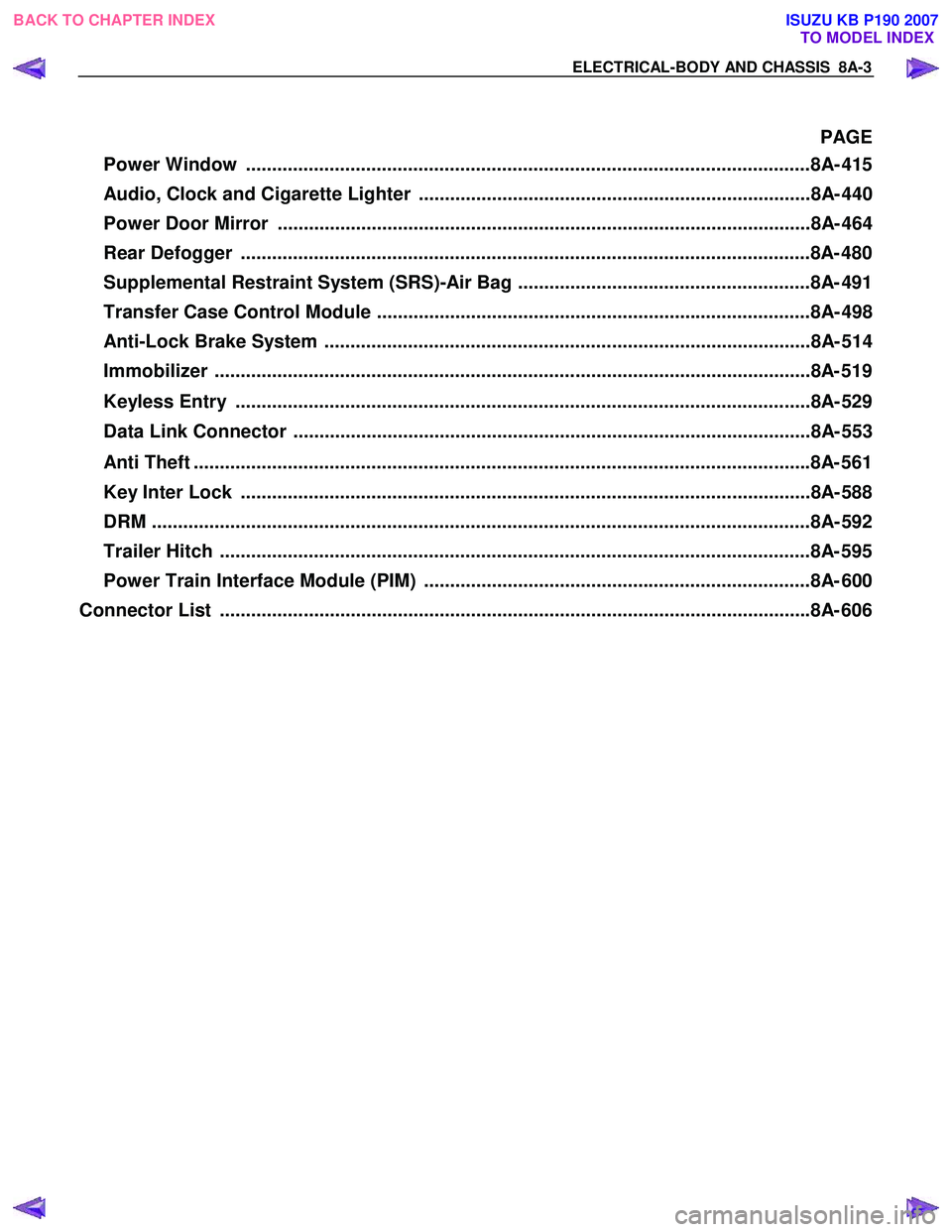
ELECTRICAL-BODY AND CHASSIS 8A-3
PAGE
Power Window ............................................................................................................8A- 41 5
Audio, Clock and Cigarette Lighter ...........................................................................8A- 440
Power Door Mirror ......................................................................................................8A- 464
Rear Defogger .............................................................................................................8A- 480
Supplemental Restraint System (SRS)-Air Bag ........................................................8A- 491
Transfer Case Control Module ...................................................................................8A- 498
Anti-Lock Brake System .............................................................................................8A- 514
Immobilizer ..................................................................................................................8 A- 519
Keyless Entry ..............................................................................................................8A- 529
Data Link Connector ...................................................................................................8A- 553
Anti Theft ..................................................................................................................... .8A- 561
Key Inter Lock .............................................................................................................8A- 588
DRM ........................................................................................................................... ...8A- 592
Trailer Hitch ................................................................................................................. 8A- 595
Power Train Interface Module (PIM) ..........................................................................8A- 600
Connector List ................................................................................................................ .8A- 606
BACK TO CHAPTER INDEX
TO MODEL INDEX
ISUZU KB P190 2007
Page 4950 of 6020
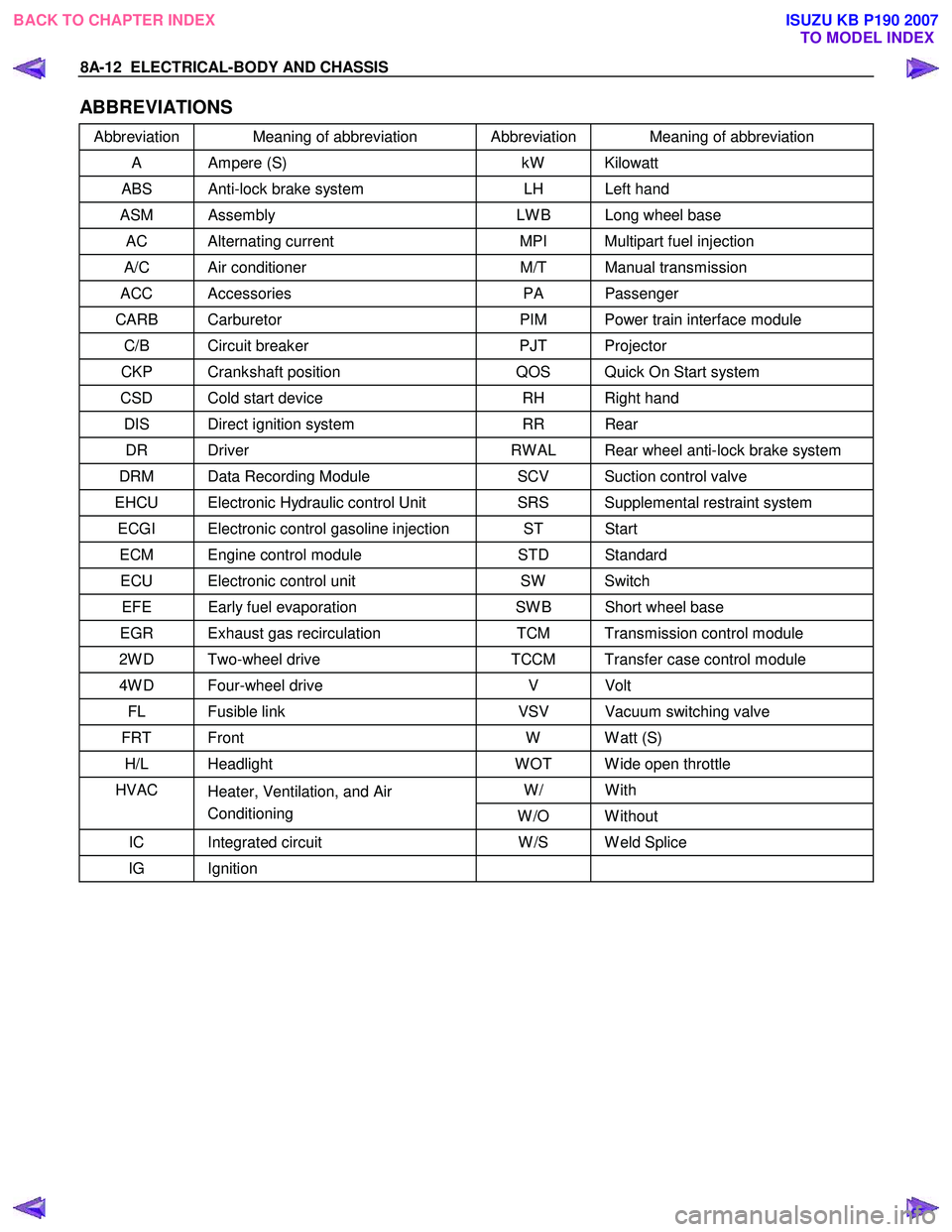
8A-12 ELECTRICAL-BODY AND CHASSIS
ABBREVIATIONS
Abbreviation Meaning of abbreviation Abbreviation Meaning of abbreviation
A Ampere (S) kW Kilowatt
ABS Anti-lock brake system LH Left hand
ASM Assembly LW B Long wheel base
AC Alternating current MPI Multipart fuel injection
A/C Air conditioner M/T Manual transmission
ACC Accessories PA Passenger
CARB Carburetor PIM Power train interface module
C/B Circuit breaker PJT Projector
CKP Crankshaft position QOS Quick On Start system
CSD Cold start device RH Right hand
DIS Direct ignition system RR Rear
DR Driver RW AL Rear wheel anti-lock brake system
DRM Data Recording Module SCV Suction control valve
EHCU Electronic Hydraulic control Unit SRS Supplemental restraint system
ECGI Electronic control gasoline injection ST Start
ECM Engine control module STD Standard
ECU Electronic control unit SW Switch
EFE Early fuel evaporation SW B Short wheel base
EGR Exhaust gas recirculation TCM Transmission control module
2W D Two-wheel drive TCCM Transfer case control module
4W D Four-wheel drive V Volt
FL Fusible link VSV Vacuum switching valve
FRT Front W W att (S)
H/L Headlight W OT W ide open throttle
W/ With HVAC
Heater, Ventilation, and Air
Conditioning W /O W ithout
IC Integrated circuit W /S W eld Splice
IG Ignition
BACK TO CHAPTER INDEX
TO MODEL INDEXISUZU KB P190 2007
Page 5436 of 6020
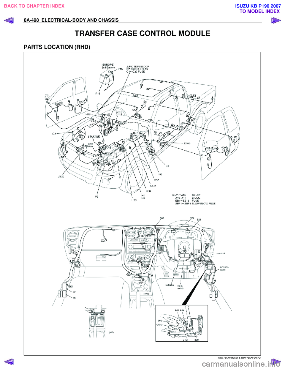
8A-498 ELECTRICAL-BODY AND CHASSIS
TRANSFER CASE CONTROL MODULE
PARTS LOCATION (RHD)
RTW 78AXF040501 & RTW 78AXF046701
BACK TO CHAPTER INDEX TO MODEL INDEXISUZU KB P190 2007