2007 ISUZU KB P190 check engine
[x] Cancel search: check enginePage 1027 of 6020
6D – 26 ENGINE ELECTRICAL
INSPECTION AND REPAIR
Make the necessary adjustments, repairs, and part replacement if excessive wear or damage is discovered during
inspection.
ARMATURE
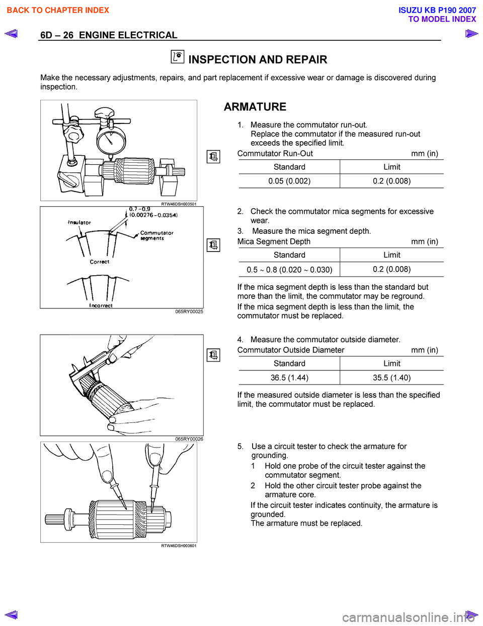
1. Measure the commutator run-out. Replace the commutator if the measured run-out
exceeds the specified limit.
Commutator Run-Out mm (in)
Standard Limit
0.05 (0.002) 0.2 (0.008)
RTW46DSH003501
2. Check the commutator mica segments for excessive
wear.
3. Measure the mica segment depth.
Mica Segment Depth mm (in)
Standard Limit
0.5 ∼ 0.8 (0.020 ∼ 0.030) 0.2 (0.008)
065RY00025
If the mica segment depth is less than the standard but
more than the limit, the commutator may be reground.
If the mica segment depth is less than the limit, the
commutator must be replaced.
4. Measure the commutator outside diameter.
Commutator Outside Diameter mm (in)
Standard Limit
36.5 (1.44) 35.5 (1.40)
If the measured outside diameter is less than the specified
limit, the commutator must be replaced.
065RY00026
RTW46DSH003601
5. Use a circuit tester to check the armature for
grounding.
1 Hold one probe of the circuit tester against the commutator segment.
2 Hold the other circuit tester probe against the armature core.
If the circuit tester indicates continuity, the armature is grounded.
The armature must be replaced.
BACK TO CHAPTER INDEX
TO MODEL INDEX
ISUZU KB P190 2007
Page 1028 of 6020
ENGINE ELECTRICAL 6D – 27
RTW46DSH003701
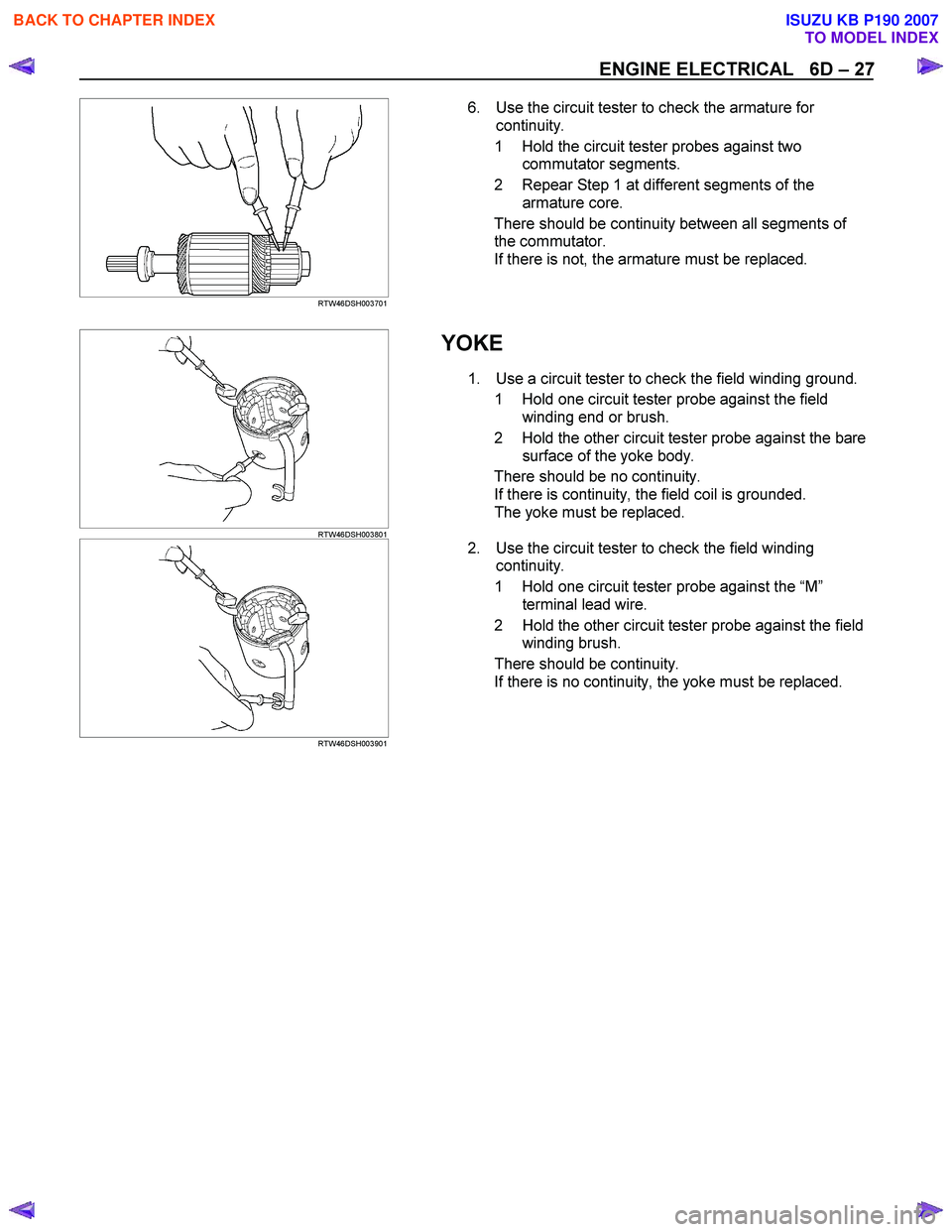
6. Use the circuit tester to check the armature for
continuity.
1 Hold the circuit tester probes against two commutator segments.
2 Repear Step 1 at different segments of the armature core.
There should be continuity between all segments of the commutator.
If there is not, the armature must be replaced.
RTW46DSH003801
YOKE
1. Use a circuit tester to check the field winding ground.
1 Hold one circuit tester probe against the field winding end or brush.
2 Hold the other circuit tester probe against the bare surface of the yoke body.
There should be no continuity. If there is continuity, the field coil is grounded.
The yoke must be replaced.
RTW46DSH003901
2. Use the circuit tester to check the field winding
continuity.
1 Hold one circuit tester probe against the “M ”
terminal lead wire.
2 Hold the other circuit tester probe against the field winding brush.
There should be continuity. If there is no continuity, the yoke must be replaced.
BACK TO CHAPTER INDEX
TO MODEL INDEX
ISUZU KB P190 2007
Page 1029 of 6020
6D – 28 ENGINE ELECTRICAL
BRUSH AND BRUSH HOLDER
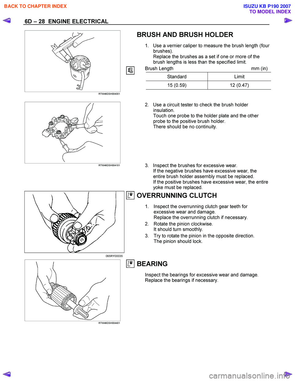
1. Use a vernier caliper to measure the brush length (four
brushes).
Replace the brushes as a set if one or more of the
brush lengths is less than the specified limit.
Brush Length mm (in)
Standard Limit
15 (0.59) 12 (0.47)
RTW46DSH004001
RTW46DSH004101
2. Use a circuit tester to check the brush holder
insulation.
Touch one probe to the holder plate and the other
probe to the positive brush holder.
There should be no continuity.
3. Inspect the brushes for excessive wear. If the negative brushes have excessive wear, the
entire brush holder assembly must be replaced.
If the positive brushes have excessive wear, the entire
yoke must be replaced.
OVERRUNNING CLUTCH
1. Inspect the overrunning clutch gear teeth for excessive wear and damage.
Replace the overrunning clutch if necessary.
2. Rotate the pinion clockwise. It should turn smoothly.
3. Try to rotate the pinion in the opposite direction. The pinion should lock.
065RY00035
RTW46DSH004401
BEARING
Inspect the bearings for excessive wear and damage.
Replace the bearings if necessary.
BACK TO CHAPTER INDEX
TO MODEL INDEX
ISUZU KB P190 2007
Page 1034 of 6020
ENGINE ELECTRICAL 6D – 33
PRE-HEATING SYSTEM
INSPECTION AND REPAIR
Make the necessary adjustments, repairs, and part replacement if excessive wear of damage is discovered during
inspection.
VISUAL CHECK
Check the main fuses and glow indicator for damage.
Replace the part(s) if required.
GLOW RELAY
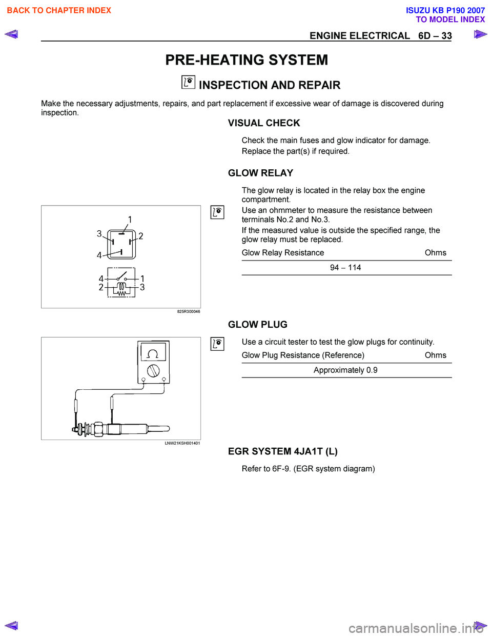
The glow relay is located in the relay box the engine
compartment.
825R300046
Use an ohmmeter to measure the resistance between
terminals No.2 and No.3.
If the measured value is outside the specified range, the
glow relay must be replaced.
Glow Relay Resistance Ohms
94 − 114
GLOW PLUG
LNW21KSH001401
Use a circuit tester to test the glow plugs for continuity.
Glow Plug Resistance (Reference) Ohms
Approximately 0.9
EGR SYSTEM 4JA1T (L)
Refer to 6F-9. (EGR system diagram)
BACK TO CHAPTER INDEX
TO MODEL INDEX
ISUZU KB P190 2007
Page 1035 of 6020
Engine Control System (4JH1) 6E-1
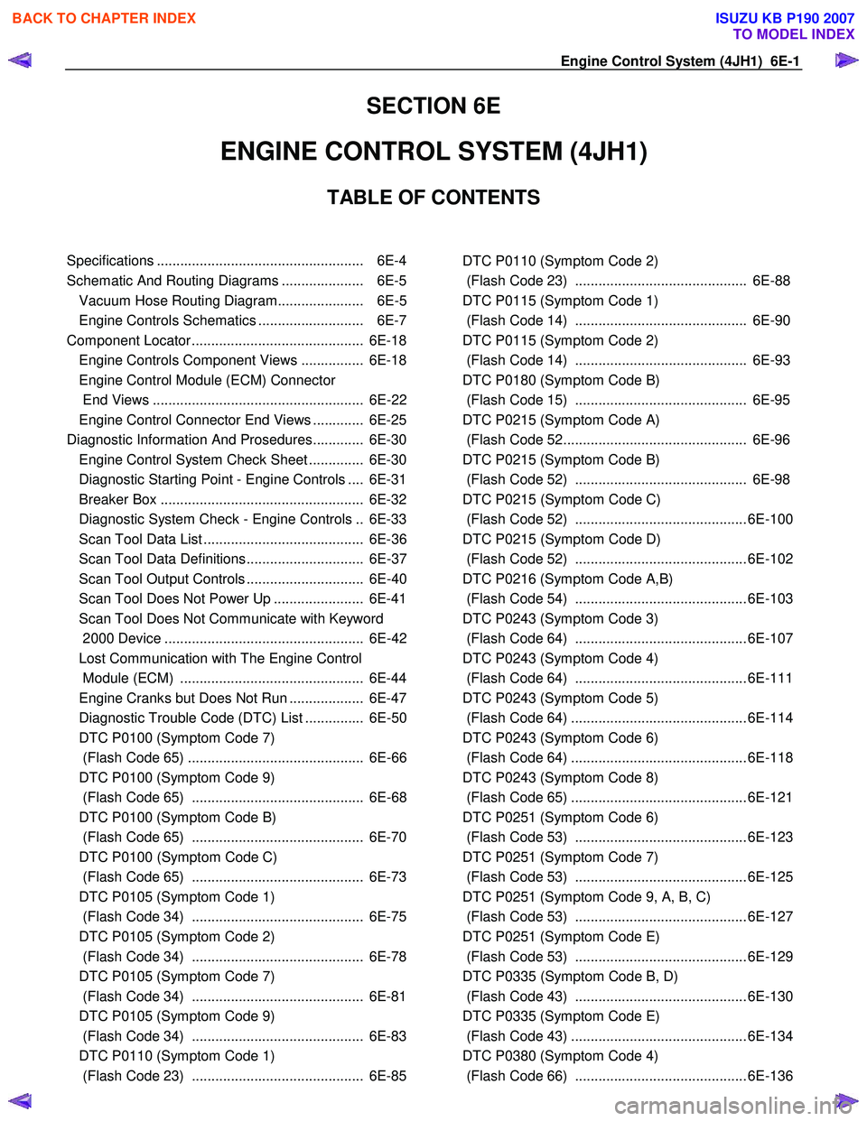
SECTION 6E
ENGINE CONTROL SYSTEM (4JH1)
TABLE OF CONTENTS
Specifications ..................................................... 6E-4
Schematic And Routing Diagrams ..................... 6E-5 Vacuum Hose Routing Diagram...................... 6E-5
Engine Controls Schematics ........................... 6E-7
Component Locator ............................................ 6E-18 Engine Controls Component Views ................ 6E-18
Engine Control Module (ECM) Connector
End Views ...................................................... 6E-22
Engine Control Connector End Views ............. 6E-25
Diagnostic Information And Prosedures............. 6E-30 Engine Control System Check Sheet .............. 6E-30
Diagnostic Starting Point - Engine Controls .... 6E-31
Breaker Box .................................................... 6E-32
Diagnostic System Check - Engine Controls .. 6E-33
Scan Tool Data List ......................................... 6E-36
Scan Tool Data Definitions.............................. 6E-37
Scan Tool Output Controls .............................. 6E-40
Scan Tool Does Not Power Up ....................... 6E-41
Scan Tool Does Not Communicate with Keyword
2000 Device ................................................... 6E-42
Lost Communication with The Engine Control
Module (ECM) ............................................... 6E-44
Engine Cranks but Does Not Run ................... 6E-47
Diagnostic Trouble Code (DTC) List ............... 6E-50
DTC P0100 (Symptom Code 7)
(Flash Code 65) ............................................. 6E-66
DTC P0100 (Symptom Code 9)
(Flash Code 65) ............................................ 6E-68
DTC P0100 (Symptom Code B)
(Flash Code 65) ............................................ 6E-70
DTC P0100 (Symptom Code C)
(Flash Code 65) ............................................ 6E-73
DTC P0105 (Symptom Code 1)
(Flash Code 34) ............................................ 6E-75
DTC P0105 (Symptom Code 2)
(Flash Code 34) ............................................ 6E-78
DTC P0105 (Symptom Code 7)
(Flash Code 34) ............................................ 6E-81
DTC P0105 (Symptom Code 9)
(Flash Code 34) ............................................ 6E-83
DTC P0110 (Symptom Code 1)
(Flash Code 23) ............................................ 6E-85
DTC P0110 (Symptom Code 2)
(Flash Code 23) ............................................ 6E-88
DTC P0115 (Symptom Code 1)
(Flash Code 14) ............................................ 6E-90
DTC P0115 (Symptom Code 2)
(Flash Code 14) ............................................ 6E-93
DTC P0180 (Symptom Code B)
(Flash Code 15) ............................................ 6E-95
DTC P0215 (Symptom Code A)
(Flash Code 52............................................... 6E-96
DTC P0215 (Symptom Code B)
(Flash Code 52) ............................................ 6E-98
DTC P0215 (Symptom Code C)
(Flash Code 52) ............................................ 6E-100
DTC P0215 (Symptom Code D)
(Flash Code 52) ............................................ 6E-102
DTC P0216 (Symptom Code A,B)
(Flash Code 54) ............................................ 6E-103
DTC P0243 (Symptom Code 3)
(Flash Code 64) ............................................ 6E-107
DTC P0243 (Symptom Code 4)
(Flash Code 64) ............................................ 6E-111
DTC P0243 (Symptom Code 5)
(Flash Code 64) ............................................. 6E-114
DTC P0243 (Symptom Code 6)
(Flash Code 64) ............................................. 6E-118
DTC P0243 (Symptom Code 8)
(Flash Code 65) ............................................. 6E-121
DTC P0251 (Symptom Code 6)
(Flash Code 53) ............................................ 6E-123
DTC P0251 (Symptom Code 7)
(Flash Code 53) ............................................ 6E-125
DTC P0251 (Symptom Code 9, A, B, C)
(Flash Code 53) ............................................ 6E-127
DTC P0251 (Symptom Code E)
(Flash Code 53) ............................................ 6E-129
DTC P0335 (Symptom Code B, D)
(Flash Code 43) ............................................ 6E-130
DTC P0335 (Symptom Code E)
(Flash Code 43) ............................................. 6E-134
DTC P0380 (Symptom Code 4)
(Flash Code 66) ............................................ 6E-136
BACK TO CHAPTER INDEX
TO MODEL INDEX
ISUZU KB P190 2007
Page 1036 of 6020
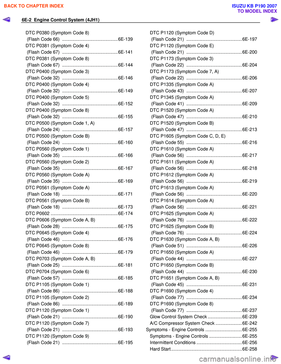
6E-2 Engine Control System (4JH1)
DTC P0380 (Symptom Code 8)
(Flash Code 66) ............................................6E-139
DTC P0381 (Symptom Code 4)
(Flash Code 67) ............................................6E-141
DTC P0381 (Symptom Code 8)
(Flash Code 67) ............................................6E-144
DTC P0400 (Symptom Code 3)
(Flash Code 32) ............................................6E-146
DTC P0400 (Symptom Code 4)
(Flash Code 32) ............................................6E-149
DTC P0400 (Symptom Code 5)
(Flash Code 32) ............................................6E-152
DTC P0400 (Symptom Code 8)
(Flash Code 32) ............................................6E-155
DTC P0500 (Symptom Code 1, A)
(Flash Code 24) ............................................6E-157
DTC P0500 (Symptom Code B)
(Flash Code 24) ............................................6E-160
DTC P0560 (Symptom Code 1)
(Flash Code 35) ............................................6E-166
DTC P0560 (Symptom Code 2)
(Flash Code 35) ............................................6E-167
DTC P0560 (Symptom Code A)
(Flash Code 35) ............................................6E-169
DTC P0561 (Symptom Code A)
(Flash Code 18) ............................................6E-171
DTC P0561 (Symptom Code B)
(Flash Code 18) ............................................6E-173
DTC P0602 .....................................................6E-174
DTC P0606 (Symptom Code A, B)
(Flash Code 28) ............................................6E-175
DTC P0645 (Symptom Code 4)
(Flash Code 46) ............................................6E-176
DTC P0645 (Symptom Code 8)
(Flash Code 46) ............................................6E-179
DTC P0703 (Symptom Code A, B)
(Flash Code 25) ............................................6E-181
DTC P0704 (Symptom Code 6)
(Flash Code 57) ............................................6E-185
DTC P1105 (Symptom Code 1)
(Flash Code 86) ............................................6E-188
DTC P1105 (Symptom Code 2)
(Flash Code 86) ............................................6E-189
DTC P1120 (Symptom Code 1)
(Flash Code 21) ............................................6E-190
DTC P1120 (Symptom Code 7)
(Flash Code 21) ............................................6E-193
DTC P1120 (Symptom Code 9)
(Flash Code 21) ............................................6E-195
DTC P1120 (Symptom Code D)
(Flash Code 21) ............................................ 6E-197
DTC P1120 (Symptom Code E)
(Flash Code 21) ............................................ 6E-200
DTC P1173 (Symptom Code 3)
(Flash Code 22) ............................................ 6E-204
DTC P1173 (Symptom Code 7, A)
(Flash Code 22) ............................................ 6E-206
DTC P1335 (Symptom Code A)
(Flash Code 43) ............................................ 6E-207
DTC P1345 (Symptom Code A)
(Flash Code 41) ............................................ 6E-209
DTC P1520 (Symptom Code A)
(Flash Code 47) ............................................ 6E-210
DTC P1520 (Symptom Code B)
(Flash Code 47) ............................................ 6E-213
DTC P1605 (Symptom Code C, D, E)
(Flash Code 55) ............................................ 6E-216
DTC P1610 (Symptom Code A)
(Flash Code 56) ............................................ 6E-217
DTC P1611 (Symptom Code A)
(Flash Code 56) ............................................ 6E-218
DTC P1612 (Symptom Code A)
(Flash Code 56) ............................................ 6E-219
DTC P1613 (Symptom Code A)
(Flash Code 56) ............................................ 6E-220
DTC P1614 (Symptom Code A)
(Flash Code 56) ............................................ 6E-221
DTC P1625 (Symptom Code A)
(Flash Code 76) ............................................ 6E-222
DTC P1625 (Symptom Code B)
(Flash Code 76) ............................................ 6E-224
DTC P1630 (Symptom Code A, B)
(Flash Code 51) ............................................ 6E-226
DTC P1650 (Symptom Code A)
(Flash Code 44) ............................................ 6E-227
DTC P1650 (Symptom Code B)
(Flash Code 44) ............................................ 6E-230
DTC P1651 (Symptom Code A, B)
(Flash Code 45) ............................................ 6E-231
DTC P1690 (Symptom Code 4)
(Flash Code 77) ............................................ 6E-234
DTC P1690 (Symptom Code 8)
(Flash Code 77) ............................................ 6E-237
Glow Control System Check ........................... 6E-239
A/C Compressor System Check ..................... 6E-242
Symptoms - Engine Controls ............................. 6E-255 Symptoms - Engine Controls .......................... 6E-255
Intermittent Conditions .................................... 6E-256
Hard Start ........................................................ 6E-258
BACK TO CHAPTER INDEX
TO MODEL INDEX
ISUZU KB P190 2007
Page 1064 of 6020
6E-30 Engine Control System (4JH1)
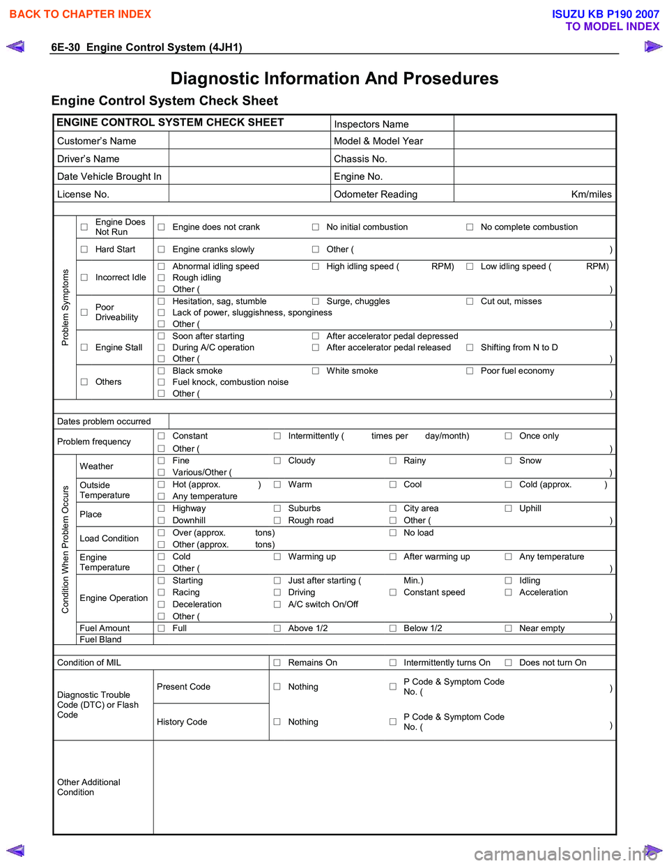
Diagnostic Information And Prosedures
Engine Control System Check Sheet
ENGINE CONTROL SYSTEM CHECK SHEET Inspectors Name
Customer’s Name Model & Model Year
Driver’s Name Chassis No.
Date Vehicle Brought In Engine No.
License No. Odometer Reading Km/miles
□ Engine Does
Not Run □
Engine does not crank
□No initial combustion
□ No complete combustion
□
Hard Start
□ Engine cranks slowly
□Other ( )
□
Abnormal idling speed
□High idling speed ( RPM)
□ Low idling speed ( RPM)
□
Rough idling □
Incorrect Idle
□ Other ( )
□
Hesitation, sag, stumble
□Surge, chuggles
□ Cut out, misses
□
Lack of power, sluggishness, sponginess □
Poor
Driveability □ Other ( )
□ Soon after starting
□After accelerator pedal depressed
Engine Stall
□ During A/C operation
□After accelerator pedal released
□ Shifting from N to D □
□ Other ( )
□
Black smoke
□White smoke
□ Poor fuel economy
□
Fuel knock, combustion noise
Problem Symptoms
□
Others
□ Other ( )
Dates problem occurred
□
Constant
□Intermittently ( times per day/month)
□ Once only Problem frequency
□ Other (
)
□ Fine
□Cloudy
□Rainy
□ Snow Weather
□ Various/Other (
)
□ Hot (approx. )
□Warm
□Cool
□ Cold (approx. )Outside
Temperature □ Any temperature
□
Highway
□Suburbs
□City area
□ Uphill Place
□ Downhill
□Rough road
□Other (
)
□ Over (approx. tons)
□No load
Load Condition
□ Other (approx. tons)
□ Cold
□Warming up
□After warming up
□ Any temperature Engine
Temperature □ Other ( )
□
Starting
□Just after starting ( Min.)
□ Idling
□
Racing
□Driving
□Constant speed
□ Acceleration
□
Deceleration
□A/C switch On/Off Engine Operation
□ Other ( )
Fuel Amount
□ Full
□Above 1/2
□Below 1/2
□ Near empty
Condition When Problem Occurs
Fuel
Bland
Condition of MIL
□Remains On
□Intermittently turns On
□ Does not turn On
Present Code
□Nothing
□P Code & Symptom Code
No. ( )Diagnostic Trouble
Code (DTC) or Flash
Code History Code □Nothing
□P Code & Symptom Code
No. ( )
Other Additional
Condition
BACK TO CHAPTER INDEX
TO MODEL INDEX
ISUZU KB P190 2007
Page 1065 of 6020
Engine Control System (4JH1) 6E-31
Diagnostic Starting Point - Engine Controls
Begin the system diagnosis with Diagnostic System
Check - Engine Controls. The Diagnostic System Check
- Engine Controls will provide the following information:
• The identification of the control modules which
command the system.
• The ability of the control modules to communicate
through the serial data circuit.
• The identification of any stored diagnostic trouble
codes (DTCs) and the their statuses.
The use of the Diagnostic System Check - Engine
Controls will identify the correct procedure fo
r
diagnosing the system and where the procedure is
located.
Important:
Engine Control System Check Sheet must be used to
verify the complaint vehicle, you need to know the
correct (normal) operating behavior of the system and
verify that the customer complaint is a valid failure o
f
the system.
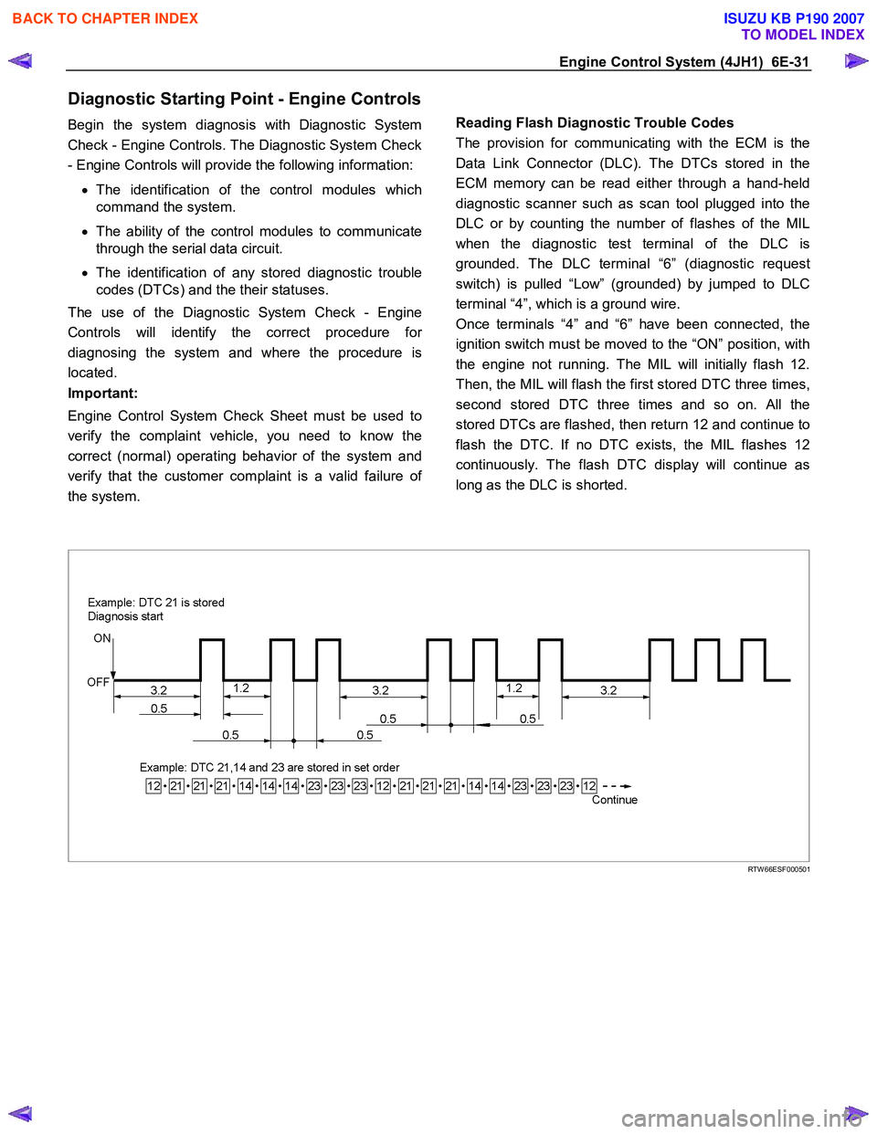
Reading Flash Diagnostic Trouble Codes
The provision for communicating with the ECM is the
Data Link Connector (DLC). The DTCs stored in the
ECM memory can be read either through a hand-held
diagnostic scanner such as scan tool plugged into the
DLC or by counting the number of flashes of the MIL
when the diagnostic test terminal of the DLC is
grounded. The DLC terminal “6” (diagnostic request
switch) is pulled “Low” (grounded) by jumped to DLC
terminal “4”, which is a ground wire.
Once terminals “4” and “6” have been connected, the
ignition switch must be moved to the “ON” position, with
the engine not running. The MIL will initially flash 12.
Then, the MIL will flash the first stored DTC three times,
second stored DTC three times and so on. All the
stored DTCs are flashed, then return 12 and continue to
flash the DTC. If no DTC exists, the MIL flashes 12
continuously. The flash DTC display will continue as
long as the DLC is shorted.
RTW 66ESF000501
BACK TO CHAPTER INDEX
TO MODEL INDEX
ISUZU KB P190 2007