2007 ISUZU KB P190 cruise control
[x] Cancel search: cruise controlPage 1932 of 6020
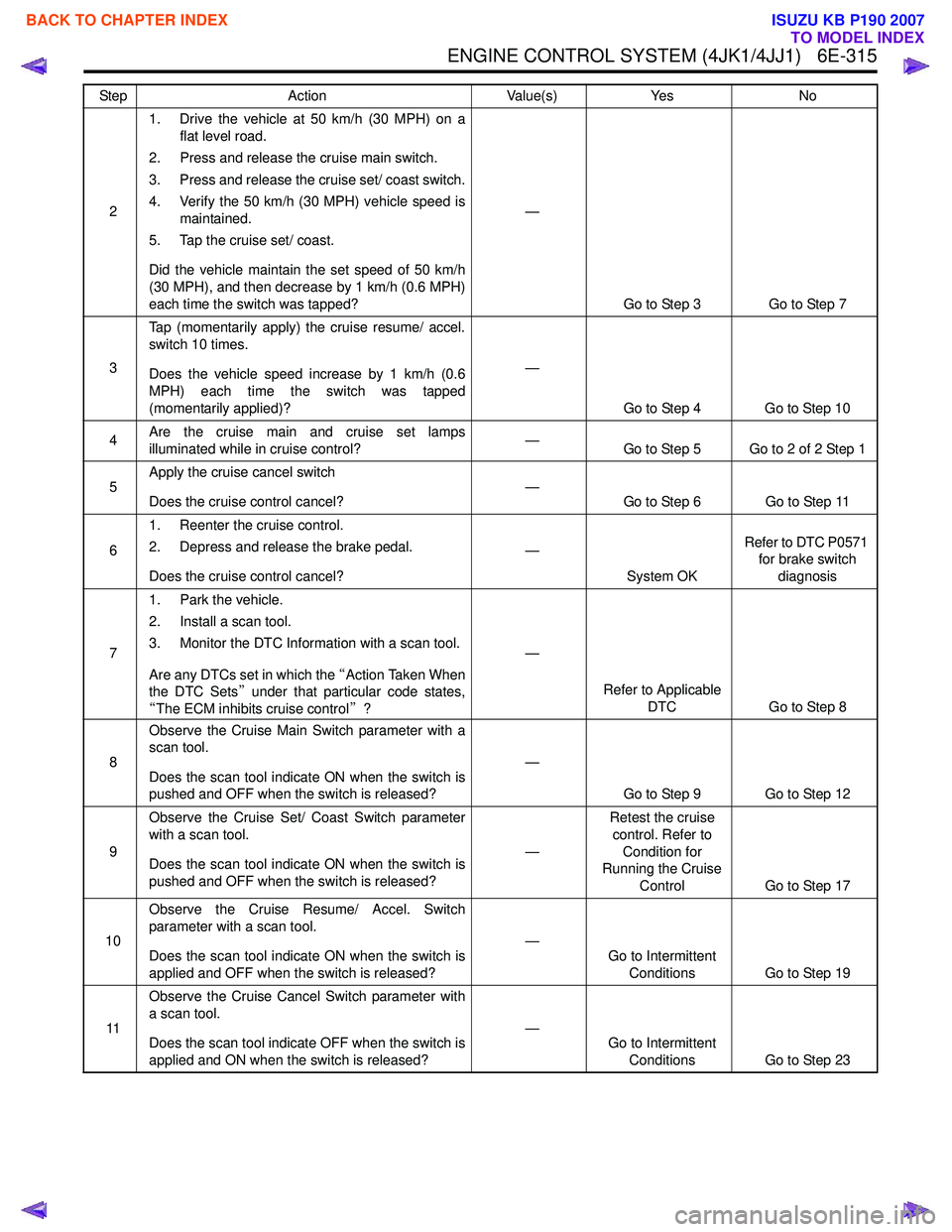
ENGINE CONTROL SYSTEM (4JK1/4JJ1) 6E-315
21. Drive the vehicle at 50 km/h (30 MPH) on a
flat level road.
2. Press and release the cruise main switch.
3. Press and release the cruise set/ coast switch.
4. Verify the 50 km/h (30 MPH) vehicle speed is maintained.
5. Tap the cruise set/ coast.
Did the vehicle maintain the set speed of 50 km/h
(30 MPH), and then decrease by 1 km/h (0.6 MPH)
each time the switch was tapped? —
Go to Step 3 Go to Step 7
3 Tap (momentarily apply) the cruise resume/ accel.
switch 10 times.
Does the vehicle speed increase by 1 km/h (0.6
MPH) each time the switch was tapped
(momentarily applied)? —
Go to Step 4 Go to Step 10
4 Are the cruise main and cruise set lamps
illuminated while in cruise control? —
Go to Step 5 Go to 2 of 2 Step 1
5 Apply the cruise cancel switch
Does the cruise control cancel? —
Go to Step 6 Go to Step 11
6 1. Reenter the cruise control.
2. Depress and release the brake pedal.
Does the cruise control cancel? —
System OK Refer to DTC P0571
for brake switch
diagnosis
7 1. Park the vehicle.
2. Install a scan tool.
3. Monitor the DTC Information with a scan tool.
Are any DTCs set in which the “Action Taken When
the DTC Sets ” under that particular code states,
“ The ECM inhibits cruise control ”? —
Refer to Applicable DTC Go to Step 8
8 Observe the Cruise Main Switch parameter with a
scan tool.
Does the scan tool indicate ON when the switch is
pushed and OFF when the switch is released? —
Go to Step 9 Go to Step 12
9 Observe the Cruise Set/ Coast Switch parameter
with a scan tool.
Does the scan tool indicate ON when the switch is
pushed and OFF when the switch is released? —Retest the cruise
control. Refer to Condition for
Running the Cruise
Control Go to Step 17
10 Observe the Cruise Resume/ Accel. Switch
parameter with a scan tool.
Does the scan tool indicate ON when the switch is
applied and OFF when the switch is released? —
Go to Intermittent
Conditions Go to Step 19
11 Observe the Cruise Cancel Switch parameter with
a scan tool.
Does the scan tool indicate OFF when the switch is
applied and ON when the switch is released? —
Go to Intermittent
Conditions Go to Step 23
Step
Action Value(s)Yes No
BACK TO CHAPTER INDEX
TO MODEL INDEX
ISUZU KB P190 2007
Page 1933 of 6020
6E-316 ENGINE CONTROL SYSTEM (4JK1/4JJ1)
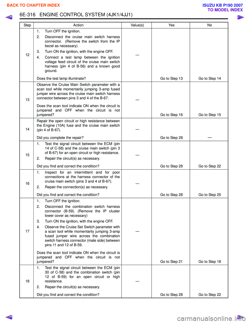
121. Turn OFF the ignition.
2. Disconnect the cruise main switch harness connector. (Remove the switch from the IP
bezel as necessary)
3. Turn ON the ignition, with the engine OFF.
4. Connect a test lamp between the ignition voltage feed circuit of the cruise main switch
harness (pin 4 of B-56) and a known good
ground.
Does the test lamp illuminate? —
Go to Step 13 Go to Step 14
13 Observe the Cruise Main Switch parameter with a
scan tool while momentarily jumping 3-amp fused
jumper wire across the cruise main switch harness
connector between pins 3 and 4 of the B-67.
Does the scan tool indicate ON when the circuit is
jumpered and OFF when the circuit is not
jumpered? —
Go to Step 16 Go to Step 15
14 Repair the open circuit or high resistance between
the Engine (10A) fuse and the cruise main switch
(pin 4 of B-67).
Did you complete the repair? —
Go to Step 28
—
151. Test the signal circuit between the ECM (pin
14 of C-58) and the cruise main switch (pin 3
of B-67) for an open circuit or high resistance.
2. Repair the circuit(s) as necessary.
Did you find and correct the condition? —
Go to Step 28 Go to Step 22
16 1. Inspect for an intermittent and for poor
connections at the harness connector of the
cruise main switch (pins 3 and 4 of B-67).
2. Repair the connection(s) as necessary.
Did you find and correct the condition? —
Go to Step 28 Go to Step 25
17 1. Turn OFF the ignition.
2. Disconnect the combination switch harness connector (B-59). (Remove the IP cluster
lower cover as necessary)
3. Turn ON the ignition, with the engine OFF.
4. Observe the Cruise Set Switch parameter with a scan tool while momentarily jumping 3-amp
fused jumper wire across the combination
switch harness connector (male side) between
pins 11 and 12 of B-59.
Does the scan tool indicate ON when the circuit is
jumpered and OFF when the circuit is not
jumpered? —
Go to Step 21 Go to Step 18
18 1. Test the signal circuit between the ECM (pin
30 of C-58) and the combination switch (pin
12 of B-59) for an open circuit or high
resistance.
2. Repair the circuit(s) as necessary.
Did you find and correct the condition? —
Go to Step 28 Go to Step 22
Step
Action Value(s)Yes No
BACK TO CHAPTER INDEX
TO MODEL INDEX
ISUZU KB P190 2007
Page 1934 of 6020
ENGINE CONTROL SYSTEM (4JK1/4JJ1) 6E-317
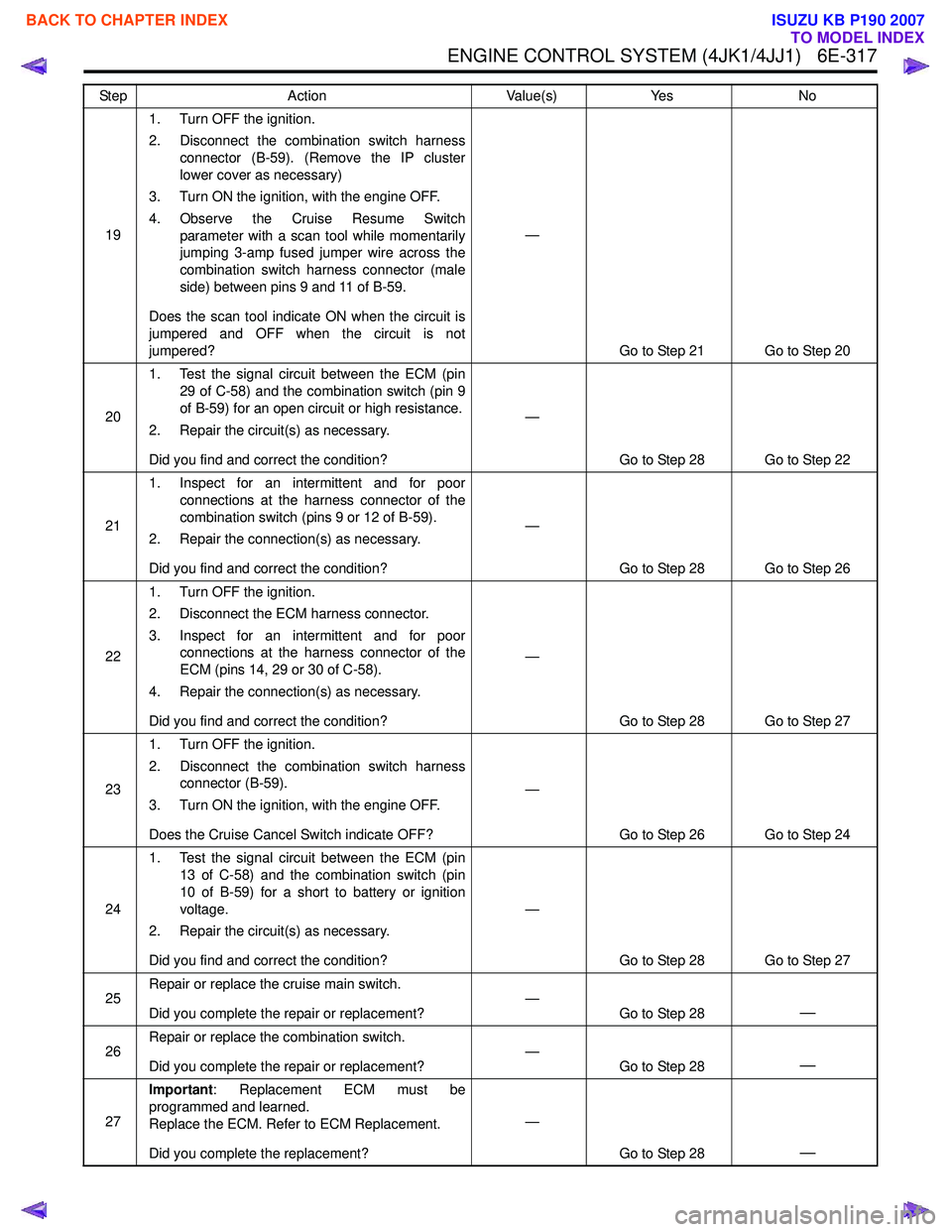
191. Turn OFF the ignition.
2. Disconnect the combination switch harness connector (B-59). (Remove the IP cluster
lower cover as necessary)
3. Turn ON the ignition, with the engine OFF.
4. Observe the Cruise Resume Switch parameter with a scan tool while momentarily
jumping 3-amp fused jumper wire across the
combination switch harness connector (male
side) between pins 9 and 11 of B-59.
Does the scan tool indicate ON when the circuit is
jumpered and OFF when the circuit is not
jumpered? —
Go to Step 21 Go to Step 20
20 1. Test the signal circuit between the ECM (pin
29 of C-58) and the combination switch (pin 9
of B-59) for an open circuit or high resistance.
2. Repair the circuit(s) as necessary.
Did you find and correct the condition? —
Go to Step 28 Go to Step 22
21 1. Inspect for an intermittent and for poor
connections at the harness connector of the
combination switch (pins 9 or 12 of B-59).
2. Repair the connection(s) as necessary.
Did you find and correct the condition? —
Go to Step 28 Go to Step 26
22 1. Turn OFF the ignition.
2. Disconnect the ECM harness connector.
3. Inspect for an intermittent and for poor connections at the harness connector of the
ECM (pins 14, 29 or 30 of C-58).
4. Repair the connection(s) as necessary.
Did you find and correct the condition? —
Go to Step 28 Go to Step 27
23 1. Turn OFF the ignition.
2. Disconnect the combination switch harness connector (B-59).
3. Turn ON the ignition, with the engine OFF.
Does the Cruise Cancel Switch indicate OFF? —
Go to Step 26 Go to Step 24
24 1. Test the signal circuit between the ECM (pin
13 of C-58) and the combination switch (pin
10 of B-59) for a short to battery or ignition
voltage.
2. Repair the circuit(s) as necessary.
Did you find and correct the condition? —
Go to Step 28 Go to Step 27
25 Repair or replace the cruise main switch.
Did you complete the repair or replacement? —
Go to Step 28
—
26Repair or replace the combination switch.
Did you complete the repair or replacement? —
Go to Step 28—
27Important
: Replacement ECM must be
programmed and learned.
Replace the ECM. Refer to ECM Replacement.
Did you complete the replacement? —
Go to Step 28
—
Step Action Value(s)Yes No
BACK TO CHAPTER INDEX
TO MODEL INDEX
ISUZU KB P190 2007
Page 1935 of 6020
6E-318 ENGINE CONTROL SYSTEM (4JK1/4JJ1)
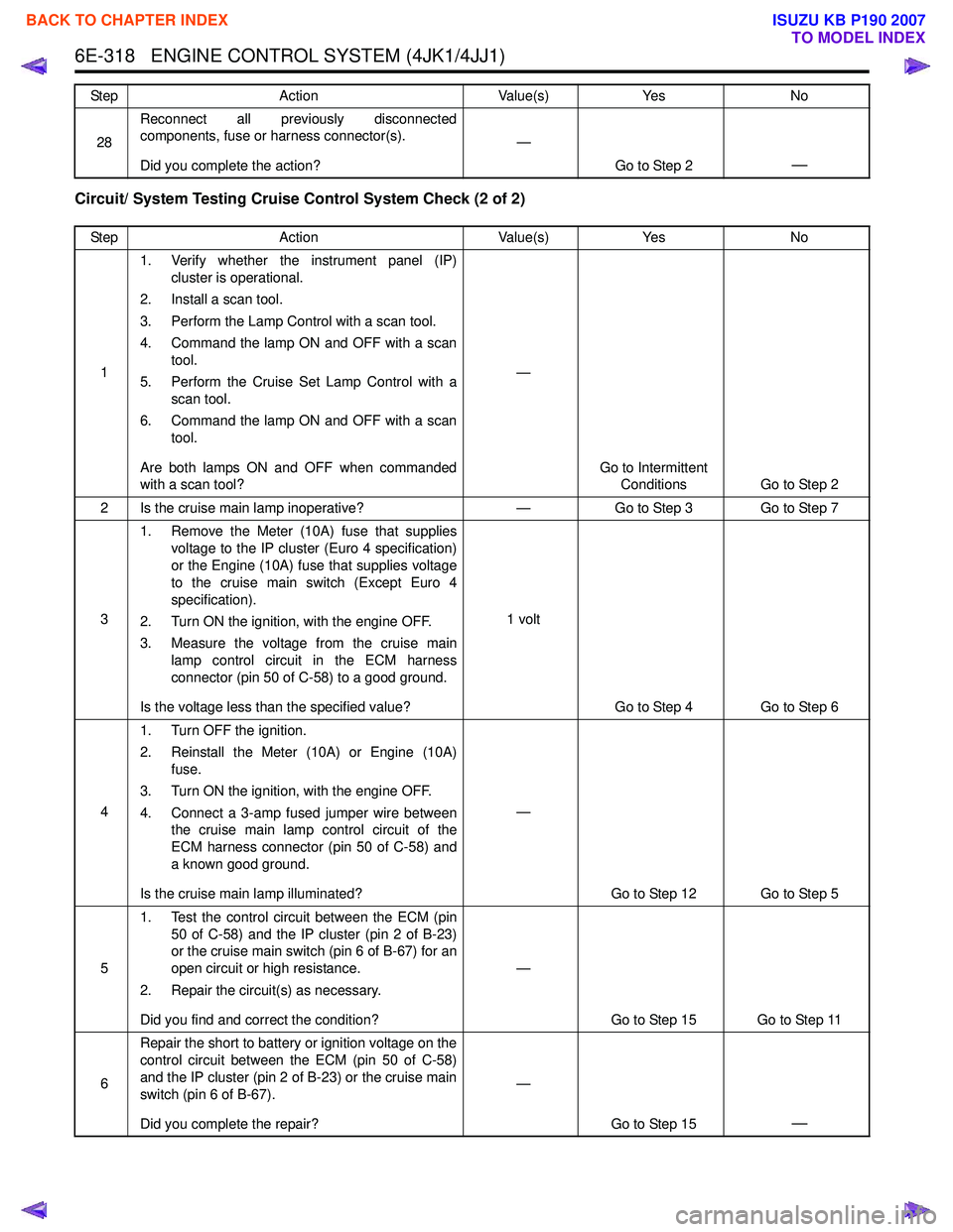
Circuit/ System Testing Cruise Control System Check (2 of 2)
28Reconnect all previously disconnected
components, fuse or harness connector(s).
Did you complete the action? —
Go to Step 2
—
Step Action Value(s)Yes No
1 1. Verify whether the instrument panel (IP)
cluster is operational.
2. Install a scan tool.
3. Perform the Lamp Control with a scan tool.
4. Command the lamp ON and OFF with a scan tool.
5. Perform the Cruise Set Lamp Control with a scan tool.
6. Command the lamp ON and OFF with a scan tool.
Are both lamps ON and OFF when commanded
with a scan tool? —
Go to Intermittent Conditions Go to Step 2
2 Is the cruise main lamp inoperative? —Go to Step 3 Go to Step 7
3 1. Remove the Meter (10A) fuse that supplies
voltage to the IP cluster (Euro 4 specification)
or the Engine (10A) fuse that supplies voltage
to the cruise main switch (Except Euro 4
specification).
2. Turn ON the ignition, with the engine OFF.
3. Measure the voltage from the cruise main lamp control circuit in the ECM harness
connector (pin 50 of C-58) to a good ground.
Is the voltage less than the specified value? 1 volt
Go to Step 4 Go to Step 6
4 1. Turn OFF the ignition.
2. Reinstall the Meter (10A) or Engine (10A) fuse.
3. Turn ON the ignition, with the engine OFF.
4. Connect a 3-amp fused jumper wire between the cruise main lamp control circuit of the
ECM harness connector (pin 50 of C-58) and
a known good ground.
Is the cruise main lamp illuminated? —
Go to Step 12 Go to Step 5
5 1. Test the control circuit between the ECM (pin
50 of C-58) and the IP cluster (pin 2 of B-23)
or the cruise main switch (pin 6 of B-67) for an
open circuit or high resistance.
2. Repair the circuit(s) as necessary.
Did you find and correct the condition? —
Go to Step 15 Go to Step 11
6 Repair the short to battery or ignition voltage on the
control circuit between the ECM (pin 50 of C-58)
and the IP cluster (pin 2 of B-23) or the cruise main
switch (pin 6 of B-67).
Did you complete the repair? —
Go to Step 15
—
Step Action Value(s)Yes No
BACK TO CHAPTER INDEX
TO MODEL INDEX
ISUZU KB P190 2007
Page 1936 of 6020
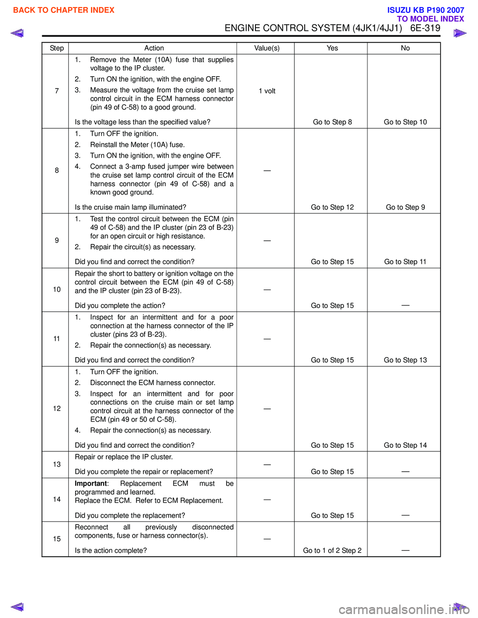
ENGINE CONTROL SYSTEM (4JK1/4JJ1) 6E-319
71. Remove the Meter (10A) fuse that supplies
voltage to the IP cluster.
2. Turn ON the ignition, with the engine OFF.
3. Measure the voltage from the cruise set lamp control circuit in the ECM harness connector
(pin 49 of C-58) to a good ground.
Is the voltage less than the specified value? 1 volt
Go to Step 8 Go to Step 10
8 1. Turn OFF the ignition.
2. Reinstall the Meter (10A) fuse.
3. Turn ON the ignition, with the engine OFF.
4. Connect a 3-amp fused jumper wire between the cruise set lamp control circuit of the ECM
harness connector (pin 49 of C-58) and a
known good ground.
Is the cruise main lamp illuminated? —
Go to Step 12 Go to Step 9
9 1. Test the control circuit between the ECM (pin
49 of C-58) and the IP cluster (pin 23 of B-23)
for an open circuit or high resistance.
2. Repair the circuit(s) as necessary.
Did you find and correct the condition? —
Go to Step 15 Go to Step 11
10 Repair the short to battery or ignition voltage on the
control circuit between the ECM (pin 49 of C-58)
and the IP cluster (pin 23 of B-23).
Did you complete the action? —
Go to Step 15
—
111. Inspect for an intermittent and for a poor
connection at the harness connector of the IP
cluster (pins 23 of B-23).
2. Repair the connection(s) as necessary.
Did you find and correct the condition? —
Go to Step 15 Go to Step 13
12 1. Turn OFF the ignition.
2. Disconnect the ECM harness connector.
3. Inspect for an intermittent and for poor connections on the cruise main or set lamp
control circuit at the harness connector of the
ECM (pin 49 or 50 of C-58).
4. Repair the connection(s) as necessary.
Did you find and correct the condition? —
Go to Step 15 Go to Step 14
13 Repair or replace the IP cluster.
Did you complete the repair or replacement? —
Go to Step 15
—
14Important
: Replacement ECM must be
programmed and learned.
Replace the ECM. Refer to ECM Replacement.
Did you complete the replacement? —
Go to Step 15
—
15Reconnect all previously disconnected
components, fuse or harness connector(s).
Is the action complete? —
Go to 1 of 2 Step 2
—
Step Action Value(s)Yes No
BACK TO CHAPTER INDEX
TO MODEL INDEX
ISUZU KB P190 2007
Page 1951 of 6020
6E-334 ENGINE CONTROL SYSTEM (4JK1/4JJ1)
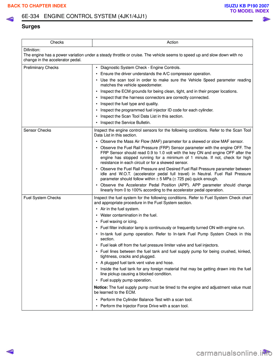
Surges
ChecksAction
Difinition:
The engine has a power variation under a steady throttle or cruise. The vehicle seems to speed up and slow down with no
change in the accelerator pedal.
Preliminary Checks • Diagnostic System Check - Engine Controls.
• Ensure the driver understands the A/C compressor operation.
• Use the scan tool in order to make sure the Vehicle Speed parameter reading matches the vehicle speedometer.
• Inspect the ECM grounds for being clean, tight, and in their proper locations.
• Inspect that the harness connectors are correctly connected.
• Inspect the fuel type and quality.
• Inspect the programmed fuel injector ID code for each cylinder.
• Inspect the Scan Tool Data List in this section.
• Inspect the Service Bulletin.
Sensor Checks Inspect the engine control sensors for the following conditions. Refer to the Scan Tool
Data List in this section.
• Observe the Mass Air Flow (MAF) parameter for a skewed or slow MAF sensor.
• Observe the Fuel Rail Pressure (FRP) Sensor parameter with the engine OFF. The FRP Sensor should read 0.9 to 1.0 volt with the key ON and engine OFF after the
engine has stopped running for a minimum of 1 minute. If not, check for high
resistance in each circuit or for a skewed sensor.
• Observe the Fuel Rail Pressure and Desired Fuel Rail Pressure parameter between idle and W.O.T. (accelerator pedal full travel) in Neutral. Fuel Rail Pressure
parameter should follow within ± 5 MPa ( ± 725 psi) quick enough.
• Observe the Accelerator Pedal Position (APP). APP parameter should change linearly from 0 to 100% according to the accelerator pedal operation.
Fuel System Checks Inspect the fuel system for the following conditions. Refer to Fuel System Check chart
and appropriate procedure in the Fuel System section.
• Air in the fuel system.
• Water contamination in the fuel.
• Fuel waxing or icing.
• Fuel filter indicator lamp is continuously or frequently turned ON with engine run.
• In-tank fuel pump operation. Refer to In-tank Fuel Pump System Check in this section.
• Fuel leak off from the fuel pressure limiter valve and fuel injectors.
• Fuel lines between the fuel tank and fuel supply pump for being crushed, kinked, tightness, cracks and plugged.
• A plugged fuel tank vent valve and hose.
• Inside the fuel tank for any foreign material that may be getting drawn into the fuel line pickup causing a blocked condition.
• Fuel supply pump operation.
Notice: The fuel supply pump must be timed to the engine and adjustment value must
be learned to the ECM.
• Perform the Cylinder Balance Test with a scan tool.
• Perform the Injector Force Drive with a scan tool.
BACK TO CHAPTER INDEX
TO MODEL INDEX
ISUZU KB P190 2007
Page 1971 of 6020
6E-354 ENGINE CONTROL SYSTEM (4JK1/4JJ1)
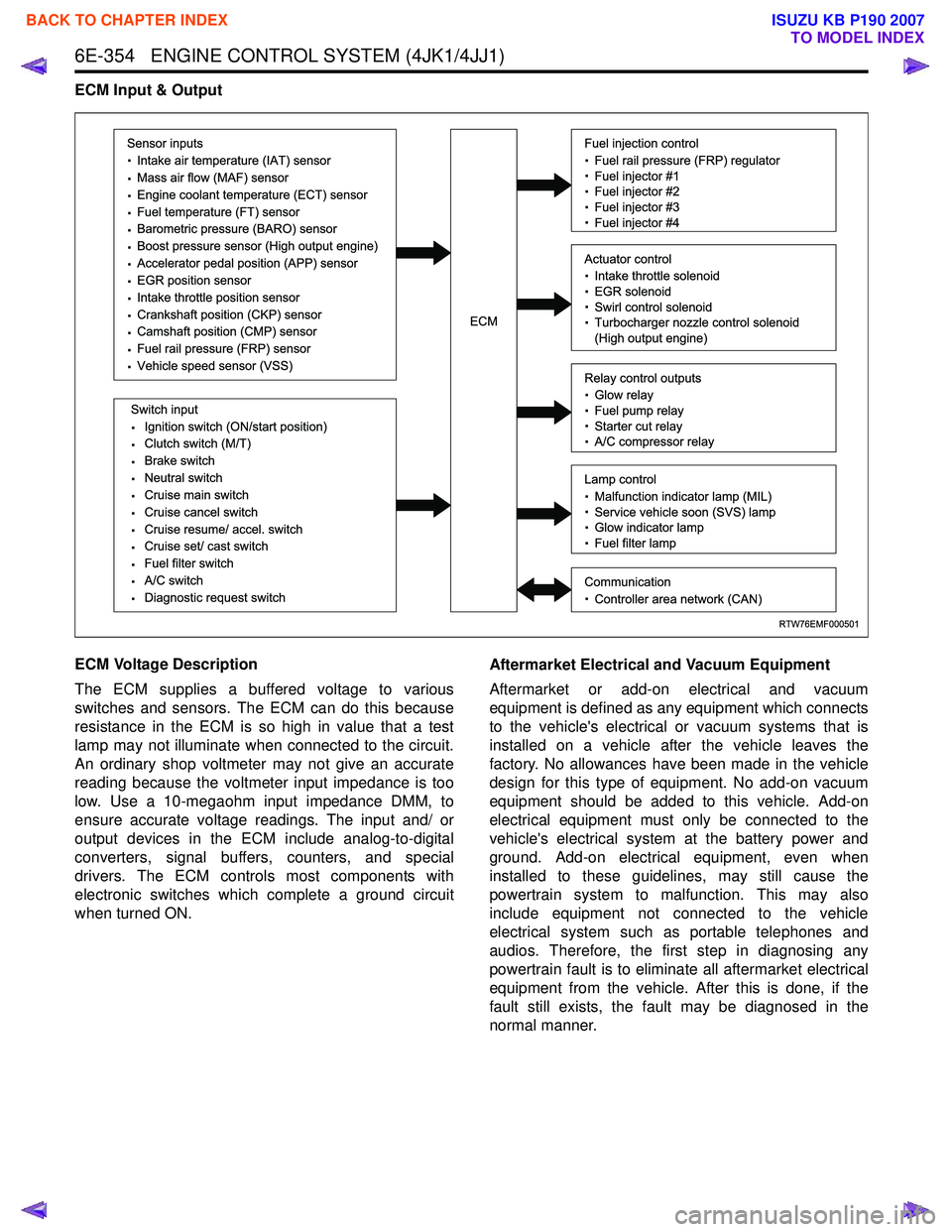
ECM Input & Output
ECM Voltage Description
The ECM supplies a buffered voltage to various
switches and sensors. The ECM can do this because
resistance in the ECM is so high in value that a test
lamp may not illuminate when connected to the circuit.
An ordinary shop voltmeter may not give an accurate
reading because the voltmeter input impedance is too
low. Use a 10-megaohm input impedance DMM, to
ensure accurate voltage readings. The input and/ or
output devices in the ECM include analog-to-digital
converters, signal buffers, counters, and special
drivers. The ECM controls most components with
electronic switches which complete a ground circuit
when turned ON. Aftermarket Electrical and Vacuum Equipment
Aftermarket or add-on electrical and vacuum
equipment is defined as any equipment which connects
to the vehicle's electrical or vacuum systems that is
installed on a vehicle after the vehicle leaves the
factory. No allowances have been made in the vehicle
design for this type of equipment. No add-on vacuum
equipment should be added to this vehicle. Add-on
electrical equipment must only be connected to the
vehicle's electrical system at the battery power and
ground. Add-on electrical equipment, even when
installed to these guidelines, may still cause the
powertrain system to malfunction. This may also
include equipment not connected to the vehicle
electrical system such as portable telephones and
audios. Therefore, the first step in diagnosing any
powertrain fault is to eliminate all aftermarket electrical
equipment from the vehicle. After this is done, if the
fault still exists, the fault may be diagnosed in the
normal manner.
RTW76EMF000501
Sensor inputs
· Intake air temperature (IAT) sensor
· Mass air flow (MAF) sensor
· Engine coolant temperature (ECT) sensor
· Fuel temperature (FT) sensor
· Barometric pressure (BARO) sensor
· Boost pressure sensor (High output engine)
· Accelerator pedal position (APP) sensor
· EGR position sensor
· Intake throttle position sensor
· Crankshaft position (CKP) sensor
· Camshaft position (CMP) sensor
· Fuel rail pressure (FRP) sensor
· Vehicle speed sensor (VSS)
Switch input
· Ignition switch (ON/start position)
· Clutch switch (M/T)
· Brake switch
· Neutral switch
· Cruise main switch
· Cruise cancel switch
· Cruise resume/ accel. switch
· Cruise set/ cast switch
· Fuel filter switch
· A/C switch
· Diagnostic request switch
Fuel injection control
· Fuel rail pressure (FRP) regulator
· Fuel injector #1
· Fuel injector #2
· Fuel injector #3
· Fuel injector #4
Relay control outputs
· Glow relay
· Fuel pump relay
· Starter cut relay
· A/C compressor relay
Lamp control
· Malfunction indicator lamp (MIL)
· Service vehicle soon (SVS) lamp
· Glow indicator lamp
· Fuel filter lamp
Communication
· Controller area network (CAN)
Actuator control
· Intake throttle solenoid
· EGR solenoid
· Swirl control solenoid
· Turbocharger nozzle control solenoid
(High output engine)ECM
BACK TO CHAPTER INDEX
TO MODEL INDEX
ISUZU KB P190 2007
Page 3243 of 6020
Engine Management – V6 – General Information Page 6C1-1–1
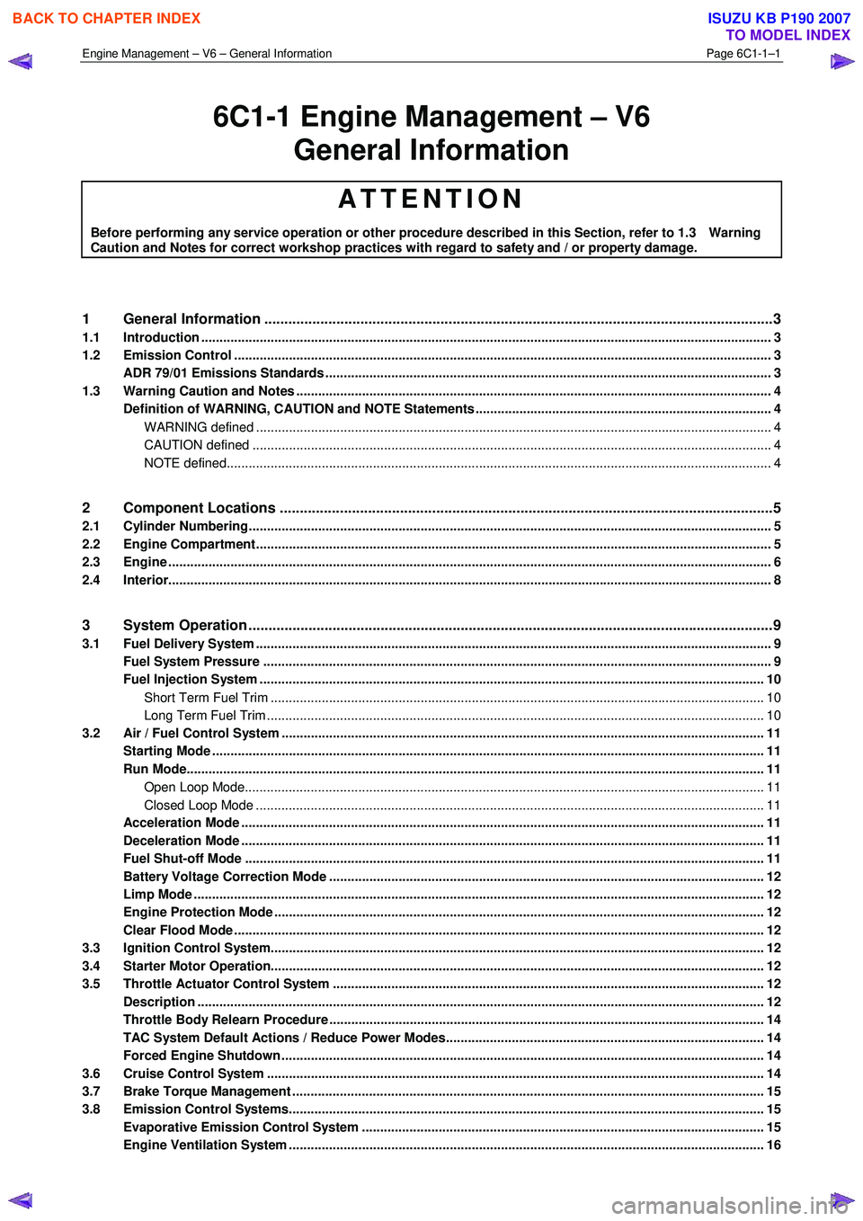
6C1-1 Engine Management – V6
General Information
ATTENTION
Before performing any service operation or other procedure described in this Section, refer to 1.3 Warning
Caution and Notes for correct workshop practices with regard to safety and / or property damage.
1 General Information ............................................................................................................ ...................3
1.1 Introduction ............................................................................................................................................................ 3
1.2 Emission Control ................................................................................................................................................... 3
ADR 79/01 Emissions Standards .......................................................................................................................... 3
1.3 Warning Caution and Notes .................................................................................................................................. 4
Definition of WARNING, CAUTION and NOTE Statements ............................................................................. .... 4
WARNING defined ............................................................................................................................................. 4
CAUTION defined .............................................................................................................................................. 4
NOTE defined..................................................................................................................................................... 4
2 Component Locations ............................................................................................................ ...............5
2.1 Cylinder Numbering............................................................................................................................................... 5
2.2 Engine Compartment............................................................................................................................................. 5
2.3 Engine ..................................................................................................................................................................... 6
2.4 Interior..................................................................................................................................................................... 8
3 System Operation ...................................................................................................................................9
3.1 Fuel Delivery System ............................................................................................................................................. 9
Fuel System Pressure ........................................................................................................... ................................ 9
Fuel Injection System .......................................................................................................................................... 10
Short Term Fuel Trim ....................................................................................................................................... 10
Long Term Fuel Trim ........................................................................................................................................ 10
3.2 Air / Fuel Control System ...................................................................................................... .............................. 11
Starting Mode ....................................................................................................................................................... 11
Run Mode.............................................................................................................................................................. 11
Open Loop Mode................................................................................................................. ............................. 11
Closed Loop Mode ............................................................................................................... ............................ 11
Acceleration Mode .............................................................................................................. ................................. 11
Deceleration Mode ............................................................................................................................................... 11
Fuel Shut-off Mode .............................................................................................................................................. 11
Battery Voltage Correction Mode ................................................................................................ ....................... 12
Limp Mode ............................................................................................................................................................ 12
Engine Protection Mode ......................................................................................................... ............................. 12
Clear Flood Mode ................................................................................................................................................. 12
3.3 Ignition Control System........................................................................................................ ............................... 12
3.4 Starter Motor Operation....................................................................................................................................... 12
3.5 Throttle Actuator Control System ............................................................................................... ....................... 12
Description ........................................................................................................................................................... 12
Throttle Body Relearn Procedure ....................................................................................................................... 14
TAC System Default Actions / Reduce Power Modes................................................................................ ....... 14
Forced Engine Shutdown .................................................................................................................................... 14
3.6 Cruise Control System ........................................................................................................................................ 14
3.7 Brake Torque Management ........................................................................................................ ......................... 15
3.8 Emission Control Systems.................................................................................................................................. 15
Evaporative Emission Control System ............................................................................................ .................. 15
Engine Ventilation System .................................................................................................................................. 16
BACK TO CHAPTER INDEX
TO MODEL INDEX
ISUZU KB P190 2007