2007 ISUZU KB P190 oil temperature
[x] Cancel search: oil temperaturePage 2792 of 6020
Engine Mechanical – V6 Page 6A1–15
Page 6A1–15
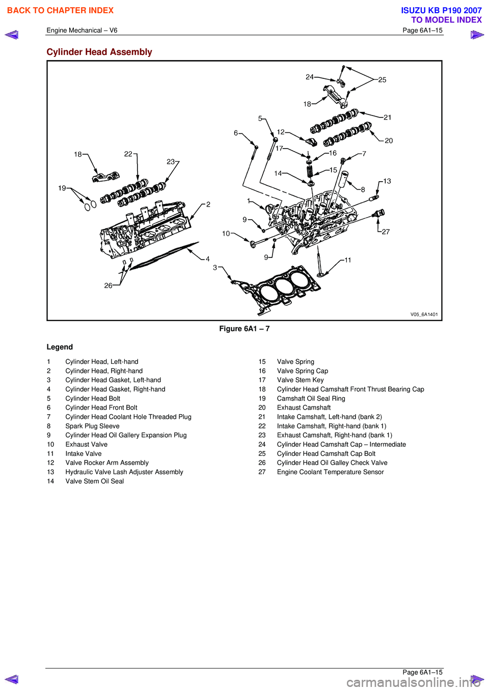
Cylinder Head Assembly
Figure 6A1 – 7
Legend
1 Cylinder Head, Left-hand
2 Cylinder Head, Right-hand
3 Cylinder Head Gasket, Left-hand
4 Cylinder Head Gasket, Right-hand
5 Cylinder Head Bolt
6 Cylinder Head Front Bolt
7 Cylinder Head Coolant Hole Threaded Plug
8 Spark Plug Sleeve
9 Cylinder Head Oil Gallery Expansion Plug
10 Exhaust Valve
11 Intake Valve
12 Valve Rocker Arm Assembly
13 Hydraulic Valve Lash Adjuster Assembly
14 Valve Stem Oil Seal 15 Valve Spring
16 Valve Spring Cap
17 Valve Stem Key
18 Cylinder Head Camshaft Front Thrust Bearing Cap
19 Camshaft Oil Seal Ring
20 Exhaust Camshaft
21 Intake Camshaft, Left-hand (bank 2)
22 Intake Camshaft, Right-hand (bank 1)
23 Exhaust Camshaft, Right-hand (bank 1)
24 Cylinder Head Camshaft Cap – Intermediate
25 Cylinder Head Camshaft Cap Bolt
26 Cylinder Head Oil Galley Check Valve
27 Engine Coolant Temperature Sensor
BACK TO CHAPTER INDEX
TO MODEL INDEX
ISUZU KB P190 2007
Page 2802 of 6020
Engine Mechanical – V6 Page 6A1–25
Page 6A1–25
1.5 Engine Lubrication System
Lubrication Description
A structural diecast aluminium oil pan is fitted that incorporates an oil suction pipe, an oil deflector and an oil level
sensor. The oil suction pipe is bolted in to the oil pan and seals to the bottom of the cylinder block with a gasket. The oil
deflector is bolted to the upper portion of the oil pan and ensures oil supply is maintained under all conditions. The oil
level sensor is mounted thr ough the bottom of the oil pan.
A crankshaft driven gerotor oil pump is mounted to the front of the cylinder block. The pump, which incorporates an
internal pressure-relief valve, draws oil from the oil sucti on tube through the lower passage in the cylinder block. Oil is
then directed through an upper passage to the left-hand side of the cylinder block where the oil filter adapter is mounted.
The oil filter adapter incorporat es a top-access, cartridge style oil filter. The filter is accessed through a screw-on cap tha t
incorporates an oil bypass valve. The o il filter adapter housing incorporates a drain back control valve and a threaded oil
pressure sender. Oil flows through a lower passage within the oil filter adapter and through the o il filter cartridge. Filtered
oil travels back through the upper passage of the adapter and into the engine block.
Oil is then directed up and across the front of the cylinder block, through several drilled passages. These front passages
feed oil to each cylinder head, the passage for the main bearings and piston oil jets, the right-hand and left-hand
secondary idler sprockets and to t he primary timing chain tensioner.
Each cylinder head passage directs oil into oiling circuits for the stationary hydraulic la sh adjusters (SHLAs) and the
camshaft bearing journals. An additional passage in the cy linder head also directs oil to the secondary timing chain
tensioner.
The oil passage that supplies oil to the main bearings also s upplies oil to pressure actuated piston cooling oil jets. Each
oil jet is mounted between opposing cylinder bores and directs oil to the two bores to provide extra cooling and control
piston temperatures.
From the front passages, oil is directed to the front of the block where t he right-hand and left-hand intermediate drive
shaft sprockets and the primary timing chain tensioner are mounted. Each camshaft timing chain tensioner relies on a
gasket to maintain an oil rese rve after the engine is turned off. All camshaft timing chain tensioners incorporate a small
oil jet to supply an oil spray onto the camshaft timing chain components.
Oil returns to the oil pan, either through the camshaft timing chain area or through the drain back passages on the
outboard walls of the cylinder heads and cylinder block.
BACK TO CHAPTER INDEX
TO MODEL INDEX
ISUZU KB P190 2007
Page 2804 of 6020
Engine Mechanical – V6 Page 6A1–27
Page 6A1–27
Use of Room Temperature Vulcanising and Anaerobic Sealer
CAUTION
A number of sealant types are commonly
used in engines. Examples are; room
temperature vulcanising (RTV) sealer,
anaerobic gasket eliminator sealer, and
anaerobic thread sealant and pipe joint
compound. The correct type of sealant and
amount must be used in the specified location
to prevent oil leaks. Do not interchange the
different types of sealers.
Room Temperature Vulcanising Sealer
• Room temperature vulcanising (RTV) s ealant hardens when exposed to air. This type of sealer is used where two
non-rigid parts (such as the intake manifold and the engine block) are assembled together.
• Do not use RTV sealant in areas where extreme temper atures are experienced. These areas include the exhaust
manifold, head gasket, or other surfaces w here a gasket eliminator is specified.
• Follow all safety recommendations and di rections that are on the container.
• To remove the sealant or the gasket mate rial, refer to Replacing Engine Gaskets.
• Apply RTV to a clean surface. Use a bead size as specified in the service procedure. Run the bead to the inside of
any bolt holes. Do not allow the sealer to enter any bli nd threaded holes, as it may prevent the bolt from clamping
correctly or cause damage when the bolt is tightened.
• Assemble components while RTV is still wet (within 3 minutes). Do not wait for RTV to skin over.
• Tighten the bolts to the correct torque specification. Do not over-tighten.
Anaerobic Sealer
• Anaerobic gasket eliminator or thread sealant, hardens in t he absence of air. This type sealer is used where two
rigid parts (such as castings) are assembled together, w here fasteners are subjected to vibration, or where the
holes are not blind. When two rigid parts are disassembled and no sealer or gasket is readily noticeable, the parts
were probably assembled using a gasket eliminator.
• Follow all safety recommendations and di rections that are on the container.
• To remove the sealant or the gasket mate rial, refer to Replacing Engine Gaskets.
• Apply a continuous bead of gasket eliminator to one flange or on the bolt/stud thread. All surfaces must be clean
and dry.
• Spread the sealer evenly to achieve a uniform coating on the sealing surface.
• Do not allow the sealer to enter any blind threaded holes as it may prevent the bolt from clamping correctly or
cause damage when tightened.
CAUTION
Anaerobic sealed joints that are partially
tightened and allowed to cure more than five
minutes may result in incorrect shimming and
sealing of the joint.
• Tighten the bolts to the correct torque specification. Do not over-tighten.
• After correctly tightening the fasteners, remove t he excess sealer from the outside of the joint.
BACK TO CHAPTER INDEX
TO MODEL INDEX
ISUZU KB P190 2007
Page 2805 of 6020
Engine Mechanical – V6 Page 6A1–28
Page 6A1–28
Pipe Joint Compound
• Pipe joint compound is a pliable sealer that does not comp letely harden. This type of sealer is used where two non-
rigid parts (such as pressed steel and ma chined surfaces) are assembled together.
• Do not use pipe joint compound in areas where extreme temperatures are expected. These areas include the
exhaust manifold, head gasket, or other surfaces where gasket eliminator is specified.
• Follow all safety recommendations and di rections that are on the container.
• To remove the sealant or the gasket mate rial, refer to Replacing Engine Gaskets.
• Apply the pipe joint compound to a clean surface. Use a bead size or quantity as specified in the procedure. Run
the bead to the inside of any bolt holes. Do not allow the s ealer to enter any blind threaded holes as it may prevent
the bolt from clamping correctly or caus e component damage when the bolt is tightened.
• Apply a continuous bead of pipe joint compound to one seali ng surface. Sealing surfaces to be resealed must be
clean and dry.
• Tighten the bolts to the correct torque specification. Do not over-tighten.
Separating Parts
CAUTION
Many internal engine components will
develop specific wear patterns on their
friction surfaces. When disassembling the
engine, internal components must be
separated, marked and organised in a way to
ensure reinstallation in their original location
and position.
Separate, mark, or organise the following components:
• Piston and the piston pin.
• Piston to the specific cylinder bore.
• Piston rings to the specific piston.
• Connecting rod to the crankshaft journal.
• Connecting rod to the bearing cap.
• Crankshaft main and connecting rod bearings.
• Camshaft and rocker arms.
• Rocker arms and stationary hydraulic lash adjusters to cylinder head location.
• Valve to the valve guide.
• Valve spring and shim to the cylinder head location.
• Engine block main bearing cap location and direction.
• Oil pump drive and driven gears.
Tools and Equipment
Special tools are listed and illustrated throughout this Section with a complete listing at the end, refer to 7 Special Tools.
These tools (or their equivalents) are specially designed to quickly and safely accomplish the operations for which they
are intended. The use of these special tools will also minimise possible damage to engine components. Some precision
measuring tools are required for inspec tion of certain critical components. A commercially available torque wrench and
torque angle wrench, Tool No. EN-7115 are required for the correct tightening of various fasteners.
To correctly service the engine assembly, the following items should be readily available:
• Approved eye protection and safety gloves.
• A clean, well-lit, work area.
• A suitable parts cleaning tank.
• A compressed air supply.
• Trays or storage containers to keep parts and fasteners organised.
• An adequate set of hand tools.
• Approved engine repair stand.
• An approved engine lifting device that will adequatel y support the weight of the components.
BACK TO CHAPTER INDEX
TO MODEL INDEX
ISUZU KB P190 2007
Page 2808 of 6020
Engine Mechanical – V6 Page 6A1–31
Page 6A1–31
2.2 Symptoms
Strategy Based Diagnosis
1 Review the system operations to familiarise yourself with the system functions, refer to 1 General Information and
6C1-1 Engine Management General Information.
2 Perform an engine management Diagnostic System Check, refer to Section 6C1-2 Engine Management – V6 –
Diagnostics .
All diagnosis on a vehicle should follow a logical process. Strategy based diagnosis is a uniform approach for repairing
all vehicle systems. The strategy based diagnostic flow chart may always be used to resolve a system problem. The
diagnostic flow chart is the place to start when repairs are required. For a detailed explanation of strategy based
diagnosis and the flow chart, refer to Section 6C1-2 Engine Management – V6 – Diagnostics .
Visual / Physical Inspection
1 Inspect the vehicle for aftermarket accessories which may adversely affect engine operation.
2 Inspect the easily accessible or visible system components for obvious signs of damage or conditions that may cause the symptom.
3 Check the engine lubrication system for the following:
• correct oil level,
• correct lubricant viscosity,
• correct oil filter application, and
• contaminated or burnt oil.
4 Confirm the exact operating conditions under whic h the fault occurs. Note factors such as:
• engine speed (r.p.m.),
• ambient temperature,
• engine temperature,
• engine warm-up time, and
• vehicle road speed.
5 Compare the engine sounds, if applic able, to a known good engine, and ensure you are not trying to diagnose a
normal operating condition.
Intermittent
For intermittent faults, test the vehicle under the same conditions the customer reported in order to confirm whether the
system is operating correctly.
BACK TO CHAPTER INDEX
TO MODEL INDEX
ISUZU KB P190 2007
Page 2821 of 6020
Engine Mechanical – V6 Page 6A1–44
Page 6A1–44
2.14 Coolant in Engine Oil
Definition
Foamy or discoloured oil or an engine oil overfill condition may indicate coolant entering the engine crankcase. Low
coolant levels, an inoperative engine cooli ng fan or a faulty thermostat may lead to an over-temperature condition which
may result in engine component damage. Contaminat ed engine oil and oil filters must be replaced.
1 Inspect the oil for excessive foaming or an overfill condition. Oil diluted by coolant may not correctly lubricate the
crankshaft bearings, resulting in component damage, refer to 2.10 Lower Engine Noise, Regardless of Engine
Speed .
2 Perform a cylinder leakage test, refer to 2.16 Cylinder Leakage Test. During this procedure, excessive air bubbles
in the engine coolant may indicate a faulty gasket or damaged component.
3 Perform a cylinder compression test. Two cylinders side-by -side on the cylinder block, with low compression, may
indicate a failed cylinder head gasket, refer to 2.15 Engine Compression Test.
Cause Correction
Faulty cylinder head gasket. Replace the cylinder head gasket, refer to 3.22 Cylinder
Head Assembly.
Warped cylinder head. Repair or replace the cylinder heads as required, refer to
3.22 Cylinder Head Assembly.
Cracked cylinder liner or block Repair or replace the cylinder block and components as
required, refer to 4.7 Cylinder Block.
Cylinder head, cylinder block or intake manifold porosity. Repair or replace the cylinder block, cylinder heads or
intake manifold components as required, refer to
4.7 Cylinder Block, 3.22 Cylinder Head Assembly or
3.10 Intake Manifold Assembly – Complete.
BACK TO CHAPTER INDEX
TO MODEL INDEX
ISUZU KB P190 2007
Page 2825 of 6020

Engine Mechanical – V6 Page 6A1–48
Page 6A1–48
2.18 Engine Oil Leak Diagnosis
Introduction
It is important to correctly identify the source of an engine oil leak. For example, a power steering fluid leak or spillage
during servicing can travel across the va lley area of the engine and run-out the weep hole, which is located at the back of
the cylinder block. Failure to correctly identify the source of an engine oil leak can lead to unnecessary replacement of
engine components.
Most fluid leaks can be repaired by repairi ng or replacing the faulty component or resealing the gasket surface. However,
once a leak is identified it is im portant to determine and repair the c ause as well as the leak itself.
Locating and Identifying the Leak
Inspect the leaking fluid and determine whet her it is engine oil, transmission fluid, power steering fluid, brake fluid or
some other fluid. If unsure of the source of the leaking lubricant, a quick check of fluid levels should indicate where the
fluid is coming from, as one or more fluid level should be low.
Visual Inspection
Once the type of leaking fluid has been determined, a visual inspection of the affected system should be performed.
When performing the visual inspection:
1 Bring the vehicle to the normal operating temperature.
2 Park the vehicle over a large s heet of paper or other clean surface.
3 Leave the vehicle idling for 2-3 minut es, then check for dripping fluid.
4 If required, identify the type of fluid leak ing and the approximate location of the leak.
5 Visually inspect the suspected area. A small mirror may assist viewing areas that are difficult to see normally.
6 Check for leaks at all sealing surfaces and fittings.
7 Check for any cracked or damaged components.
8 If the leak cannot be located, completely clean the entire engine and surrounding components, drive the vehicle at
normal operating temperature for several k ilometres and then repeat Steps 3 to 8.
9 If the leak still cannot be located, proceed with either the Powder Method or Black Light and Dye Method as
outlined below.
Powder Method
1 Completely clean the entir e engine and surrounding components.
2 Apply an aerosol type powder (e.g. f oot powder) to the suspected area.
3 Operate the vehicle at normal operating temperature and at varying speeds for several kilometres.
4 Identify the source of the leak from the discoloration of the powder around the suspect components.
5 If required, use a small mirror to assist in vi ewing areas that are difficult to see normally.
6 Refer to Possible Causes for Engine Oil Leaks in this Section, and repair or replace components as required.
Black Light and Dye Method
A black light and die kit Tool No. J28428-E or a commercially av ailable equivalent is available to technicians to aid in
engine oil leak diagnosis. When using a black light and die kit fo r the first time, it is recommended the technician read the
manufacturers instructions prior to using the kit.
1 Add the specified amount of dye, as per manufacturers instructions, into the engine or suspected source of the oil
leak.
2 Operate the vehicle at normal operating temperature and at varying speeds for several kilometres.
3 With the vehicle parked on a flat leve l surface, aim the black light at the suspected component/s. The dyed fluid will
appear as a yellow path leading to the oil leak source
4 Refer to Possible Causes for Engine Oil Leaks in this Section, and repair or replace components as required.
BACK TO CHAPTER INDEX
TO MODEL INDEX
ISUZU KB P190 2007
Page 2843 of 6020
Engine Mechanical – V6 Page 6A1–66
Page 6A1–66
3 Minor Service Operations
ATTENTION
The V6 engine is a combination of numerous components, containing machined, honed, polished and lapped
surfaces manufactured on the latest, high technology production equipment. Many of the components
contain tolerances measured in thousa ndths of a millimetre. Consequently, when any e ngine component is to
be serviced, care and cleanliness are extremely important.
Prior to re-assembly of the engine, all components mu st be cleaned and inspected in accordance with the
relevant clean and inspect procedur es throughout this Section, and repl aced or repaired where required.
In addition to cleaning and inspecting components, a liberal coating of engine oil should be applied to friction
surfaces during assembly to protect and lubr icate the surfaces on initial operation.
When performing any service operation, it should be understood that correct cleaning and protection of
machined surfaces and friction areas is part of the repair procedure. This is considered standard workshop
practice, even if not specifically stated. Torque va lues must be used as specified during reassembly to
ensure correct retention of all components.
Through out this section, fastener torque wrench sp ecifications may be accompanied with the following
identification marks:
■ Fasteners must be replaced after loosening.
Fasteners either have micro encapsulated sealant a pplied or incorporate a mechanical thread lock and
should only be re-used once. If in doubt, replacement is recommended.
If one of these identification marks is present alongs ide a fastener torque wrench specification, the
recommendation regarding that fastener must be adhered to.
3.1 Engine Oil
The procedure outlined below is typically the same for both rear wheel drive and all wheel drive vehicles.
Check
The following procedure is applicable to both rear wheel and all wheel drive vehicles
1 Run the engine to bring it to normal operating temperature.
2 Park the vehicle on a level surface. A vehicle that is not level will affect the accuracy of the level reading.
3 Stop the engine and wait 5 to 10 minutes to a llow the oil to drain back into the oil pan.
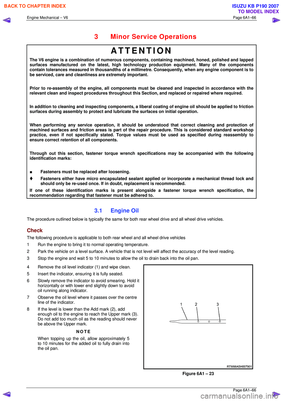
4 Remove the oil level indicator (1) and wipe clean.
5 Insert the indicator, ens uring it is fully seated.
6 Slowly remove the indicator to avoid smearing. Hold it horizontally or with lower end slightly down to avoid
oil running along indicator.
7 Observe the oil level where it passes over the centre
line of the indicator.
8 If the level is lower than the Add mark (2), add enough oil to the engine to reach the Upper mark (3).
Do not add too much oil as the reading should never
be above the Upper mark.
NOTE
When topping up the oil, allow approximately 5
to 10 minutes for the added oil to fully drain into
the oil pan.
Figure 6A1 – 23
BACK TO CHAPTER INDEX
TO MODEL INDEX
ISUZU KB P190 2007