Page 558 of 6020
4C1-54 FRONT WHEEL DRIVE
Important Operations
1. Bolt
Before removal, shift transfer lever into “2H” position and set
free wheeling hub knob into “FREE” position.
6. Hub nut
W rench : 5-8840-2 117-0
7. Hub and disc assembly
Before disassembly, remove the disc brake caliper assembly
and hang it on the frame with wires.
Refer to Section “Brake” for disc brake caliper removal
procedure.
14. Clutch Assembly
W hile pushing follower knob, turn clutch assembly clockwise
and then remove clutch assembly from knob.
19. Retaining Spring
Remove retaining spring from clutch assembly by turning it
counterclockwise.
BACK TO CHAPTER INDEX
TO MODEL INDEX
ISUZU KB P190 2007
Page 561 of 6020
FRONT WHEEL DRIVE 4C1-57
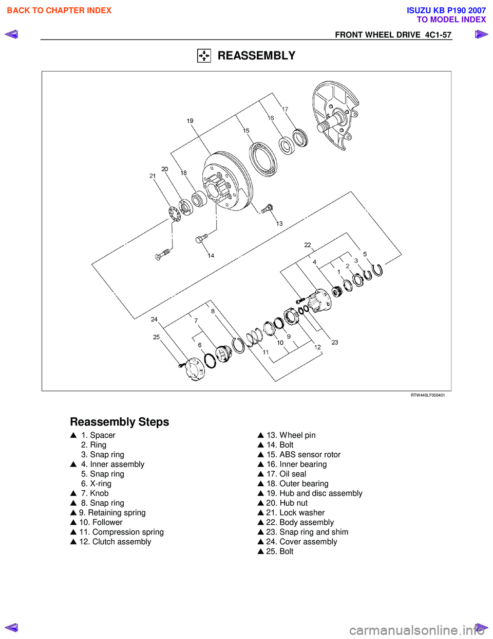
REASSEMBLY
RTW 440LF00040 1
Reassembly Steps
� 1 . Spacer
2. Ring
3. Snap ring
� 4. Inner assembly
5. Snap ring
6. X-ring
� 7. Knob
� 8. Snap ring
� 9. Retaining spring
� 1 0. Follower
� 11 . Compression spring
� 1 2. Clutch assembly
�
1 3. W heel pin
� 1 4. Bolt
� 1 5. ABS sensor rotor
� 1 6. Inner bearing
� 1 7. Oil seal
� 1 8. Outer bearing
� 1 9. Hub and disc assembly
� 20. Hub nut
� 21. Lock washer
� 22. Body assembly
� 23. Snap ring and shim
� 24. Cover assembly
� 25. Bolt
BACK TO CHAPTER INDEX
TO MODEL INDEX
ISUZU KB P190 2007
Page 562 of 6020

Amount o")
4C1-58 FRONT WHEEL DRIVE
Important Operations
1. Spacer
Apply grease to both faces of spacer.
4. Inner Assembly
Apply grease wheel bearing to inside face of ring.
g(oz)
Amount of grease 6 (0.21)
7. Knob
( 1 ) Apply grease W heel bearing to outer circumference of knob
and inner circumference of cover.
(2) Align detent ball to either groove of cover.
8. Snap Ring
Turn the smoother face to knob side.
9. Retaining Spring
Align the end of spring to the end of cut portion of clutch spring
groove.
10. Follower
Install follower to clutch so that follower nail will come closer to
the bent portion of retaining spring by aligning follower stopper
nail to outer teeth of clutch. Then, hook retaining spring onto
upper portion of hanger nails of follower.
11. Compression Spring
Turn the smaller diameter side to follower.
12. Clutch Assembly
Align follower nail to handle groove, and then assemble clutch
with knob by pushing and turning clutch counterclockwise to
knob.
BACK TO CHAPTER INDEX
TO MODEL INDEX
ISUZU KB P190 2007
Page 563 of 6020
FRONT WHEEL DRIVE 4C1-59
13. Wheel Pin
( 1 ) Place hub on a wood workbench or a block of wood,
approx. 6” by 6” to protect the wheel stud ends and threads.
(2) Install wheel stud using a hammer.
Be sure wheel stud is started squarely and seats completely.
(3) Align index marks and install hub to disc.
14. Bolt
Torque N ⋅m (kgf ⋅m/lb ⋅ft)
1 03 ( 10.5/76)
15. ABS sensor rotor
( 1 ) Set a new ABS sensor rotor, if replacement is required.
(2) Install the ABS sensor rotor in the hub, using special tools.
Installer : 5-8840-2789-0
Grip : 5-8840-0007-0
Refer to the section Brake.
16. Inner Bearing
Outer race ; outer bearing
Install the outer race by driving it into the hub.
Installer : 5-8840-2 119-0
Grip : 5-8840-0007-0
BACK TO CHAPTER INDEX
TO MODEL INDEX
ISUZU KB P190 2007
Page 565 of 6020
, then loosen
the nut to the full.
Tighten the hub nut at the value given below, us")
FRONT WHEEL DRIVE 4C1-61
Preload Adjustment
Tighten the hub nut at 29 N⋅m (3.0 kgf ⋅m / 22 lb ⋅ft), then loosen
the nut to the full.
Tighten the hub nut at the value given below, using a spring
scale on the wheel pin.
Bearing Preload N (kgf/lb)
New bearing and New oil seal 22 - 27
(2.2 - 2.8 / 4.9 - 6.2)
Used bearing and New oil seal 1
4 - 20
( 1 .4 - 2.0 / 3. 1 - 4.5)
If the measured bearing preload is outside the specifications,
adjust it by loosening or tightening the bearing nut.
21. Lock Washer
Turn the side with larger diameter of the tapered bore to the
vehicle outer side, and attach the washer.
If the bolt holes in the lock plate are not aligned with the
corresponding holes in the nut, reverse the lock plate.
If the bolt holes are still out of alignment, turn in the nut just
enough to obtain alignment,. Screw is to be fastened tightly so
its head may come lower than the surface of the washer.
22. Body Assembly
Apply adhesive (Loctite 5 15 or equivalent) to the both joining
faces.
23. Snap Ring and Shims
Adjust the clearance between the free wheeling hub body and
the snap ring.
Clearance mm(in) 0 - 0.2 (0 - 0.08)
Adjust Shims Available mm(in)
0.2, 0.3, 0.5, 1.0
(0.008, 0.0 11, 0.020, 0.039)
BACK TO CHAPTER INDEX
TO MODEL INDEX
ISUZU KB P190 2007
Page 579 of 6020
. REFER TO THE SRS
COMPONENT AND WIRING LOCATION VIEW IN
ORDER TO DETERMINE WH")
SHIFT ON THE FLY SYSTEM 4C2-1
SERVICE PRECAUTION
WARNING: THIS VEHICLE HAS A SUPPLEMENTAL
RESTRAINT SYSTEM (SRS). REFER TO THE SRS
COMPONENT AND WIRING LOCATION VIEW IN
ORDER TO DETERMINE WHETHER YOU ARE
PERFORMING SERVICE ON OR NEAR THE SRS
COMPONENTS OR THE SRS WIRING. WHEN YOU
ARE PERFORMING SERVICE ON OR NEAR THE
SRS COMPONENTS OR THE SRS WIRING, REFER
TO THE SRS SERVICE INFORMATION. FAILURE TO
FOLLOW WARNINGS COULD RESULT IN
POSSIBLE AIR BAG DEPLOYMENT, PERSONAL
INJURY, OR OTHERWISE UNNEEDED SRS SYSTEM
REPAIRS.
CAUTION: Always use the correct fastener in the
proper location. When you replace a fastener, use
ONLY the exact part number for that application.
ISUZU/GM will call out those fasteners that require
a replacement after removal. ISUZU/GM will also
call out the fasteners that require thread lockers o
r
thread sealant. UNLESS OTHERWISE SPECIFIED,
do not use supplemental coatings (Paints, greases,
or other corrosion inhibitors) on threaded fasteners
or fastener joint interfaces. Generally, such
coatings adversely affect the fastener torque and
the joint clamping force, and may damage the
fastener. When you install fasteners, use the
correct tightening sequence and specifications.
Following these instructions can help you avoid
damage to parts and systems.
BACK TO CHAPTER INDEX
TO MODEL INDEX
ISUZU KB P190 2007
Page 592 of 6020
BRAKE S 5
SECTI ON 5
BRAKE S
TA BLE OF CONTENTS
Section 5A Brake Control System ................................................................. ..................... 593
Section 5B Anti-Lock Brake System ................................................................................. 680
PAGE
BRAKES 5C-1
Sec
tion 5C Brakes .............................................................................................................. 700
PARKING BRAKE SYSTEM 5D-1
Section 5D Parking Brake System ............................................................................. ........ 770
TO MODEL INDEX
BACK TO MAIN INDEX
ISUZU KB P190 2007
Page 593 of 6020
 ................")
BRAKE CON TROL SY STE M 5 A
EHCU, Brake Pipe Diagram .......................................................................................... 5A-5
Hydraulic Unit (H/U) ...................................................................................................... 5A-6
Normal Braking ............................................................................................................. 5A- 7
Pressure Isolation (Pressure Maintain)....................................................................... 5A-8
Pressure Reduction ...................................................................................................... 5A-9
Brake Release ............................................................................................................... 5A -10
Circuit Diagram ............................................................................................................. 5A -11
Connector List ............................................................................................................... 5 A-14
Parts Location ............................................................................................................... 5 A-16
EHCU Pin-Assignment .................................................................................................. 5A-20
System Components .................................................................................................... 5A-22
Electronic Hydraulic Control Unit (EHCU).............................................................. 5A-22
ABS Warning Lamp .................................................................................................. 5A-22
Wheel Speed Sensor (WSS) .................................................................................... 5A-22
G Sensor ................................................................................................................... 5A- 22
Normal and Anti-lock Braking ................................................................................. 5A-22
Electronic Brake-force Distribution (EBD) System................................................ 5A-23
Brake Pedal Travel ................................................................................................... 5A-23
Acronyms and Abbreviations....................................................................................... 5A-23
General Diagnosis ............................................................................................................. 5A-23
General Information ...................................................................................................... 5A-23
ABS Service Precautions ............................................................................................. 5A-23
Computer System Service Precautions ...................................................................... 5A-24
General Service Precautions ....................................................................................... 5A-24
Note on Intermittents .................................................................................................... 5A-24
Test Driving ABS Complaint Vehicles ......................................................................... 5A-24
"ABS" Warning Lamp ................................................................................................... 5A-25
Normal Operation .......................................................................................................... 5A-2 5
SECTION 5A
BRAKE CONTROL SYSTEM
TABLE OF CONTENTS
Ser vice Precau tion ............................................................................................................ 5A -3
General Descrip tio n........................................................................................................... 5A -4
BACK TO CHAPTER INDEX
TO MODEL INDEX
ISUZU KB P190 2007

 Place hub on a wood workbench or a block of wood,
approx. 6” by 6” to protect the wheel stud ends and threads.
(2) Install wheel stud using a")
