Page 796 of 3061
AUTOMATIC BACK DOOR SYSTEM
BL-85
< SERVICE INFORMATION >
C
D
E
F
G
H
J
K
L
MA
B
BL
N
O
P
SchematicINFOID:0000000003532958
WIWA2049E
Page 797 of 3061
BL-86
< SERVICE INFORMATION >
AUTOMATIC BACK DOOR SYSTEM
Wiring Diagram - B/CLOS -
INFOID:0000000003532959
WIWA2050E
Page 798 of 3061
AUTOMATIC BACK DOOR SYSTEM
BL-87
< SERVICE INFORMATION >
C
D
E
F
G
H
J
K
L
MA
B
BL
N
O
P
WIWA0174E
Page 799 of 3061
BL-88
< SERVICE INFORMATION >
AUTOMATIC BACK DOOR SYSTEM
WIWA2051E
Page 800 of 3061
AUTOMATIC BACK DOOR SYSTEM
BL-89
< SERVICE INFORMATION >
C
D
E
F
G
H
J
K
L
MA
B
BL
N
O
P
WIWA2052E
Page 801 of 3061
BL-90
< SERVICE INFORMATION >
AUTOMATIC BACK DOOR SYSTEM
WIWA1317E
Page 802 of 3061

AUTOMATIC BACK DOOR SYSTEM
BL-91
< SERVICE INFORMATION >
C
D
E
F
G
H
J
K
L
MA
B
BL
N
O
P
Back Door Control Unit Harness Connector Terminal LayoutINFOID:0000000003532960
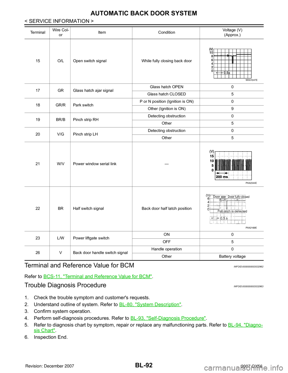
Terminal and Reference Value for Back Door Control UnitINFOID:0000000003532961
LIIA2444E
Te r m i n a l Wire Col-
orItem ConditionVoltage (V)
(Approx.)
1 B Ground — —
2 B Ground — —
3 Y/R Battery power supply — Battery voltage
4 G Hazard lamp output Request to flash hazards50ms > Pulse must be > 250ms
5 B/P Pinch strip ground — —
6 R Warning chime output Back door motor active Battery voltage
7 G/R Ignition switchIgnition switch ON Battery voltage
Ignition switch OFF 0
8 GR/B Back door close switchCLOSE position (ON) 0
NEUTRAL position (OFF) Battery voltage
9 L Warning chime ground — —
10 L/B Battery power supply — Battery voltage
11 Y Cinch latch motor CLOSE output Back door close operation Battery voltage
12 L Closure motor RETURN output Back door release operation Battery voltage
13 P/L Back door close switchCANCEL position 0
NEUTRAL position 5
14 P Close switch signal While fully opening back door
PIIA3278E
WIIA1047E
Page 803 of 3061

BL-92
< SERVICE INFORMATION >
AUTOMATIC BACK DOOR SYSTEM
Terminal and Reference Value for BCM
INFOID:0000000003532962
Refer to BCS-11, "Terminal and Reference Value for BCM".
Trouble Diagnosis ProcedureINFOID:0000000003532963
1. Check the trouble symptom and customer's requests.
2. Understand outline of system. Refer to BL-80, "
System Description".
3. Confirm system operation.
4. Perform self-diagnosis procedures. Refer to BL-93, "
Self-Diagnosis Procedure".
5. Refer to diagnosis chart by symptom, repair or replace any malfunctioning parts. Refer to BL-94, "
Diagno-
sis Chart".
6. Inspection End.
15 O/L Open switch signal While fully closing back door
17 GR Glass hatch ajar signalGlass hatch OPEN 0
Glass hatch CLOSED 5
18 GR/R Park switchP or N position (Ignition is ON) 0
Other (Ignition is ON) 9
19 BR/B Pinch strip RHDetecting obstruction 0
Other 5
20 V/G Pinch strip LHDetecting obstruction 0
Other 5
21 W/V Power window serial link —
22 BR Half switch signal Back door half latch position
23 L/W Power liftgate switchON 0
OFF 5
26 V Back door handle switch signalHandle operation 0
Other Battery voltage Te r m i n a l Wire Col-
orItem ConditionVoltage (V)
(Approx.)
WIIA1047E
PIIA2344E
PIIA2169E