2007 INFINITI QX56 sensor
[x] Cancel search: sensorPage 1593 of 3061
EC-510
< SERVICE INFORMATION >
DTC P1564 ICC STEERING SWITCH
Diagnosis Procedure
INFOID:0000000003532044
1.CHECK GROUND CONNECTIONS
1. Turn ignition switch OFF.
2. Loosen and retighten three ground screws on the body.
Refer to EC-143, "
Ground Inspection".
OK or NG
OK >> GO TO 2.
NG >> Repair or replace ground connections.
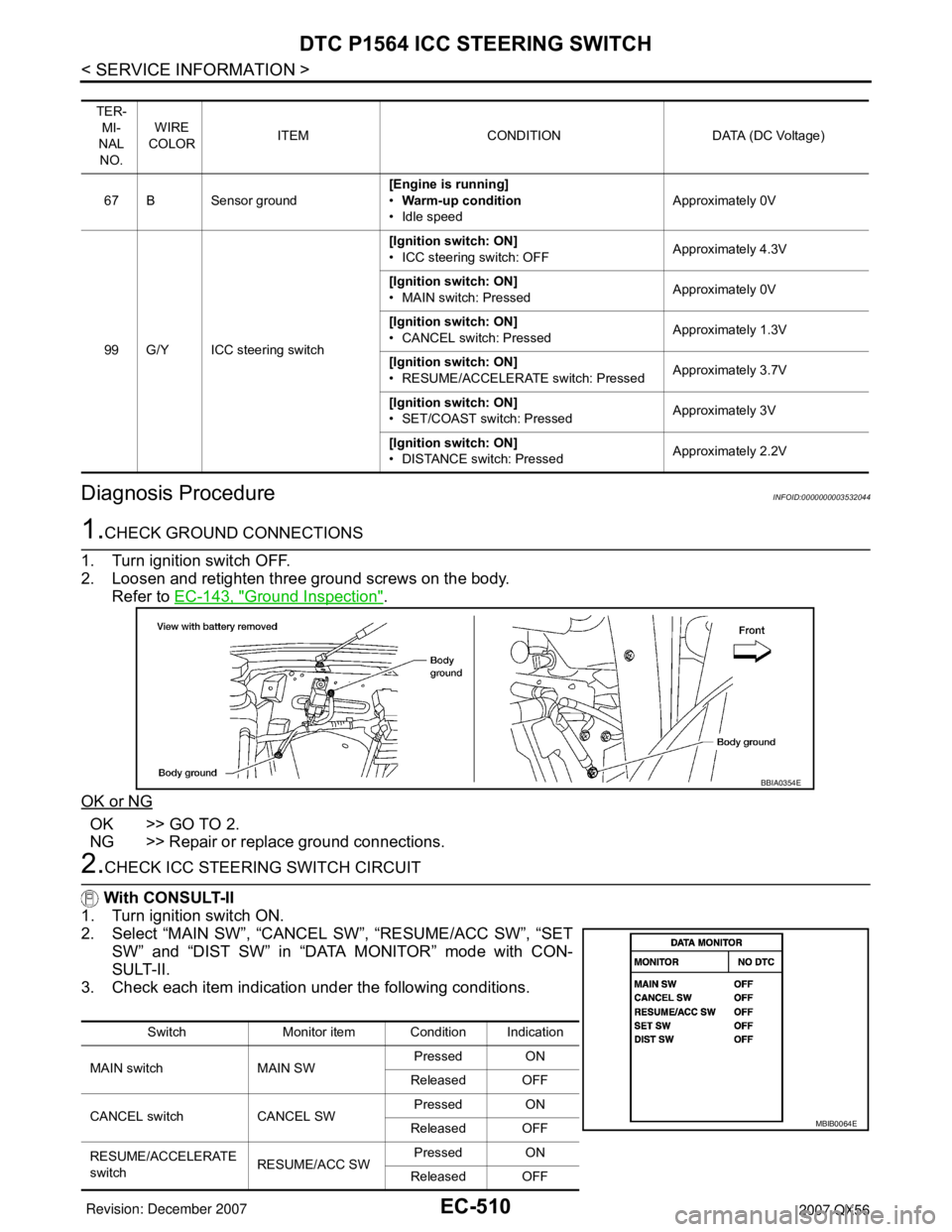
2.CHECK ICC STEERING SWITCH CIRCUIT
With CONSULT-II
1. Turn ignition switch ON.
2. Select “MAIN SW”, “CANCEL SW”, “RESUME/ACC SW”, “SET
SW” and “DIST SW” in “DATA MONITOR” mode with CON-
SULT-II.
3. Check each item indication under the following conditions.
TER-
MI-
NAL
NO.WIRE
COLORITEM CONDITION DATA (DC Voltage)
67 B Sensor ground[Engine is running]
•Warm-up condition
• Idle speedApproximately 0V
99 G/Y ICC steering switch[Ignition switch: ON]
• ICC steering switch: OFFApproximately 4.3V
[Ignition switch: ON]
• MAIN switch: PressedApproximately 0V
[Ignition switch: ON]
• CANCEL switch: PressedApproximately 1.3V
[Ignition switch: ON]
• RESUME/ACCELERATE switch: PressedApproximately 3.7V
[Ignition switch: ON]
• SET/COAST switch: PressedApproximately 3V
[Ignition switch: ON]
• DISTANCE switch: PressedApproximately 2.2V
BBIA0354E
Switch Monitor item Condition Indication
MAIN switch MAIN SWPressed ON
Released OFF
CANCEL switch CANCEL SWPressed ON
Released OFF
RESUME/ACCELERATE
switchRESUME/ACC SWPressed ON
Released OFF
MBIB0064E
Page 1599 of 3061
EC-516
< SERVICE INFORMATION >
DTC P1564 ASCD STEERING SWITCH
Diagnosis Procedure
INFOID:0000000003532051
1.CHECK GROUND CONNECTIONS
1. Turn ignition switch OFF.
2. Loosen and retighten three ground screws on the body.
Refer to EC-143, "
Ground Inspection".
OK or NG
OK >> GO TO 2.
NG >> Repair or replace ground connections.
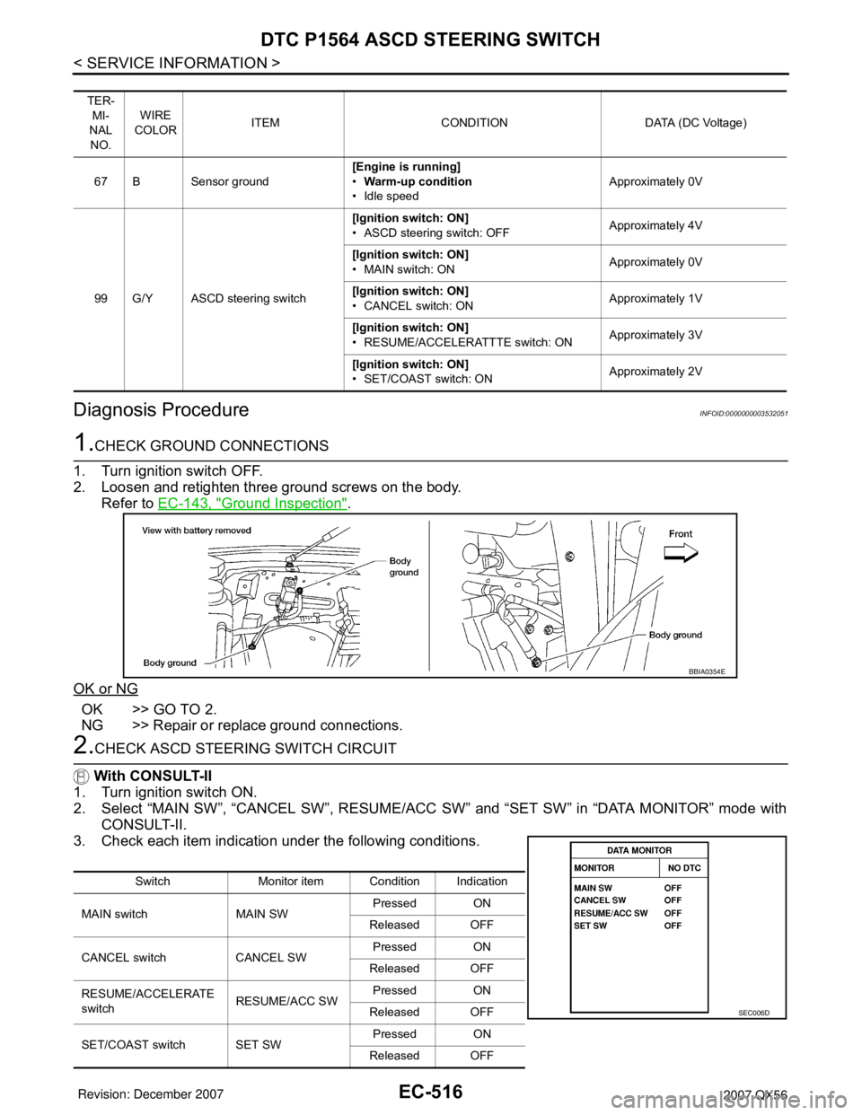
2.CHECK ASCD STEERING SWITCH CIRCUIT
With CONSULT-II
1. Turn ignition switch ON.
2. Select “MAIN SW”, “CANCEL SW”, RESUME/ACC SW” and “SET SW” in “DATA MONITOR” mode with
CONSULT-II.
3. Check each item indication under the following conditions.
TER-
MI-
NAL
NO.WIRE
COLORITEM CONDITION DATA (DC Voltage)
67 B Sensor ground[Engine is running]
•Warm-up condition
• Idle speedApproximately 0V
99 G/Y ASCD steering switch[Ignition switch: ON]
• ASCD steering switch: OFFApproximately 4V
[Ignition switch: ON]
• MAIN switch: ONApproximately 0V
[Ignition switch: ON]
• CANCEL switch: ONApproximately 1V
[Ignition switch: ON]
• RESUME/ACCELERATTTE switch: ONApproximately 3V
[Ignition switch: ON]
• SET/COAST switch: ONApproximately 2V
BBIA0354E
Switch Monitor item Condition Indication
MAIN switch MAIN SWPressed ON
Released OFF
CANCEL switch CANCEL SWPressed ON
Released OFF
RESUME/ACCELERATE
switchRESUME/ACC SWPressed ON
Released OFF
SET/COAST switch SET SWPressed ON
Released OFF
SEC006D
Page 1618 of 3061
DTC P1574 ICC VEHICLE SPEED SENSOR
EC-535
< SERVICE INFORMATION >
C
D
E
F
G
H
I
J
K
L
MA
EC
N
P O
DTC P1574 ICC VEHICLE SPEED SENSOR
Component DescriptionINFOID:0000000003532070
The ECM receives two vehicle speed signals via CAN communication line. One is sent from “unified meter and
A/C amp.”, and the other is from TCM (Transmission control module). The ECM uses these signals for ICC
control. Refer to ACS-6
for ICC functions.
On Board Diagnosis LogicINFOID:0000000003532071
•This self-diagnosis has the one trip detection logic.
•The MIL will not light up for this self-diagnosis.
NOTE:
•If DTC P1574 is displayed with DTC U1000, U1001, first perform the trouble diagnosis for DTC U1000,
U1001. Refer to EC-145
.
•If DTC P1574 is displayed with DTC U1010, first perform the trouble diagnosis for DTC U1010. Refer
to EC-147
.
•If DTC P1574 is displayed with DTC P0500, first perform the trouble diagnosis for DTC P0500. Refer
to EC-429
.
•If DTC P1574 is displayed with DTC P0605, first perform the trouble diagnosis for DTC P0605. Refer
to EC-444
.
DTC Confirmation ProcedureINFOID:0000000003532072
CAUTION:
Always drive vehicle at a safe speed.
NOTE:
If DTC Confirmation Procedure has been previously conducted, always turn ignition switch OFF and wait at
least 10 seconds before conducting the next test.
TESTING CONDITION:
Step 3 may be conducted with the drive wheels lifted in the shop or by driving the vehicle. If a road test
is expected to be easier, it is unnecessary to lift the vehicle.
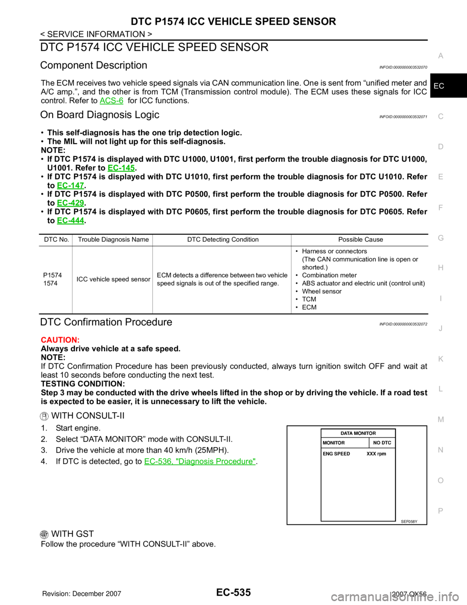
WITH CONSULT-II
1. Start engine.
2. Select “DATA MONITOR” mode with CONSULT-II.
3. Drive the vehicle at more than 40 km/h (25MPH).
4. If DTC is detected, go to EC-536, "
Diagnosis Procedure".
WITH GST
Follow the procedure “WITH CONSULT-II” above.
DTC No. Trouble Diagnosis Name DTC Detecting Condition Possible Cause
P1574
1574ICC vehicle speed sensorECM detects a difference between two vehicle
speed signals is out of the specified range.• Harness or connectors
(The CAN communication line is open or
shorted.)
• Combination meter
• ABS actuator and electric unit (control unit)
• Wheel sensor
•TCM
•ECM
SEF058Y
Page 1619 of 3061
EC-536
< SERVICE INFORMATION >
DTC P1574 ICC VEHICLE SPEED SENSOR
Diagnosis Procedure
INFOID:0000000003532073
1.CHECK DTC WITH TCM
Check DTC with TCM. Refer to AT-39, "
OBD-II Diagnostic Trouble Code (DTC)".
OK or NG
OK >> GO TO 2.
NG >> Perform trouble shooting relevant to DTC indicated.
2.CHECK DTC WITH “ABS ACTUATOR AND ELECTRIC UNIT (CONTROL UNIT)”
Refer to BRC-11
.
OK or NG
OK >> GO TO 3.
NG >> Repair or replace.
3.CHECK COMBINATION METER FUNCTION
Refer to DI-5
.
>>INSPECTION END
Page 1620 of 3061
DTC P1574 ASCD VEHICLE SPEED SENSOR
EC-537
< SERVICE INFORMATION >
C
D
E
F
G
H
I
J
K
L
MA
EC
N
P O
DTC P1574 ASCD VEHICLE SPEED SENSOR
Component DescriptionINFOID:0000000003532074
The ECM receives two vehicle speed sensor signals via CAN communication line. One is sent from combina-
tion meter and the other is from TCM (Transmission control module). The ECM uses these signals for ASCD
control. Refer to EC-30
for ASCD functions.
On Board Diagnosis LogicINFOID:0000000003532075
•This self-diagnosis has the one trip detection logic.
•The MIL will not light up for this self-diagnosis.
NOTE:
•If DTC P1574 is displayed with DTC U1000, U1001, first perform the trouble diagnosis for DTC U1000,
U1001. Refer to EC-145
.
•If DTC P1574 is displayed with DTC U1010, first perform the trouble diagnosis for DTC U1010. Refer
to EC-147
.
•If DTC P1574 is displayed with DTC P0500, first perform the trouble diagnosis for DTC P0500. Refer
to EC-429
.
•If DTC P1574 is displayed with DTC P0605, first perform the trouble diagnosis for DTC P0605. Refer
to EC-444
.
DTC Confirmation ProcedureINFOID:0000000003532076
CAUTION:
Always drive vehicle at a safe speed.
NOTE:
If DTC Confirmation Procedure has been previously conducted, always turn ignition switch OFF and wait at
least 10 seconds before conducting the next test.
TESTING CONDITION:
Step 3 may be conducted with the drive wheels lifted in the shop or by driving the vehicle. If a road test
is expected to be easier, it is unnecessary to lift the vehicle.
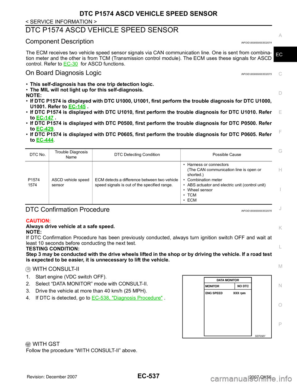
WITH CONSULT-II
1. Start engine (VDC switch OFF).
2. Select “DATA MONITOR” mode with CONSULT-II.
3. Drive the vehicle at more than 40 km/h (25 MPH).
4. If DTC is detected, go to EC-538, "
Diagnosis Procedure" .
WITH GST
Follow the procedure “WITH CONSULT-II” above.
DTC No.Trouble Diagnosis
NameDTC Detecting Condition Possible Cause
P1574
1574ASCD vehicle speed
sensorECM detects a difference between two vehicle
speed signals is out of the specified range.• Harness or connectors
(The CAN communication line is open or
shorted.)
• Combination meter
• ABS actuator and electric unit (control unit)
• Wheel sensor
•TCM
•ECM
SEF058Y
Page 1621 of 3061
EC-538
< SERVICE INFORMATION >
DTC P1574 ASCD VEHICLE SPEED SENSOR
Diagnosis Procedure
INFOID:0000000003532077
1.CHECK DTC WITH TCM
Check DTC with TCM. Refer to AT-39, "
OBD-II Diagnostic Trouble Code (DTC)".
OK or NG
OK >> GO TO 2.
NG >> Perform trouble shooting relevant to DTC indicated.
2.CHECK DTC WITH ABS ACTUATOR AND ELECTRIC UNIT (CONTROL UNIT)
Refer to BRC-11
.
OK or NG
OK >> GO TO 3.
NG >> Repair or replace.
3.CHECK COMBINATION METER FUNCTION
Check combination meter function.
Refer to DI-5
.
>>INSPECTION END
Page 1631 of 3061
EC-548
< SERVICE INFORMATION >
DTC P2101 ELECTRIC THROTTLE CONTROL FUNCTION
DTC P2101 ELECTRIC THROTTLE CONTROL FUNCTION
DescriptionINFOID:0000000003532091
NOTE:
If DTC P2101 is displayed with DTC P2100 or 2119, first perform the trouble diagnosis for DTC P2100
or P2119. Refer to EC-543
or EC-559 .
Electric throttle control actuator consists of throttle control motor, throttle position sensor, etc.
The throttle control motor is operated by the ECM and it opens and closes the throttle valve.
The current opening angle of the throttle valve is detected by the throttle position sensor and it provides feed-
back to the ECM to control the throttle control motor to make the throttle valve opening angle properly in
response to driving condition.
On Board Diagnosis LogicINFOID:0000000003532092
This self-diagnosis has the one trip detection logic.
FA I L - S A F E M O D E
When the malfunction is detected, ECM enters fail-safe mode and the MIL lights up.
DTC Confirmation ProcedureINFOID:0000000003532093
NOTE:
If DTC Confirmation Procedure has been previously conducted, always turn ignition switch OFF and wait at
least 10 seconds before conducting the next test.
TESTING CONDITION:
Before performing the following procedure, confirm that battery voltage is more than 11V when engine
is running.
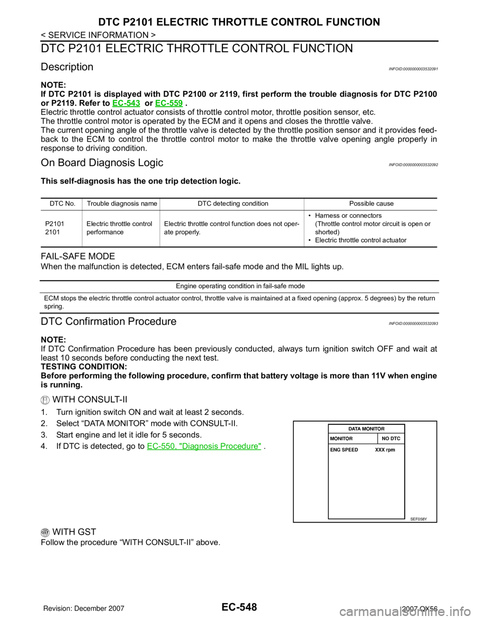
WITH CONSULT-II
1. Turn ignition switch ON and wait at least 2 seconds.
2. Select “DATA MONITOR” mode with CONSULT-II.
3. Start engine and let it idle for 5 seconds.
4. If DTC is detected, go to EC-550, "
Diagnosis Procedure" .
WITH GST
Follow the procedure “WITH CONSULT-II” above.
DTC No. Trouble diagnosis name DTC detecting condition Possible cause
P2101
2101Electric throttle control
performanceElectric throttle control function does not oper-
ate properly.• Harness or connectors
(Throttle control motor circuit is open or
shorted)
• Electric throttle control actuator
Engine operating condition in fail-safe mode
ECM stops the electric throttle control actuator control, throttle valve is maintained at a fixed opening (approx. 5 degrees) by the return
spring.
SEF058Y
Page 1637 of 3061
EC-554
< SERVICE INFORMATION >
DTC P2118 THROTTLE CONTROL MOTOR
DTC P2118 THROTTLE CONTROL MOTOR
Component DescriptionINFOID:0000000003532098
The throttle control motor is operated by the ECM and it opens and closes the throttle valve.
The current opening angle of the throttle valve is detected by the throttle position sensor and it provides feed-
back to the ECM to control the throttle control motor to make the throttle valve opening angle properly in
response to driving condition.
On Board Diagnosis LogicINFOID:0000000003532099
This self-diagnosis has the one trip detection logic.
FA I L - S A F E M O D E
When the malfunction is detected, the ECM enters fail-safe mode and the MIL lights up.
DTC Confirmation ProcedureINFOID:0000000003532100
NOTE:
If DTC Confirmation Procedure has been previously conducted, always turn ignition switch OFF and wait at
least 10 seconds before conducting the next test.
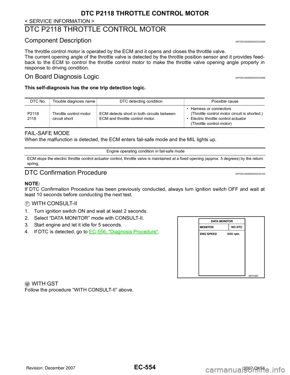
WITH CONSULT-II
1. Turn ignition switch ON and wait at least 2 seconds.
2. Select “DATA MONITOR” mode with CONSULT-II.
3. Start engine and let it idle for 5 seconds.
4. If DTC is detected, go to EC-556, "
Diagnosis Procedure".
WITH GST
Follow the procedure “WITH CONSULT-II” above.
DTC No. Trouble diagnosis name DTC detecting condition Possible cause
P2118
2118Throttle control motor
circuit shortECM detects short in both circuits between
ECM and throttle control motor.• Harness or connectors
(Throttle control motor circuit is shorted.)
• Electric throttle control actuator
(Throttle control motor)
Engine operating condition in fail-safe mode
ECM stops the electric throttle control actuator control, throttle valve is maintained at a fixed opening (approx. 5 degrees) by the return
spring.
SEF058Y