2007 INFINITI QX56 Rear brake
[x] Cancel search: Rear brakePage 1179 of 3061

EC-96
< SERVICE INFORMATION >
TROUBLE DIAGNOSIS
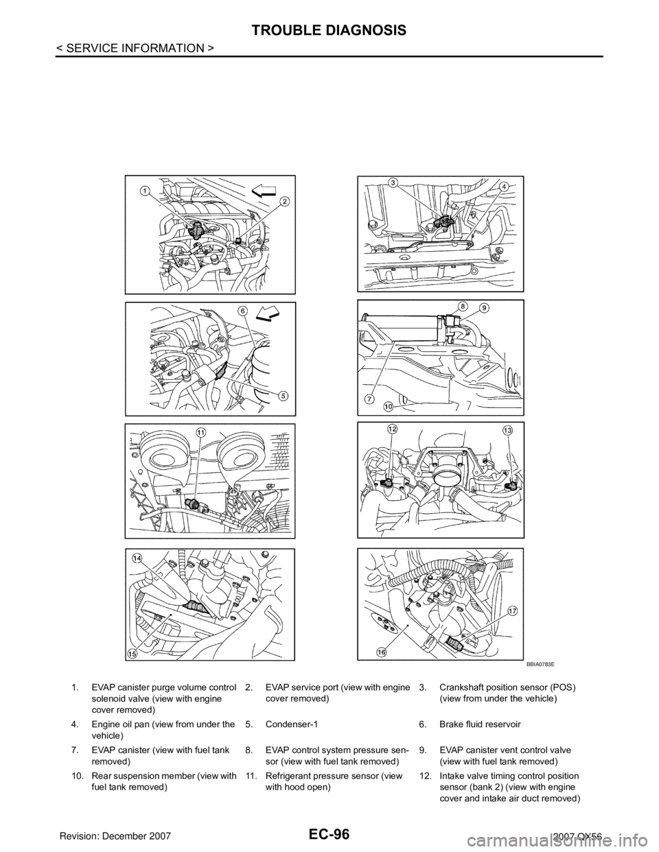
1. EVAP canister purge volume control
solenoid valve (view with engine
cover removed)2. EVAP service port (view with engine
cover removed)3. Crankshaft position sensor (POS)
(view from under the vehicle)
4. Engine oil pan (view from under the
vehicle)5. Condenser-1 6. Brake fluid reservoir
7. EVAP canister (view with fuel tank
removed)8. EVAP control system pressure sen-
sor (view with fuel tank removed)9. EVAP canister vent control valve
(view with fuel tank removed)
10. Rear suspension member (view with
fuel tank removed)11. Refrigerant pressure sensor (view
with hood open)12. Intake valve timing control position
sensor (bank 2) (view with engine
cover and intake air duct removed)
BBIA0783E
Page 1199 of 3061
![INFINITI QX56 2007 Factory Service Manual EC-116
< SERVICE INFORMATION >
TROUBLE DIAGNOSIS
FUEL T/TMP SE
[°C] or [°F]ו The fuel temperature (determined by the
signal voltage of the fuel tank tempera-
ture sensor) is displayed.
INT/A T INFINITI QX56 2007 Factory Service Manual EC-116
< SERVICE INFORMATION >
TROUBLE DIAGNOSIS
FUEL T/TMP SE
[°C] or [°F]ו The fuel temperature (determined by the
signal voltage of the fuel tank tempera-
ture sensor) is displayed.
INT/A T](/manual-img/42/57029/w960_57029-1198.png)
EC-116
< SERVICE INFORMATION >
TROUBLE DIAGNOSIS
FUEL T/TMP SE
[°C] or [°F]ו The fuel temperature (determined by the
signal voltage of the fuel tank tempera-
ture sensor) is displayed.
INT/A TEMP SE
[°C] or [°F]×ו The intake air temperature (determined
by the signal voltage of the intake air
temperature sensor) is indicated.
EVAP SYS PRES
[V]ו The signal voltage of EVAP control sys-
tem pressure sensor is displayed.
FUEL LEVEL SE [V]ו The signal voltage of the fuel level sen-
sor is displayed.
START SIGNAL
[ON/OFF]×ו Indicates start signal status [ON/OFF]
computed by the ECM according to the
signals of engine speed and battery volt-
age.• After starting the engine, [OFF] is dis-
played regardless of the starter signal.
CLSD THL POS
[ON/OFF]×ו Indicates idle position [ON/OFF] comput-
ed by ECM according to the accelerator
pedal position sensor signal.
AIR COND SIG
[ON/OFF]×ו Indicates [ON/OFF] condition of the air
conditioner switch as determined by the
air conditioner signal.
P/N POSI SW
[ON/OFF]×ו Indicates [ON/OFF] condition from the
park/neutral position (PNP) switch sig-
nal.
PW/ST SIGNAL
[ON/OFF]×ו [ON/OFF] condition of the power steering
system (determined by the signal voltage
of the power steering pressure sensor
signal) is indicated.
LOAD SIGNAL [ON/
OFF]×ו Indicates [ON/OFF] condition from the
electrical load signal.
ON: Rear window defogger switch is ON
and/or lighting switch is in 2nd position.
OFF: Both rear window defogger switch
and lighting switch are OFF.
IGNITION SW
[ON/OFF]ו Indicates [ON/OFF] condition from igni-
tion switch signal.
HEATER FAN SW
[ON/OFF]ו Indicates [ON/OFF] condition from heat-
er fan switch signal.
BRAKE SW
[ON/OFF]ו Indicates [ON/OFF] condition from the
stop lamp switch signal.
INJ PULSE-B1
[msec]×
• Indicates the actual fuel injection pulse
width compensated by ECM according to
the input signals.• When the engine is stopped, a certain
computed value is indicated.
INJ PULSE-B2
[msec]
IGN TIMING [BT-
DC]ו Indicates the ignition timing computed by
ECM according to the input signals.• When the engine is stopped, a certain
value is indicated.
CAL/LD VALUE [%]• “Calculated load value” indicates the val-
ue of the current air flow divided by peak
air flow.
MASS AIRFLOW
[g·m/s]• Indicates the mass air flow computed by
ECM according to the signal voltage of
the mass air flow sensor. Monitored item
[Unit]ECM IN-
PUT SIG-
NALSMAIN
SIGNALSDescription Remarks
Page 1208 of 3061

TROUBLE DIAGNOSIS
EC-125
< SERVICE INFORMATION >
C
D
E
F
G
H
I
J
K
L
MA
EC
N
P O
AIR COND SIG• Engine: After warming up, idle the
engineAir conditioner switch: OFF OFF
Air conditioner switch: ON
(Compressor operates.)ON
P/N POSI SW • Ignition switch: ONSelector lever: P or N ON
Selector lever: Except above OFF
PW/ST SIGNAL• Engine: After warming up, idle the
engineSteering wheel: Not being turned
(Forward direction)OFF
Steering wheel: Being turned ON
LOAD SIGNAL • Ignition switch: ONRear window defogger switch is ON
and/or lighting switch is in 2nd.ON
Rear window defogger switch is OFF
and lighting switch is OFF.OFF
IGNITION SW • Ignition switch: ON → OFF → ON ON → OFF → ON
HEATER FAN SW• Engine: After warming up, idle the
engineHeater fan control switch: ON ON
Heater fan control switch: OFF OFF
BRAKE SW • Ignition switch: ONBrake pedal: Fully released OFF
Brake pedal: Slightly depressed ON
INJ PULSE-B1
INJ PULSE-B2• Engine: After warming up
• Selector lever: P or N
• Air conditioner switch: OFF
• No loadIdle 2.0 - 2.8 msec
2,000 rpm 1.9 - 2.9 msec
IGN TIMING• Engine: After warming up
• Selector lever: P or N
• Air conditioner switch: OFF
• No loadIdle 10° - 20° BTDC
2,000 rpm 25° - 45° BTDC
CAL/LD VALUE• Engine: After warming up
• Selector lever: P or N
• Air conditioner switch: OFF
• No loadIdle 14% - 33%
2,500 rpm 12% - 25%
MASS AIRFLOW• Engine: After warming up
• Selector lever: P or N
• Air conditioner switch: OFF
• No loadIdle 3.0 - 9.0 g·m/s
2,500 rpm 9.0 - 28.0 g·m/s
PURG VOL C/V• Engine: After warming up
• Selector lever: P or N
• Air conditioner switch: OFF
• No loadIdle
(Accelerator pedal: Not depressed
even slightly, after engine starting.)0%
2,000 rpm —
INT/V TIM (B1)
INT/V TIM (B2)• Engine: After warming up
• Selector lever: P or N
• Air conditioner switch: OFF
• No loadIdle−5° - 5°CA
2,000 rpm Approx. 0° - 20°CA
INT/V SOL (B1)
INT/V SOL (B2)• Engine: After warming up
• Selector lever: P or N
• Air conditioner switch: OFF
• No loadIdle 0% - 2%
2,000 rpm Approx. 25% - 50%
AIR COND RLY• Engine: After warming up, idle the
engineAir conditioner switch: OFF OFF
Air conditioner switch: ON
(Compressor: Operates)ON
FUEL PUMP RLY• For 1 second after turning ignition switch ON
• Engine running or crankingON
• Except above conditions OFF
VENT CONT/V • Ignition switch: ON OFF
THRTL RELAY • Ignition switch: ON ONMONITOR ITEM CONDITION SPECIFICATION
Page 2009 of 3061

TOW TRUCK TOWING
GI-43
< SERVICE INFORMATION >
C
D
E
F
G
H
I
J
K
L
MB
GI
N
O
P
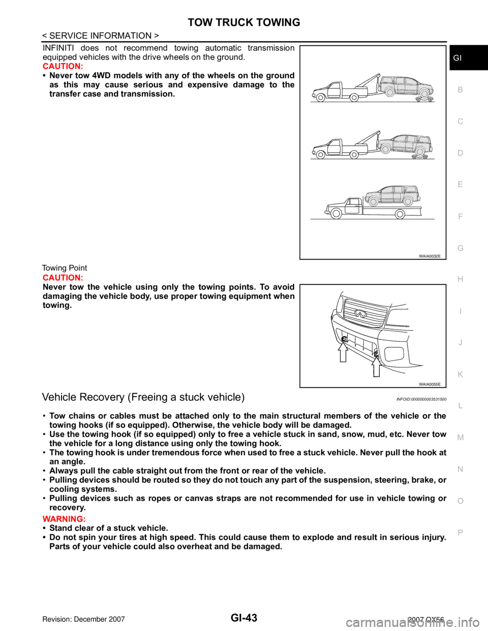
INFINITI does not recommend towing automatic transmission
equipped vehicles with the drive wheels on the ground.
CAUTION:
• Never tow 4WD models with any of the wheels on the ground
as this may cause serious and expensive damage to the
transfer case and transmission.
Towing Point
CAUTION:
Never tow the vehicle using only the towing points. To avoid
damaging the vehicle body, use proper towing equipment when
towing.
Vehicle Recovery (Freeing a stuck vehicle)INFOID:0000000003531500
•Tow chains or cables must be attached only to the main structural members of the vehicle or the
towing hooks (if so equipped). Otherwise, the vehicle body will be damaged.
•Use the towing hook (if so equipped) only to free a vehicle stuck in sand, snow, mud, etc. Never tow
the vehicle for a long distance using only the towing hook.
•The towing hook is under tremendous force when used to free a stuck vehicle. Never pull the hook at
an angle.
•Always pull the cable straight out from the front or rear of the vehicle.
•Pulling devices should be routed so they do not touch any part of the suspension, steering, brake, or
cooling systems.
•Pulling devices such as ropes or canvas straps are not recommended for use in vehicle towing or
recovery.
WARNING:
• Stand clear of a stuck vehicle.
• Do not spin your tires at high speed. This could cause them to explode and result in serious injury.
Parts of your vehicle could also overheat and be damaged.
WAIA0032E
WAIA0055E
Page 2107 of 3061

IDX-3
A
C
D
E
F
G
H
I
J
K
L B
IDX
ALPHABETICAL INDEX
Brake fluid level ................................................. MA-28
Brake hydraulic line ........................................... BR-12
Brake inspection ................................................ MA-28
Brake lines and cables inspection ..................... MA-28
Brake master cylinder ....................................... BR-15
Brake switch ...................................... EC-572, EC-584
BRK/SW - Wiring diagram ............................... EC-585
Bulb specifications ........................................... LT-148
Bumper, front ...................................................... EI-13
Bumper, rear ....................................................... EI-15
C
Cabin air filter .................................................... MA-21
Camshaft ........................................................... EM-46
Camshaft inspection .......................................... EM-49
Camshaft position sensor (PHASE) ................ EC-369
CAN - Wiring diagram .............. EC-157, AT-93, AT-94
CAN communication EC-32, EC-156, EC-159, TF-112,
RSU-6
Canister-See EVAP canister ............................. EC-36
Center case (Transfer) ....................... TF-154, TF-167
CHARGE - Wiring diagram ............................... SC-19
Charging system ............................................... SC-17
Chassis and body maintenance ........................ MA-21
Chassis and body maintenanceSchedule 1 ........ MA-8
Chassis and body maintenanceSchedule 2 ...... MA-10
CHIME - Wiring diagram ..................................... DI-41
Circuit breaker ................................................... PG-17
Clock ................................................................... DI-61
CLOCK - Wiring diagram .................................... DI-61
Closed loop control ............................. EC-26, EC-501
Closed loop control (Bank 1) ........................... EC-501
Closed loop control (Bank 2) ........................... EC-501
Clutch drum (Transfer) ....................... TF-154, TF-167
Clutch pressure switch (Transfer) ...... TF-154, TF-167
Coil spring (front) ............................................. FSU-10
Collision diagnosis .......................................... SRS-53
Combination lamp, front, removal and installation . LT-
25
Combination lamp, rear, removal and installation .. LT-
101
Combination meter ................................................ DI-5
Combination switch ............................................ LT-79
COMBSW - Wiring diagram ............................... LT-79
COMM - Wiring diagram ................................... AV-94
COMPAS - Wiring diagram ................................. DI-24
Compass ............................................................. DI-23
Component Location (auto A/C) ...................... ATC-38
Compressor clutch removal and installation . ATC-180
Compressor mounting ................................... ATC-179
Compressor precaution ................................... ATC-11
Compressor special service tool ..................... ATC-14
Condenser ..................................................... ATC-184
Connecting rod .................................................. EM-96
Connecting rod bearing clearance .................... EM-96
Connecting rod bushing clearance .................... EM-96
Console box - See Instrument panel ................... IP-10
CONSULT for VDC ......................................... BRC-27
CONSULT general information ........................... GI-37
CONSULT-II for engine ................................... EC-118
Control units (terminal arrangement) ................. PG-71
Control valve (A/T) ............................................. AT-36
Control valve (Transfer) ...................... TF-154, TF-167
Converter housing installation ............ AT-240, AT-244
COOL/F - Wiring diagram ................................ EC-507
Coolant mixture ratio ......................................... MA-12
Coolant replacement ............................ CO-10, MA-13
Cooling circuit (engine) ........................................ CO-8
Cooling fan ........................................................ CO-17
Cooling fan control ........................................... EC-504
Cooling fan motor ............................................ EC-513
Cooling unit (A/C evaporator) ....... ATC-157, ATC-186
Corrosion protection ......................................... BL-157
Crankcase ventilation system - See Positive crankcase
ventilation .......................................................... EC-46
Crankshaft ......................................................... EM-79
Crankshaft position sensor (POS) ................... EC-362
Crash zone sensor .......................................... SRS-48
CUR/SE - Wiring diagram ... EC-522, EC-529, EC-536,
EC-543
Cylinder block .................................................... EM-78
Cylinder block boring ......................................... EM-99
D
D/LOCK - Wiring diagram ................................... BL-19
Data link connector for Consult ......... EC-120, EC-132
Daytime light system .......................................... LT-27
Daytime running light - See Daytime light system .. LT-
27
DEF - Wiring diagram ....................................... GW-74
Diagnosis sensor unit ...................................... SRS-51
Diagnostic trouble code (DTC) for OBD system . EC-9,
EC-54
Diagnostic trouble code (DTC) inspection priority chart
EC-91
Differential carrier assembly ............................ RFD-15
Differential gear oil replacement ........................ MA-26
Dimensions ......................................................... GI-51
Direct clutch solenoid valve ................ AT-143, AT-145
Display and amp.assembly .............................. ATC-59
Display Control Unit ........................................... AV-83
Display Unit ....................................................... AV-83
Dome light - See Interior lamp .......................... LT-110
Door glass .......................................... GW-62, GW-65
Door lock .......................................................... BL-121
Door mirror lamp ............................................... LT-110
Door trim .............................................................. EI-32
Door, front ........................................... BL-117, GW-62
Door, rear ........................................... BL-117, GW-65
Drive belt ........................................................... EM-13
Drive chain (Transfer) ......................... TF-149, TF-176
Drive pinion diff. inspection .............................. RFD-18
Drive shaft (rear) ................................................ RAX-7
Driver air bag ................................................... SRS-39
DTC work support ............................................ EC-128
DTRL - Wiring diagram ....................................... LT-31
Page 2112 of 3061

IDX-8
ALPHABETICAL INDEX
Three way catalyst ............................................ EM-21
Three way catalyst function (Bank 1) ............... EC-376
Three way catalyst function (Bank 2) ............... EC-376
Three way catalyst precautions ............................ GI-5
Throttle control motor ....................................... EC-601
Throttle control motor relay .............................. EC-589
Throttle position sensor (TPS) .. EC-224, EC-343, EC-
514, EC-516, EC-621
Throttle valve closed position learning ............... EC-80
Tie-rod ............................................................... PS-15
Timing chain ..................................................... EM-37
Tire rotation ....................................................... MA-28
Tire size .............................................................. GI-51
Torque converter installation AT-239, AT-240, AT-243,
AT-244
Torque convertor clutch solenoid valve ... AT-114, AT-
116
Tow truck towing ................................................. GI-44
Towing point ....................................................... GI-45
TPS1 - Wiring diagram .................................... EC-345
TPS2 - Wiring diagram .................................... EC-226
TPS3 - Wiring diagram .................................... EC-623
Traction control system - Wiring diagram ....... BRC-16
Transfer control device ............. TF-75, TF-79, TF-138
Transfer control unit inspection table ................. TF-35
Transfer dropping resistor .................................. TF-89
Transfer fluid temperature sensor TF-103, TF-154, TF-
167
Transfer motor .................................... TF-101, TF-142
Transfer motor relay ........................................ TF-101
Transfer oil replacement ................................... MA-24
Transfer serial number ........................................ GI-50
Transmission serial number ................................ GI-50
Tread-FR&RR (Dimensions) ............................... GI-51
Trim ..................................................................... EI-35
TRNSCV - Wiring diagram .................. BL-130, BL-146
Trouble diagnoses .............................................. GI-11
Turbine revolution sensor ................................ AT-105
TURN - Wiring diagram ...................................... LT-67
Turn signal lamp ................................................. LT-63
Two trip detection logic ...................................... EC-49
Two-pole lift ........................................................ GI-43
V
Vacuum hose (brake system) ............................ BR-20
Vacuum hose drawing (Engine control) ........... EC-106
Valve clearance ................................................ EM-55
Valve guide ....................................................... EM-69
Vanity mirror lamp ............................................. LT-110
VDC (vehicle dynamics control) ........................ BRC-7
VDC -Wiring diagram ...................................... BRC-16
Vehicle identification number .............................. GI-49
Vehicle recovery (freeing a stuck vehicle) .......... GI-45
Vehicle security (theft warning) system ............. BL-67
Vehicle speed sensor (VSS) ............................ EC-464
VEHSEC - Wiring diagram ................................. BL-71
VENT/V - Wiring diagram .................. EC-412, EC-419
VIN registration .................................................. EC-79
Viscosity number (SAE) .................................... MA-12
VSS A/T - Wiring diagram .................. AT-107, AT-109
W
W/ANT - Wiring diagram .................................... AV-59
Wait detection switch ......................................... TF-68
WARN - Wiring diagram ...................................... DI-29
Warning chime .................................................... DI-38
Warning lamps .................................................... DI-28
Washer, front ..................................................... WW-4
Washer, rear .................................................... WW-29
Water pump ...................................................... CO-19
Water temperature gauge ..................................... DI-5
Wheel alignment (front) ..................................... FSU-6
Wheel alignment (rear) ................................... RSU-25
Wheel bearing (front) ........................................ FAX-5
Wheel bearing (rear) ......................................... RAX-5
Wheel hub (rear) ............................................... RAX-5
Wheel size .......................................................... GI-51
Wheelbase (Dimensions) .................................... GI-51
Width (Dimensions) ............................................. GI-51
WINDOW - Wiring diagram .............................. GW-22
Window, door ...................................... GW-62, GW-65
Windshield ....................................................... GW-11
WIP/R - Wiring diagram ................................... WW-33
WIPER - Wiring diagram .................................... WW-8
Wiper, front ........................................................ WW-4
Wiper, rear ....................................................... WW-29
Wiring Diagram (Cell code) list ......................... PG-62
Wiring diagrams .................................................. GI-15
WT-T/WARN - Wiring diagram .......................... WT-11
Page 2177 of 3061
![INFINITI QX56 2007 Factory Service Manual LAN-46
< SERVICE INFORMATION >[CAN]
TROUBLE DIAGNOSIS
NOTE:
CAN data of the air bag diagnosis sensor unit is not used by usual service work, thus it is omitted.
TYPE 3/TYPE 4
NOTE:
Refer to LAN-37, " INFINITI QX56 2007 Factory Service Manual LAN-46
< SERVICE INFORMATION >[CAN]
TROUBLE DIAGNOSIS
NOTE:
CAN data of the air bag diagnosis sensor unit is not used by usual service work, thus it is omitted.
TYPE 3/TYPE 4
NOTE:
Refer to LAN-37, "](/manual-img/42/57029/w960_57029-2176.png)
LAN-46
< SERVICE INFORMATION >[CAN]
TROUBLE DIAGNOSIS
NOTE:
CAN data of the air bag diagnosis sensor unit is not used by usual service work, thus it is omitted.
TYPE 3/TYPE 4
NOTE:
Refer to LAN-37, "
Abbreviation List" for the abbreviations of the connecting units.
T: Transmit R: Receive
A/C switch/indicator signalTR
RT
1st position switch signal R T
4th position switch signal R T
Distance to empty signal R T
Fuel level low warning signal R T
Fuel level sensor signal R T
Parking brake switch signal R T
Stop lamp switch signal R T
Tow mode switch signal R T
Vehicle speed signalRR T
RRR RRR T
Steering angle sensor signalTR
ABS malfunction signal R T
ABS warning lamp signalRT
Brake pressure sensor signal R T
Brake warning lamp signalRT
SLIP indicator lamp signalRT
TCS malfunction signal R T
VDC malfunction signal R T
VDC OFF indicator lamp signal R R T
VDC operation signal R T
Front wiper stop position signal R T
High beam status signal RT
Hood switch signal R T
Low beam status signal RT
Rear window defogger control signal R R TSignal name/Connecting unit
ECM
TCM
LASER
ICC
ADP
BCM
DISP
HVAC
M&A
STRG
ABS
IPDM-E
Signal name/Connecting unitECM
TCM
LASER
ICC
ADP
BCM
DISP
HVAC
M&A
STRG
4WD
ABS
IPDM-E
A/C compressor request signal TR
Accelerator pedal position signal T R R R R
ASCD CRUISE lamp signal T R
ASCD OD cancel request signal T R
ASCD operation signal T R
ASCD SET lamp signal T R
Battery voltage signal T R
Closed throttle position signal T R R
Page 2179 of 3061
![INFINITI QX56 2007 Factory Service Manual LAN-48
< SERVICE INFORMATION >[CAN]
TROUBLE DIAGNOSIS
NOTE:
CAN data of the air bag diagnosis sensor unit is not used by usual service work, thus it is omitted.
Tire pressure signal T R R
Turn indica INFINITI QX56 2007 Factory Service Manual LAN-48
< SERVICE INFORMATION >[CAN]
TROUBLE DIAGNOSIS
NOTE:
CAN data of the air bag diagnosis sensor unit is not used by usual service work, thus it is omitted.
Tire pressure signal T R R
Turn indica](/manual-img/42/57029/w960_57029-2178.png)
LAN-48
< SERVICE INFORMATION >[CAN]
TROUBLE DIAGNOSIS
NOTE:
CAN data of the air bag diagnosis sensor unit is not used by usual service work, thus it is omitted.
Tire pressure signal T R R
Turn indicator signal T R
A/C switch/indicator signalTR
RT
1st position switch signal R T
4th position switch signal R T
Distance to empty signal R T
Fuel level low warning signal R T
Fuel level sensor signal R T
Parking brake switch signal R T
Stop lamp switch signal R T
Tow mode switch signal R T
Vehicle speed signalRR R T
RRR RRR T
Steering angle sensor signalTR
ABS malfunction signal R T
ABS warning lamp signalRT
Brake pressure sensor signal R T
Brake warning lamp signalRT
SLIP indicator lamp signalRT
TCS malfunction signal R T
VDC malfunction signal R T
VDC OFF indicator lamp signal R R T
VDC operation signal R T
Front wiper stop position signal R T
High beam status signal RT
Hood switch signal R T
Low beam status signal RT
Rear window defogger control signal R R TSignal name/Connecting unit
ECM
TCM
LASER
ICC
ADP
BCM
DISP
HVAC
M&A
STRG
4WD
ABS
IPDM-E