2007 INFINITI QX56 air condition
[x] Cancel search: air conditionPage 2678 of 3061
SE-6
< SERVICE INFORMATION >
SQUEAK AND RATTLE TROUBLE DIAGNOSIS
If the noise can be duplicated easily during the test drive, to help identify the source of the noise, try to dupli-
cate the noise with the vehicle stopped by doing one or all of the following:
1) Close a door.
2) Tap or push/pull around the area where the noise appears to be coming from.
3) Rev the engine.
4) Use a floor jack to recreate vehicle “twist”.
5) At idle, apply engine load (electrical load, half-clutch on M/T model, drive position on A/T model).
6) Raise the vehicle on a hoist and hit a tire with a rubber hammer.
• Drive the vehicle and attempt to duplicate the conditions the customer states exist when the noise occurs.
• If it is difficult to duplicate the noise, drive the vehicle slowly on an undulating or rough road to stress the
vehicle body.
CHECK RELATED SERVICE BULLETINS
After verifying the customer concern or symptom, check ASIST for Technical Service Bulletins (TSBs) related
to that concern or symptom.
If a TSB relates to the symptom, follow the procedure to repair the noise.
LOCATE THE NOISE AND IDENTIFY THE ROOT CAUSE
1. Narrow down the noise to a general area.To help pinpoint the source of the noise, use a listening tool
(Chassis Ear: J-39570, Engine Ear: J-39565 and mechanic's stethoscope).
2. Narrow down the noise to a more specific area and identify the cause of the noise by:
• removing the components in the area that you suspect the noise is coming from.
Do not use too much force when removing clips and fasteners, otherwise clips and fasteners can be broken
or lost during the repair, resulting in the creation of new noise.
• tapping or pushing/pulling the component that you suspect is causing the noise.
Do not tap or push/pull the component with excessive force, otherwise the noise will be eliminated only tem-
porarily.
• feeling for a vibration with your hand by touching the component(s) that you suspect is (are) causing the
noise.
• placing a piece of paper between components that you suspect are causing the noise.
• looking for loose components and contact marks.
Refer to SE-7, "
Generic Squeak and Rattle Troubleshooting" .
REPAIR THE CAUSE
• If the cause is a loose component, tighten the component securely.
• If the cause is insufficient clearance between components:
- separate components by repositioning or loosening and retightening the component, if possible.
- insulate components with a suitable insulator such as urethane pads, foam blocks, felt cloth tape or urethane
tape. A NISSAN Squeak and Rattle Kit (J-43980) is available through your authorized NISSAN Parts Depart-
ment.
CAUTION:
Do not use excessive force as many components are constructed of plastic and may be damaged.
Always check with the Parts Department for the latest parts information.
The following materials are contained in the NISSAN Squeak and Rattle Kit (J-43980). Each item can be
ordered separately as needed.
URETHANE PADS [1.5 mm (0.059 in) thick]
Insulates connectors, harness, etc.
76268-9E005: 100×135 mm (3.94×5.31 in)/76884-71L01: 60×85 mm (2.36×3.35 in)/76884-71L02: 15×25
mm (0.59×0.98 in)
INSULATOR (Foam blocks)
Insulates components from contact. Can be used to fill space behind a panel.
73982-9E000: 45 mm (1.77 in) thick, 50×50 mm (1.97×1.97 in)/73982-50Y00: 10 mm (0.39 in) thick,
50×50 mm (1.97×1.97 in)
INSULATOR (Light foam block)
80845-71L00: 30 mm (1.18 in) thick, 30×50 mm (1.18×1.97 in)
FELT CLOTH TAPE
Used to insulate where movement does not occur. Ideal for instrument panel applications.
68370-4B000: 15×25 mm (0.59×0.98 in) pad/68239-13E00: 5 mm (0.20 in) wide tape roll. The following
materials not found in the kit can also be used to repair squeaks and rattles.
UHMW (TEFLON) TAPE
Insulates where slight movement is present. Ideal for instrument panel applications.
Page 2679 of 3061
SQUEAK AND RATTLE TROUBLE DIAGNOSIS
SE-7
< SERVICE INFORMATION >
C
D
E
F
G
H
J
K
L
MA
B
SE
N
O
P
SILICONE GREASE
Used instead of UHMW tape that will be visible or not fit.
Note: Will only last a few months.
SILICONE SPRAY
Use when grease cannot be applied.
DUCT TAPE
Use to eliminate movement.
CONFIRM THE REPAIR
Confirm that the cause of a noise is repaired by test driving the vehicle. Operate the vehicle under the same
conditions as when the noise originally occurred. Refer to the notes on the Diagnostic Worksheet.
Generic Squeak and Rattle TroubleshootingINFOID:0000000003533154
Refer to Table of Contents for specific component removal and installation information.
INSTRUMENT PANEL
Most incidents are caused by contact and movement between:
1. The cluster lid A and instrument panel
2. Acrylic lens and combination meter housing
3. Instrument panel to front pillar garnish
4. Instrument panel to windshield
5. Instrument panel mounting pins
6. Wiring harnesses behind the combination meter
7. A/C defroster duct and duct joint
These incidents can usually be located by tapping or moving the components to duplicate the noise or by
pressing on the components while driving to stop the noise. Most of these incidents can be repaired by apply-
ing felt cloth tape or silicone spray (in hard to reach areas). Urethane pads can be used to insulate wiring har-
ness.
CAUTION:
Do not use silicone spray to isolate a squeak or rattle. If you saturate the area with silicone, you will
not be able to recheck the repair.
CENTER CONSOLE
Components to pay attention to include:
1. Shifter assembly cover to finisher
2. A/C control unit and cluster lid C
3. Wiring harnesses behind audio and A/C control unit
The instrument panel repair and isolation procedures also apply to the center console.
DOORS
Pay attention to the:
1. Finisher and inner panel making a slapping noise
2. Inside handle escutcheon to door finisher
3. Wiring harnesses tapping
4. Door striker out of alignment causing a popping noise on starts and stops
Tapping or moving the components or pressing on them while driving to duplicate the conditions can isolate
many of these incidents. You can usually insulate the areas with felt cloth tape or insulator foam blocks from
the NISSAN Squeak and Rattle Kit (J-43980) to repair the noise.
TRUNK
Trunk noises are often caused by a loose jack or loose items put into the trunk by the owner.
In addition look for:
1. Trunk lid bumpers out of adjustment
2. Trunk lid striker out of adjustment
3. The trunk lid torsion bars knocking together
4. A loose license plate or bracket
Page 2680 of 3061

SE-8
< SERVICE INFORMATION >
SQUEAK AND RATTLE TROUBLE DIAGNOSIS
Most of these incidents can be repaired by adjusting, securing or insulating the item(s) or component(s) caus-
ing the noise.
SUNROOF/HEADLINING
Noises in the sunroof/headlining area can often be traced to one of the following:
1. Sunroof lid, rail, linkage or seals making a rattle or light knocking noise
2. Sun visor shaft shaking in the holder
3. Front or rear windshield touching headliner and squeaking
Again, pressing on the components to stop the noise while duplicating the conditions can isolate most of these
incidents. Repairs usually consist of insulating with felt cloth tape.
OVERHEAD CONSOLE (FRONT AND REAR)
Overhead console noises are often caused by the console panel clips not being engaged correctly. Most of
these incidents are repaired by pushing up on the console at the clip locations until the clips engage.
In addition look for:
1. Loose harness or harness connectors.
2. Front console map/reading lamp lense loose.
3. Loose screws at console attachment points.
SEATS
When isolating seat noise it's important to note the position the seat is in and the load placed on the seat when
the noise is present. These conditions should be duplicated when verifying and isolating the cause of the
noise.
Cause of seat noise include:
1. Headrest rods and holder
2. A squeak between the seat pad cushion and frame
3. The rear seatback lock and bracket
These noises can be isolated by moving or pressing on the suspected components while duplicating the con-
ditions under which the noise occurs. Most of these incidents can be repaired by repositioning the component
or applying urethane tape to the contact area.
UNDERHOOD
Some interior noise may be caused by components under the hood or on the engine wall. The noise is then
transmitted into the passenger compartment.
Causes of transmitted underhood noise include:
1. Any component mounted to the engine wall
2. Components that pass through the engine wall
3. Engine wall mounts and connectors
4. Loose radiator mounting pins
5. Hood bumpers out of adjustment
6. Hood striker out of adjustment
These noises can be difficult to isolate since they cannot be reached from the interior of the vehicle. The best
method is to secure, move or insulate one component at a time and test drive the vehicle. Also, engine RPM
or load can be changed to isolate the noise. Repairs can usually be made by moving, adjusting, securing, or
insulating the component causing the noise.
Page 2702 of 3061
SE-30
< SERVICE INFORMATION >
AUTOMATIC DRIVE POSITIONER
Work Flow
INFOID:0000000003533166
1. Check the symptom and customer's requests.
2. Understand the system description. Refer to SE-11, "
System Description".
3. Perform the preliminary check. Refer to SE-30, "
Preliminary Check" .
4. Check the self-diagnosis, results using CONSULT-II. Refer to SE-32, "
CONSULT-II Function (AUTO
DRIVE POS.)".
5. Repair or replace depending on the self-diagnostic results.
6. Based on the trouble diagnosis chart, repair or replace the cause of the malfunction. Refer to SE-35,
"Symptom Chart" .
7. Does the automatic drive positioner system operate normally?
If it is normal, GO TO 8.
If it is not normal, GO TO 3.
8. Inspection End.
Preliminary CheckINFOID:0000000003533167
SETTING CHANGE FUNCTION
The settings of the automatic driving positioner system can be changed, using CONSULT-II and the display in
the center of the instrument panel.
×: Applicable –: Not applicable
35 R Tilt motor UP signalADP steering switch in UP position Battery voltage
Other than above 0
37 GPedal adjust motor FORWARD
signalPedal adjust motor FORWARD op-
eration (Motor operated)Battery voltage
Other than above 0
39 L/B Battery power supply — Battery voltage
40 B/W Ground — 0
41 W/G Sensor ground — 0
42 V Tilt motor DOWN signalADP steering switch in DOWN posi-
tionBattery voltage
Other than above 0
45 RPedal adjust motor BACK-
WARD signalPedal adjust motor BACKWARD op-
eration (Motor operated)Battery voltage
Other than above 0
48 B Ground — 0 Te r m i n a l Wire Col-
orItem ConditionVoltage (V)
(Approx.)
Setting item ContentCONSULT–II
(WORK SUPPORT)Display unitDefault
settingFactory
setting
SEAT SLIDE
VOLUME SETThe distance at exiting opera-
tion can be selected from the
following 3 modes.40mm
—××
80mm — —
150mm — —
Sliding Front Seat and
Steering Wheel Raise
When Entry/ Exiting Ve-
hicleThe seat sliding and steering
wheel raise turnout and return
at entry/exit can be selected:
ON (operated)–OFF (not oper-
ated)ON ON: Indicator lamp ON —×
OFF OFF: Indicator lamp OFF×—
Reset custom settings* All settings to default. —Default: Setting button
ON——
Page 2703 of 3061
AUTOMATIC DRIVE POSITIONER
SE-31
< SERVICE INFORMATION >
C
D
E
F
G
H
J
K
L
MA
B
SE
N
O
P
It is possible to set sliding front seat for entry/exit of vehicle by pressing set switch.
*: Setting of sliding front seat for entry/exit of vehicle is ON at factory-shipment. But if custom settings are reset, setting turns OFF.
NOTE:
After the setting is registered, the new setting is effective, even if the battery is disconnected.
BCM Power Supply and Ground Circuit InspectionINFOID:0000000003533168
Refer to BCS-15, "BCM Power Supply and Ground Circuit Inspection".
Power Supply and Ground Circuit InspectionINFOID:0000000003533169
1.CHECK DRIVER SEAT CONTROL UNIT FUSES AND FUSIBLE LINK
Make sure any of the following fuses in the driver seat control unit and automatic drive positioner control unit
are not blown.
OK or NG
OK >> GO TO 2.
NG >> If fuse is blown, be sure to eliminate cause of malfunction before installing new fuse.
2.CHECK DRIVER SEAT CONTROL UNIT POWER SUPPLY CIRCUIT
1. Disconnect driver seat control unit.
2. Check voltage between driver seat control unit connector and
ground.
OK or NG
OK >> GO TO 3.
NG >> Repair or replace harness.
3.CHECK DRIVER SEAT CONTROL UNIT GROUND CIRCUIT
Content Setting change operation Indicator LEDs
The seat sliding and steering
wheel raise turnout and return
at entry/exit can be operated.
Press the set switch for more than 10 secondsBlinking twice
The seat sliding and steering
wheel raise turnout and return
at entry/exit can be not operat-
ed.Blinking once
Unit Power source Fuse No.
Driver seat control unit START power supply 2 (10A)
Driver seat control unit and automatic
drive positionercontrol unitBattery power supply 22 (15A)
Battery power supplyf (50A)
ConnectorTe r m i n a l s
Power
sourceConditionVoltage (V)
(Approx.)
(+) (-)
P333 GroundBattery
power
supplyIgnition
switch
OFFBattery
voltage
40 GroundBattery
power
supplyIgnition
switch
OFFBattery
voltage
P2 6 GroundSTART
power
supplyIgnition
switch
STARTBattery
voltage
PIIA4819E
Page 2704 of 3061
SE-32
< SERVICE INFORMATION >
AUTOMATIC DRIVE POSITIONER
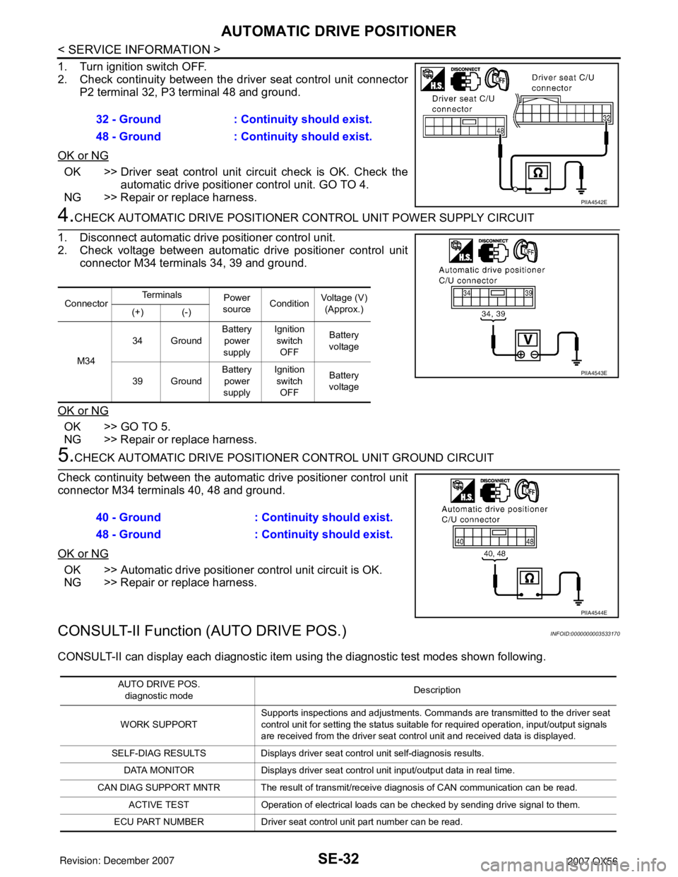
1. Turn ignition switch OFF.
2. Check continuity between the driver seat control unit connector
P2 terminal 32, P3 terminal 48 and ground.
OK or NG
OK >> Driver seat control unit circuit check is OK. Check the
automatic drive positioner control unit. GO TO 4.
NG >> Repair or replace harness.
4.CHECK AUTOMATIC DRIVE POSITIONER CONTROL UNIT POWER SUPPLY CIRCUIT
1. Disconnect automatic drive positioner control unit.
2. Check voltage between automatic drive positioner control unit
connector M34 terminals 34, 39 and ground.
OK or NG
OK >> GO TO 5.
NG >> Repair or replace harness.
5.CHECK AUTOMATIC DRIVE POSITIONER CONTROL UNIT GROUND CIRCUIT
Check continuity between the automatic drive positioner control unit
connector M34 terminals 40, 48 and ground.
OK or NG
OK >> Automatic drive positioner control unit circuit is OK.
NG >> Repair or replace harness.
CONSULT-II Function (AUTO DRIVE POS.)INFOID:0000000003533170
CONSULT-II can display each diagnostic item using the diagnostic test modes shown following. 32 - Ground : Continuity should exist.
48 - Ground : Continuity should exist.
PIIA4542E
ConnectorTe r m i n a l s
Power
sourceConditionVoltage (V)
(Approx.)
(+) (-)
M3434 GroundBattery
power
supplyIgnition
switch
OFFBattery
voltage
39 GroundBattery
power
supplyIgnition
switch
OFFBattery
voltage
PIIA4543E
40 - Ground : Continuity should exist.
48 - Ground : Continuity should exist.
PIIA4544E
AUTO DRIVE POS.
diagnostic modeDescription
WORK SUPPORTSupports inspections and adjustments. Commands are transmitted to the driver seat
control unit for setting the status suitable for required operation, input/output signals
are received from the driver seat control unit and received data is displayed.
SELF-DIAG RESULTS Displays driver seat control unit self-diagnosis results.
DATA MONITOR Displays driver seat control unit input/output data in real time.
CAN DIAG SUPPORT MNTR The result of transmit/receive diagnosis of CAN communication can be read.
ACTIVE TEST Operation of electrical loads can be checked by sending drive signal to them.
ECU PART NUMBER Driver seat control unit part number can be read.
Page 2710 of 3061
SE-38
< SERVICE INFORMATION >
AUTOMATIC DRIVE POSITIONER
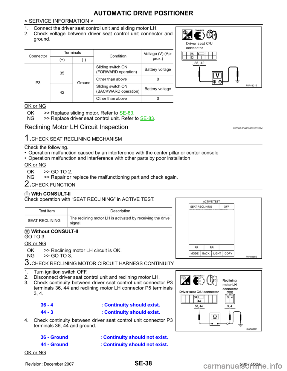
1. Connect the driver seat control unit and sliding motor LH.
2. Check voltage between driver seat control unit connector and
ground.
OK or NG
OK >> Replace sliding motor. Refer to SE-83.
NG >> Replace driver seat control unit. Refer to SE-83
.
Reclining Motor LH Circuit InspectionINFOID:0000000003533174
1.CHECK SEAT RECLINING MECHANISM
Check the following.
• Operation malfunction caused by an interference with the center pillar or center console
• Operation malfunction and interference with other parts by poor installation
OK or NG
OK >> GO TO 2.
NG >> Repair or replace the malfunctioning part and check again.
2.CHECK FUNCTION
With CONSULT-II
Check operation with “SEAT RECLINING” in ACTIVE TEST.
Without CONSULT-II
GO TO 3.
OK or NG
OK >> Reclining motor LH circuit is OK.
NG >> GO TO 3.
3.CHECK RECLINING MOTOR CIRCUIT HARNESS CONTINUITY
1. Turn ignition switch OFF.
2. Disconnect driver seat control unit and reclining motor LH.
3. Check continuity between driver seat control unit connector P3
terminals 36, 44 and reclining motor LH connector P5 terminals
3, 4.
4. Check continuity between driver seat control unit connector P3
terminals 36, 44 and ground.
OK or NG
ConnectorTe r m i n a l s
ConditionVoltage (V) (Ap-
prox.)
(+) (-)
P335
GroundSliding switch ON
(FORWARD operation)Battery voltage
Other than above 0
42Sliding switch ON
(BACKWARD operation)Battery voltage
Other than above 0
PIIA4801E
Test item Description
SEAT RECLININGThe reclining motor LH is activated by receiving the drive
signal.
PIIA0268E
36 - 4 : Continuity should exist.
44 - 3 : Continuity should exist.
36 - Ground : Continuity should not exist.
44 - Ground : Continuity should not exist.
LIIA0697E
Page 2711 of 3061
AUTOMATIC DRIVE POSITIONER
SE-39
< SERVICE INFORMATION >
C
D
E
F
G
H
J
K
L
MA
B
SE
N
O
P
OK >> GO TO 4.
NG >> Repair or replace harness.
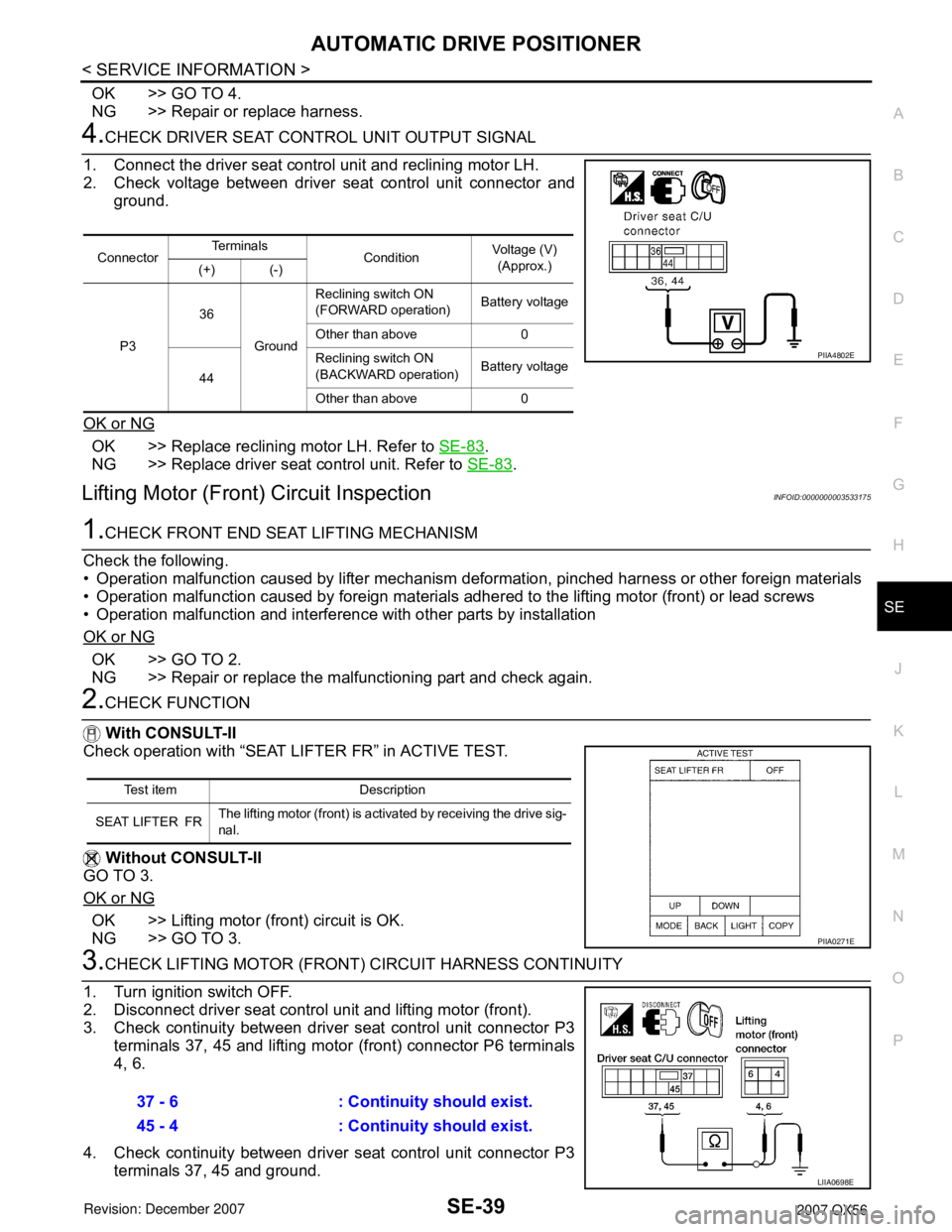
4.CHECK DRIVER SEAT CONTROL UNIT OUTPUT SIGNAL
1. Connect the driver seat control unit and reclining motor LH.
2. Check voltage between driver seat control unit connector and
ground.
OK or NG
OK >> Replace reclining motor LH. Refer to SE-83.
NG >> Replace driver seat control unit. Refer to SE-83
.
Lifting Motor (Front) Circuit InspectionINFOID:0000000003533175
1.CHECK FRONT END SEAT LIFTING MECHANISM
Check the following.
• Operation malfunction caused by lifter mechanism deformation, pinched harness or other foreign materials
• Operation malfunction caused by foreign materials adhered to the lifting motor (front) or lead screws
• Operation malfunction and interference with other parts by installation
OK or NG
OK >> GO TO 2.
NG >> Repair or replace the malfunctioning part and check again.
2.CHECK FUNCTION
With CONSULT-II
Check operation with “SEAT LIFTER FR” in ACTIVE TEST.
Without CONSULT-II
GO TO 3.
OK or NG
OK >> Lifting motor (front) circuit is OK.
NG >> GO TO 3.
3.CHECK LIFTING MOTOR (FRONT) CIRCUIT HARNESS CONTINUITY
1. Turn ignition switch OFF.
2. Disconnect driver seat control unit and lifting motor (front).
3. Check continuity between driver seat control unit connector P3
terminals 37, 45 and lifting motor (front) connector P6 terminals
4, 6.
4. Check continuity between driver seat control unit connector P3
terminals 37, 45 and ground.
ConnectorTe r m i n a l s
ConditionVoltage (V)
(Approx.)
(+) (-)
P336
GroundReclining switch ON
(FORWARD operation)Battery voltage
Other than above 0
44Reclining switch ON
(BACKWARD operation)Battery voltage
Other than above 0
PIIA4802E
Test item Description
SEAT LIFTER FRThe lifting motor (front) is activated by receiving the drive sig-
nal.
PIIA0271E
37 - 6 : Continuity should exist.
45 - 4 : Continuity should exist.
LIIA0698E