Page 1882 of 3061
EM-112
< SERVICE INFORMATION >
SERVICE DATA AND SPECIFICATIONS (SDS)
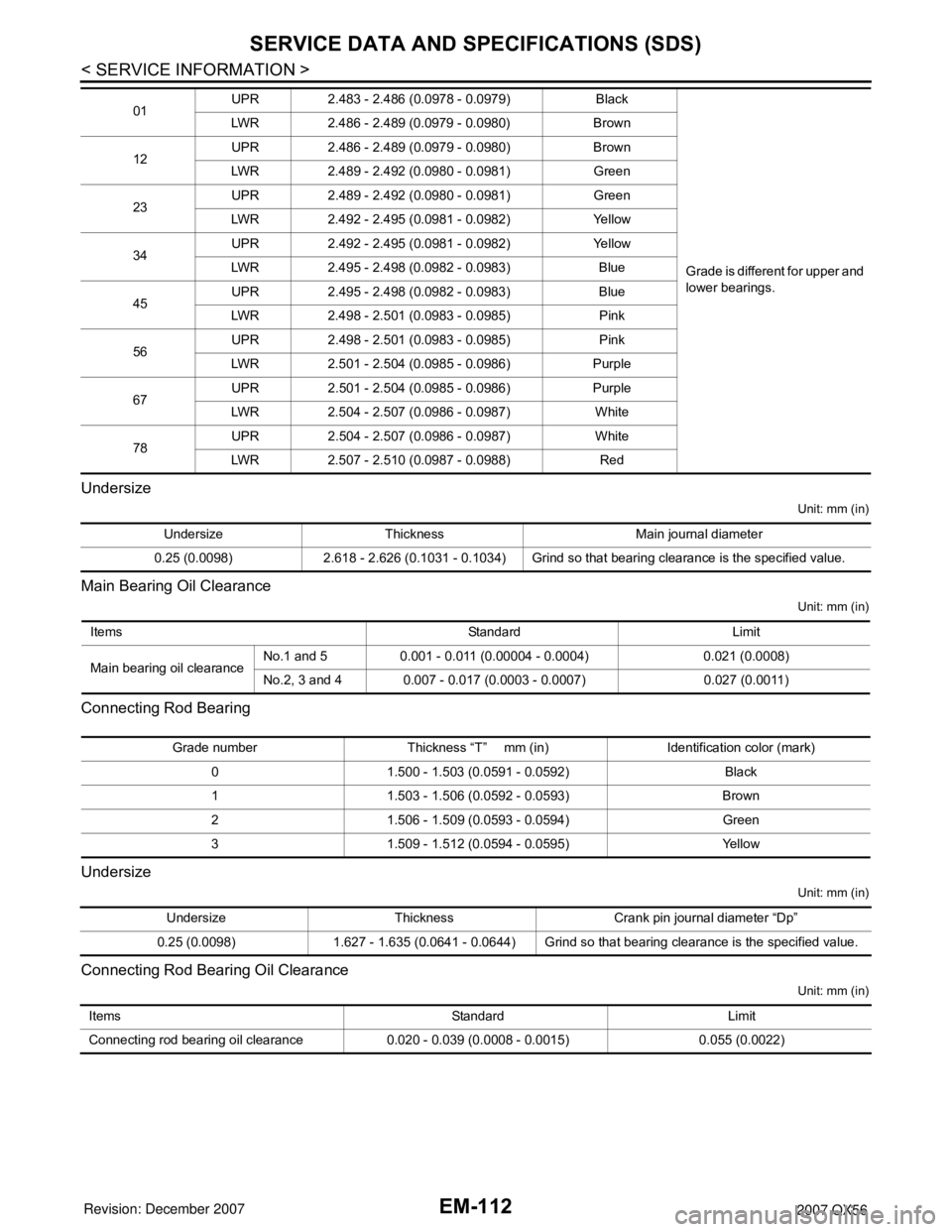
Undersize
Unit: mm (in)
Main Bearing Oil Clearance
Unit: mm (in)
Connecting Rod Bearing
Undersize
Unit: mm (in)
Connecting Rod Bearing Oil Clearance
Unit: mm (in)
01UPR 2.483 - 2.486 (0.0978 - 0.0979) Black
Grade is different for upper and
lower bearings. LWR 2.486 - 2.489 (0.0979 - 0.0980) Brown
12UPR 2.486 - 2.489 (0.0979 - 0.0980) Brown
LWR 2.489 - 2.492 (0.0980 - 0.0981) Green
23UPR 2.489 - 2.492 (0.0980 - 0.0981) Green
LWR 2.492 - 2.495 (0.0981 - 0.0982) Yellow
34UPR 2.492 - 2.495 (0.0981 - 0.0982) Yellow
LWR 2.495 - 2.498 (0.0982 - 0.0983) Blue
45UPR 2.495 - 2.498 (0.0982 - 0.0983) Blue
LWR 2.498 - 2.501 (0.0983 - 0.0985) Pink
56UPR 2.498 - 2.501 (0.0983 - 0.0985) Pink
LWR 2.501 - 2.504 (0.0985 - 0.0986) Purple
67UPR 2.501 - 2.504 (0.0985 - 0.0986) Purple
LWR 2.504 - 2.507 (0.0986 - 0.0987) White
78UPR 2.504 - 2.507 (0.0986 - 0.0987) White
LWR 2.507 - 2.510 (0.0987 - 0.0988) Red
Undersize Thickness Main journal diameter
0.25 (0.0098) 2.618 - 2.626 (0.1031 - 0.1034) Grind so that bearing clearance is the specified value.
Items Standard Limit
Main bearing oil clearanceNo.1 and 5 0.001 - 0.011 (0.00004 - 0.0004) 0.021 (0.0008)
No.2, 3 and 4 0.007 - 0.017 (0.0003 - 0.0007) 0.027 (0.0011)
Grade number Thickness “T” mm (in) Identification color (mark)
0 1.500 - 1.503 (0.0591 - 0.0592) Black
1 1.503 - 1.506 (0.0592 - 0.0593) Brown
2 1.506 - 1.509 (0.0593 - 0.0594) Green
3 1.509 - 1.512 (0.0594 - 0.0595) Yellow
Undersize Thickness Crank pin journal diameter “Dp”
0.25 (0.0098) 1.627 - 1.635 (0.0641 - 0.0644) Grind so that bearing clearance is the specified value.
Items Standard Limit
Connecting rod bearing oil clearance 0.020 - 0.039 (0.0008 - 0.0015) 0.055 (0.0022)
Page 1893 of 3061
DRIVE SHAFT
FAX-7
< SERVICE INFORMATION >
C
E
F
G
H
I
J
K
L
MA
B
FA X
N
O
P
DRIVE SHAFT
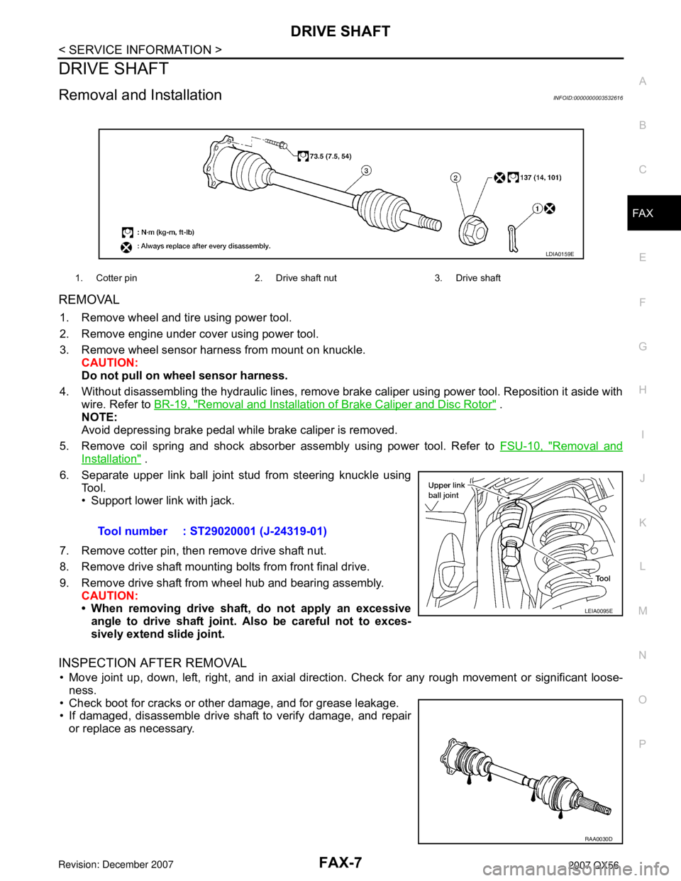
Removal and InstallationINFOID:0000000003532616
REMOVAL
1. Remove wheel and tire using power tool.
2. Remove engine under cover using power tool.
3. Remove wheel sensor harness from mount on knuckle.
CAUTION:
Do not pull on wheel sensor harness.
4. Without disassembling the hydraulic lines, remove brake caliper using power tool. Reposition it aside with
wire. Refer to BR-19, "
Removal and Installation of Brake Caliper and Disc Rotor" .
NOTE:
Avoid depressing brake pedal while brake caliper is removed.
5. Remove coil spring and shock absorber assembly using power tool. Refer to FSU-10, "
Removal and
Installation" .
6. Separate upper link ball joint stud from steering knuckle using
Tool.
• Support lower link with jack.
7. Remove cotter pin, then remove drive shaft nut.
8. Remove drive shaft mounting bolts from front final drive.
9. Remove drive shaft from wheel hub and bearing assembly.
CAUTION:
• When removing drive shaft, do not apply an excessive
angle to drive shaft joint. Also be careful not to exces-
sively extend slide joint.
INSPECTION AFTER REMOVAL
• Move joint up, down, left, right, and in axial direction. Check for any rough movement or significant loose-
ness.
• Check boot for cracks or other damage, and for grease leakage.
• If damaged, disassemble drive shaft to verify damage, and repair
or replace as necessary.
1. Cotter pin 2. Drive shaft nut 3. Drive shaft
LDIA0159E
Tool number : ST29020001 (J-24319-01)
LEIA0095E
RAA0030D
Page 1900 of 3061
FFD-1
DRIVELINE/AXLE
C
E
F
G
H
I
J
K
L
M
SECTION FFD
A
B
FFD
N
O
P
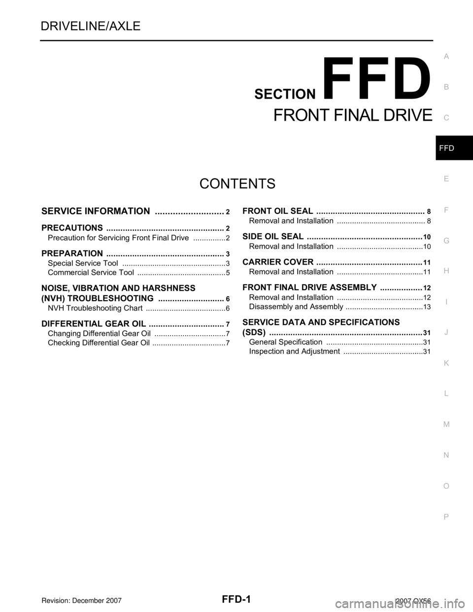
CONTENTS
FRONT FINAL DRIVE
SERVICE INFORMATION ............................2
PRECAUTIONS ...................................................2
Precaution for Servicing Front Final Drive ................2
PREPARATION ...................................................3
Special Service Tool .................................................3
Commercial Service Tool ..........................................5
NOISE, VIBRATION AND HARSHNESS
(NVH) TROUBLESHOOTING .............................
6
NVH Troubleshooting Chart ......................................6
DIFFERENTIAL GEAR OIL .................................7
Changing Differential Gear Oil ..................................7
Checking Differential Gear Oil ...................................7
FRONT OIL SEAL ..............................................8
Removal and Installation ..........................................8
SIDE OIL SEAL .................................................10
Removal and Installation .........................................10
CARRIER COVER .............................................11
Removal and Installation .........................................11
FRONT FINAL DRIVE ASSEMBLY ..................12
Removal and Installation .........................................12
Disassembly and Assembly .....................................13
SERVICE DATA AND SPECIFICATIONS
(SDS) .................................................................
31
General Specification ..............................................31
Inspection and Adjustment ......................................31
Page 1901 of 3061
FFD-2
< SERVICE INFORMATION >
PRECAUTIONS
SERVICE INFORMATION
PRECAUTIONS
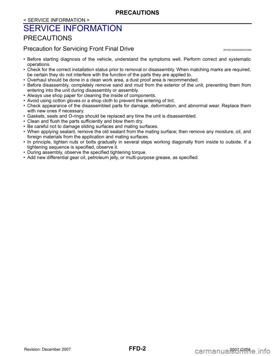
Precaution for Servicing Front Final DriveINFOID:0000000003532584
• Before starting diagnosis of the vehicle, understand the symptoms well. Perform correct and systematic
operations.
• Check for the correct installation status prior to removal or disassembly. When matching marks are required,
be certain they do not interfere with the function of the parts they are applied to.
• Overhaul should be done in a clean work area, a dust proof area is recommended.
• Before disassembly, completely remove sand and mud from the exterior of the unit, preventing them from
entering into the unit during disassembly or assembly.
• Always use shop paper for cleaning the inside of components.
• Avoid using cotton gloves or a shop cloth to prevent the entering of lint.
• Check appearance of the disassembled parts for damage, deformation, and abnormal wear. Replace them
with new ones if necessary.
• Gaskets, seals and O-rings should be replaced any time the unit is disassembled.
• Clean and flush the parts sufficiently and blow them dry.
• Be careful not to damage sliding surfaces and mating surfaces.
• When applying sealant, remove the old sealant from the mating surface; then remove any moisture, oil, and
foreign materials from the application and mating surfaces.
• In principle, tighten nuts or bolts gradually in several steps working diagonally from inside to outside. If a
tightening sequence is specified, observe it.
• During assembly, observe the specified tightening torque.
• Add new differential gear oil, petroleum jelly, or multi-purpose grease, as specified.
Page 1902 of 3061
PREPARATION
FFD-3
< SERVICE INFORMATION >
C
E
F
G
H
I
J
K
L
MA
B
FFD
N
O
P
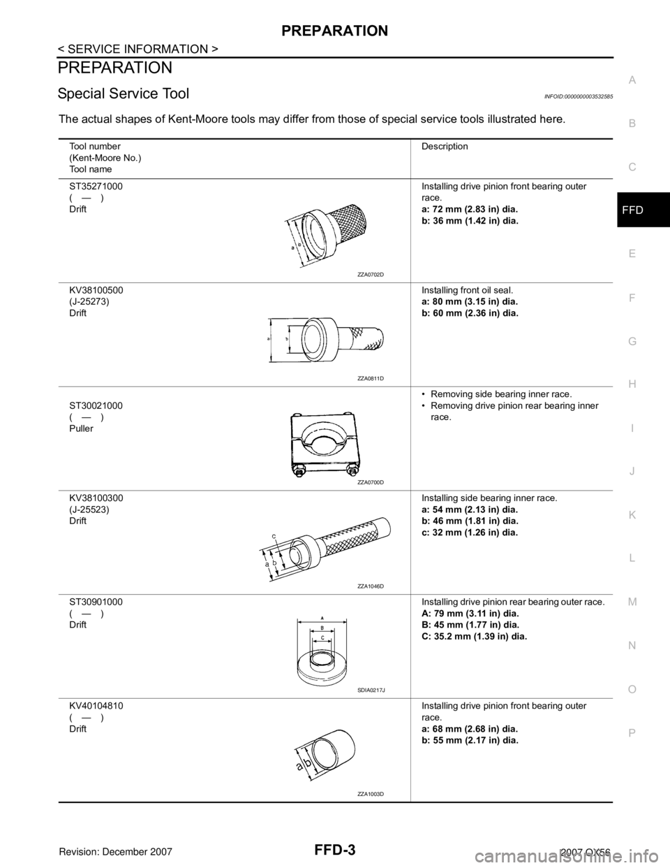
PREPARATION
Special Service ToolINFOID:0000000003532585
The actual shapes of Kent-Moore tools may differ from those of special service tools illustrated here.
Tool number
(Kent-Moore No.)
Tool nameDescription
ST35271000
(—)
DriftInstalling drive pinion front bearing outer
race.
a: 72 mm (2.83 in) dia.
b: 36 mm (1.42 in) dia.
KV38100500
(J-25273)
DriftInstalling front oil seal.
a: 80 mm (3.15 in) dia.
b: 60 mm (2.36 in) dia.
ST30021000
(—)
Puller• Removing side bearing inner race.
• Removing drive pinion rear bearing inner
race.
KV38100300
(J-25523)
DriftInstalling side bearing inner race.
a: 54 mm (2.13 in) dia.
b: 46 mm (1.81 in) dia.
c: 32 mm (1.26 in) dia.
ST30901000
(—)
DriftInstalling drive pinion rear bearing outer race.
A: 79 mm (3.11 in) dia.
B: 45 mm (1.77 in) dia.
C: 35.2 mm (1.39 in) dia.
KV40104810
(—)
DriftInstalling drive pinion front bearing outer
race.
a: 68 mm (2.68 in) dia.
b: 55 mm (2.17 in) dia.
ZZA0702D
ZZA0811D
ZZA0700D
ZZA1046D
SDIA0217J
ZZA1003D
Page 1903 of 3061
FFD-4
< SERVICE INFORMATION >
PREPARATION
KV38102200
(—)
DriftInstalling front oil seal.
a: 90 mm (3.54 in) dia.
b: 55.3 mm (2.18 in) dia.
ST33081000
(—)
AdapterRemoving and installing side bearing inner
race.
a: 43 mm (1.69 in) dia.
b: 33.5 mm (1.32 in) dia.
KV38108300
(J-44195)
Companion flange wrenchRemoving and installing drive pinion nut.
ST3127S000
(J-25765-A)
Preload gauge
1. GG91030000
(J-25765)
Torque wrench
2. HT62940000
( — )
Socket adapter (1/2″)
3. HT62900000
( — )
Socket adapter (3/8″)Inspecting drive pinion bearing preload and
total preload
—
(C-4040)
InstallerInstalling drive pinion rear bearing inner race.
KV40105230
(—)
DriftInstalling drive pinion rear bearing outer race.
a: 92 mm (3.62 in) dia.
b: 85.5 mm (3.37 in) dia. Tool number
(Kent-Moore No.)
Tool nameDescription
NT660
ZZA1000D
NT771
NT124
SDIA2607E
ZZA0898D
Page 1904 of 3061
PREPARATION
FFD-5
< SERVICE INFORMATION >
C
E
F
G
H
I
J
K
L
MA
B
FFD
N
O
P
Commercial Service ToolINFOID:0000000003532586
—
(C-4171)
Handle• Removing drive pinion front bearing outer
race
• Removing drive pinion rear bearing outer
race
—
(D-103)
RemoverRemoving drive pinion front bearing outer
race
—
(C-4307)
RemoverRemoving drive pinion rear bearing outer
race Tool number
(Kent-Moore No.)
Tool nameDescription
LDIA0134E
LDIA0135E
LDIA0135E
(Kent-Moore No.)
Tool nameDescription
(SP8P)
Slide hammer• Removing front oil seal
• Removing side oil seal
Power toolLoosening bolts and nuts
LDIA0133E
PBIC0190E
Page 1905 of 3061
FFD-6
< SERVICE INFORMATION >
NOISE, VIBRATION AND HARSHNESS (NVH) TROUBLESHOOTING
NOISE, VIBRATION AND HARSHNESS (NVH) TROUBLESHOOTING
NVH Troubleshooting ChartINFOID:0000000003532587
Use the chart below to help you find the cause of the symptom. If necessary, repair or replace these parts.
×: ApplicableReference page
FFD-13FFD-13FFD-13FFD-13FFD-13FFD-7
PR-3, "
NVH Troubleshooting Chart
"
FAX-4, "
NVH Troubleshooting Chart
"
FSU-4, "
NVH Troubleshooting Chart
"
WT-4, "
NVH Troubleshooting Chart
"
WT-4, "
NVH Troubleshooting Chart
"
FAX-4, "
NVH Troubleshooting Chart
"
BR-4, "
NVH Troubleshooting Chart
"
PS-5, "
NVH Troubleshooting Chart
"
Possible cause and SUSPECTED PARTS
Gear tooth rough
Gear contact improper
Tooth surfaces worn
Incorrect backlash
Companion flange excessive runout
Gear oil improper
PROPELLER SHAFT
FRONT AXLE
FRONT SUSPENSION
TIRES
ROAD WHEEL
DRIVE SHAFT
BRAKES
STEERING
Symptom Noise××××××××××××××