2007 INFINITI QX56 high beam
[x] Cancel search: high beamPage 2222 of 3061
HEADLAMP (FOR USA)
LT-15
< SERVICE INFORMATION >
C
D
E
F
G
H
I
J
L
MA
B
LT
N
O
P
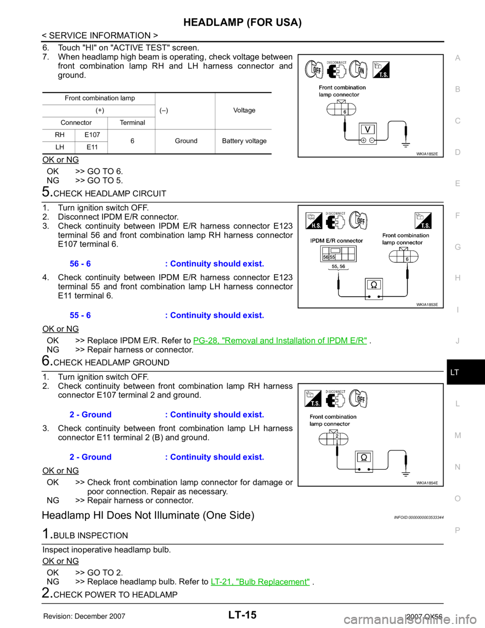
6. Touch "HI" on "ACTIVE TEST" screen.
7. When headlamp high beam is operating, check voltage between
front combination lamp RH and LH harness connector and
ground.
OK or NG
OK >> GO TO 6.
NG >> GO TO 5.
5.CHECK HEADLAMP CIRCUIT
1. Turn ignition switch OFF.
2. Disconnect IPDM E/R connector.
3. Check continuity between IPDM E/R harness connector E123
terminal 56 and front combination lamp RH harness connector
E107 terminal 6.
4. Check continuity between IPDM E/R harness connector E123
terminal 55 and front combination lamp LH harness connector
E11 terminal 6.
OK or NG
OK >> Replace IPDM E/R. Refer to PG-28, "Removal and Installation of IPDM E/R" .
NG >> Repair harness or connector.
6.CHECK HEADLAMP GROUND
1. Turn ignition switch OFF.
2. Check continuity between front combination lamp RH harness
connector E107 terminal 2 and ground.
3. Check continuity between front combination lamp LH harness
connector E11 terminal 2 (B) and ground.
OK or NG
OK >> Check front combination lamp connector for damage or
poor connection. Repair as necessary.
NG >> Repair harness or connector.
Headlamp HI Does Not Illuminate (One Side)INFOID:0000000003533344
1.BULB INSPECTION
Inspect inoperative headlamp bulb.
OK or NG
OK >> GO TO 2.
NG >> Replace headlamp bulb. Refer to LT-21, "
Bulb Replacement" .
2.CHECK POWER TO HEADLAMP
Front combination lamp
(–) Voltage (+)
Connector Terminal
RH E107
6 Ground Battery voltage
LH E11
WKIA1852E
56 - 6 : Continuity should exist.
55 - 6 : Continuity should exist.
WKIA1853E
2 - Ground : Continuity should exist.
2 - Ground : Continuity should exist.
WKIA1854E
Page 2223 of 3061
LT-16
< SERVICE INFORMATION >
HEADLAMP (FOR USA)
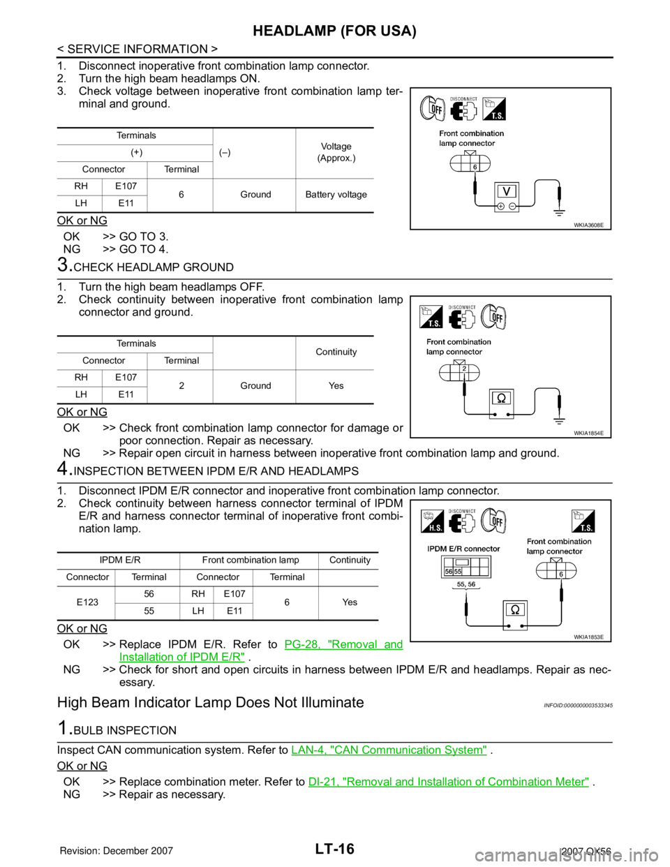
1. Disconnect inoperative front combination lamp connector.
2. Turn the high beam headlamps ON.
3. Check voltage between inoperative front combination lamp ter-
minal and ground.
OK or NG
OK >> GO TO 3.
NG >> GO TO 4.
3.CHECK HEADLAMP GROUND
1. Turn the high beam headlamps OFF.
2. Check continuity between inoperative front combination lamp
connector and ground.
OK or NG
OK >> Check front combination lamp connector for damage or
poor connection. Repair as necessary.
NG >> Repair open circuit in harness between inoperative front combination lamp and ground.
4.INSPECTION BETWEEN IPDM E/R AND HEADLAMPS
1. Disconnect IPDM E/R connector and inoperative front combination lamp connector.
2. Check continuity between harness connector terminal of IPDM
E/R and harness connector terminal of inoperative front combi-
nation lamp.
OK or NG
OK >> Replace IPDM E/R. Refer to PG-28, "Removal and
Installation of IPDM E/R" .
NG >> Check for short and open circuits in harness between IPDM E/R and headlamps. Repair as nec-
essary.
High Beam Indicator Lamp Does Not IlluminateINFOID:0000000003533345
1.BULB INSPECTION
Inspect CAN communication system. Refer to LAN-4, "
CAN Communication System" .
OK or NG
OK >> Replace combination meter. Refer to DI-21, "Removal and Installation of Combination Meter" .
NG >> Repair as necessary.
Te r m i n a l s
(–)Vo l ta g e
(Approx.) (+)
Connector Terminal
RH E107
6 Ground Battery voltage
LH E11
WKIA3608E
Te r m i n a l s
Continuity
Connector Terminal
RH E107
2 Ground Yes
LH E11
WKIA1854E
IPDM E/R Front combination lamp Continuity
Connector Terminal Connector Terminal
E12356 RH E107
6Yes
55 LH E11
WKIA1853E
Page 2228 of 3061
HEADLAMP (FOR USA)
LT-21
< SERVICE INFORMATION >
C
D
E
F
G
H
I
J
L
MA
B
LT
N
O
P
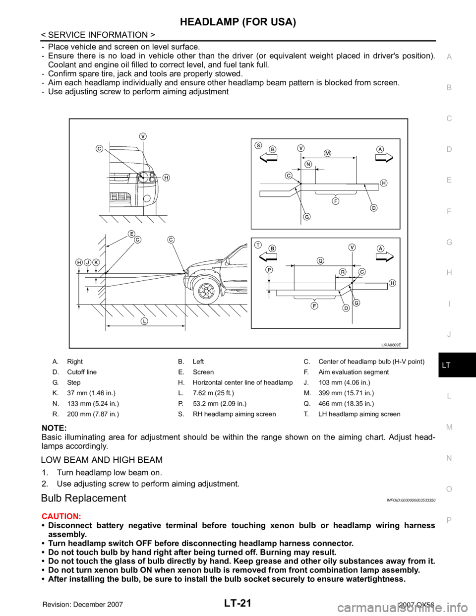
- Place vehicle and screen on level surface.
- Ensure there is no load in vehicle other than the driver (or equivalent weight placed in driver's position).
Coolant and engine oil filled to correct level, and fuel tank full.
- Confirm spare tire, jack and tools are properly stowed.
- Aim each headlamp individually and ensure other headlamp beam pattern is blocked from screen.
- Use adjusting screw to perform aiming adjustment
NOTE:
Basic illuminating area for adjustment should be within the range shown on the aiming chart. Adjust head-
lamps accordingly.
LOW BEAM AND HIGH BEAM
1. Turn headlamp low beam on.
2. Use adjusting screw to perform aiming adjustment.
Bulb ReplacementINFOID:0000000003533350
CAUTION:
• Disconnect battery negative terminal before touching xenon bulb or headlamp wiring harness
assembly.
• Turn headlamp switch OFF before disconnecting headlamp harness connector.
• Do not touch bulb by hand right after being turned off. Burning may result.
• Do not touch the glass of bulb directly by hand. Keep grease and other oily substances away from it.
• Do not turn xenon bulb ON when xenon bulb is removed from front combination lamp assembly.
• After installing the bulb, be sure to install the bulb socket securely to ensure watertightness.
A. Right B. Left C. Center of headlamp bulb (H-V point)
D. Cutoff line E. Screen F. Aim evaluation segment
G. Step H. Horizontal center line of headlamp J. 103 mm (4.06 in.)
K. 37 mm (1.46 in.) L. 7.62 m (25 ft.) M. 399 mm (15.71 in.)
N. 133 mm (5.24 in.) P. 53.2 mm (2.09 in.) Q. 466 mm (18.35 in.)
R. 200 mm (7.87 in.) S. RH headlamp aiming screen T. LH headlamp aiming screen
LKIA0809E
Page 2229 of 3061

LT-22
< SERVICE INFORMATION >
HEADLAMP (FOR USA)
• Do not leave bulb out of front combination lamp assembly for a long time because dust, moisture,
smoke, etc. may affect the performance of the lamp. When replacing bulb, be sure to replace it with a
new one.
HEADLAMP (OUTER SIDE), FOR LOW BEAM
Removal
1. Position fender protector aside.
2. Turn headlamp switch OFF.
3. Disconnect battery negative terminal.
4. Remove ballast.
5. Disconnect headlamp electrical connector.
6. Release bulb retaining spring and pull bulb straight out.
Installation
Installation is in the reverse order of removal.
HEADLAMP (INNER SIDE), FOR HIGH BEAM
Removal
1. Turn headlamp switch OFF.
2. Disconnect headlamp electrical connector.
3. Turn the bulb counterclockwise to remove it.
Installation
Installation is in the reverse order of removal.
FRONT PARKING LAMP (INNER OR OUTER)
Removal
1. Turn the bulb socket counterclockwise to unlock it.
2. Pull the bulb to remove it from the socket.
Installation
Installation is in the reverse order of removal.
SIDE MARKER LAMP (FRONT)
Removal
1. Position fender protector aside.
2. Turn the side marker lamp (front) bulb socket counterclockwise and remove side marker lamp (front) bulb
socket.
3. Pull to remove side marker lamp (front) from the side marker lamp (front) bulb socket.
Installation
Installation is in the reverse order of removal.
Removal and InstallationINFOID:0000000003533351
FRONT COMBINATION LAMP ASSEMBLY
CAUTION:
• Disconnect battery negative terminal before touching xenon bulb or headlamp wiring harness
assembly.
• Turn headlamp switch OFF before disconnecting headlamp harness connector.
• Do not touch bulb by hand right after being turned off. Burning may result.
• Do not touch the glass of bulb directly by hand. Keep grease and other oily substances away from it.
• Do not turn xenon bulb ON when xenon bulb is removed from front combination lamp assembly.
• After installing the bulb, be sure to install the bulb socket securely to ensure watertightness.
• Do not leave bulb out of front combination lamp assembly for a long time because dust, moisture,
smoke, etc. may affect the performance of the lamp. When replacing bulb, be sure to replace it with a
new one.
Removal
Page 2230 of 3061
HEADLAMP (FOR USA)
LT-23
< SERVICE INFORMATION >
C
D
E
F
G
H
I
J
L
MA
B
LT
N
O
P
1. Disconnect battery negative terminal.
2. Disconnect front combination lamp assembly.
3. Remove front fascia. Refer to EI-12
.
4. Remove front combination lamp assembly bolts.
5. Remove front combination lamp assembly.
Installation
Installation is in the reverse order of removal.
Disassembly and AssemblyINFOID:0000000003533352
FRONT COMBINATION LAMP ASSEMBLY
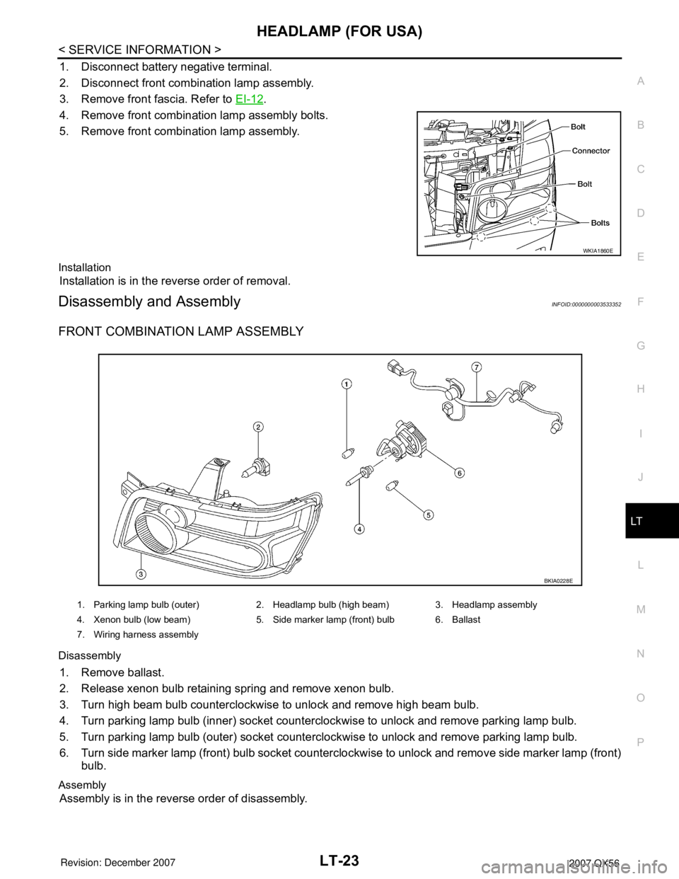
Disassembly
1. Remove ballast.
2. Release xenon bulb retaining spring and remove xenon bulb.
3. Turn high beam bulb counterclockwise to unlock and remove high beam bulb.
4. Turn parking lamp bulb (inner) socket counterclockwise to unlock and remove parking lamp bulb.
5. Turn parking lamp bulb (outer) socket counterclockwise to unlock and remove parking lamp bulb.
6. Turn side marker lamp (front) bulb socket counterclockwise to unlock and remove side marker lamp (front)
bulb.
Assembly
Assembly is in the reverse order of disassembly.
WKIA1860E
1. Parking lamp bulb (outer) 2. Headlamp bulb (high beam) 3. Headlamp assembly
4. Xenon bulb (low beam) 5. Side marker lamp (front) bulb 6. Ballast
7. Wiring harness assembly
BKIA0228E
Page 2232 of 3061
HEADLAMP (FOR CANADA) - DAYTIME LIGHT SYSTEM -
LT-25
< SERVICE INFORMATION >
C
D
E
F
G
H
I
J
L
MA
B
LT
N
O
P
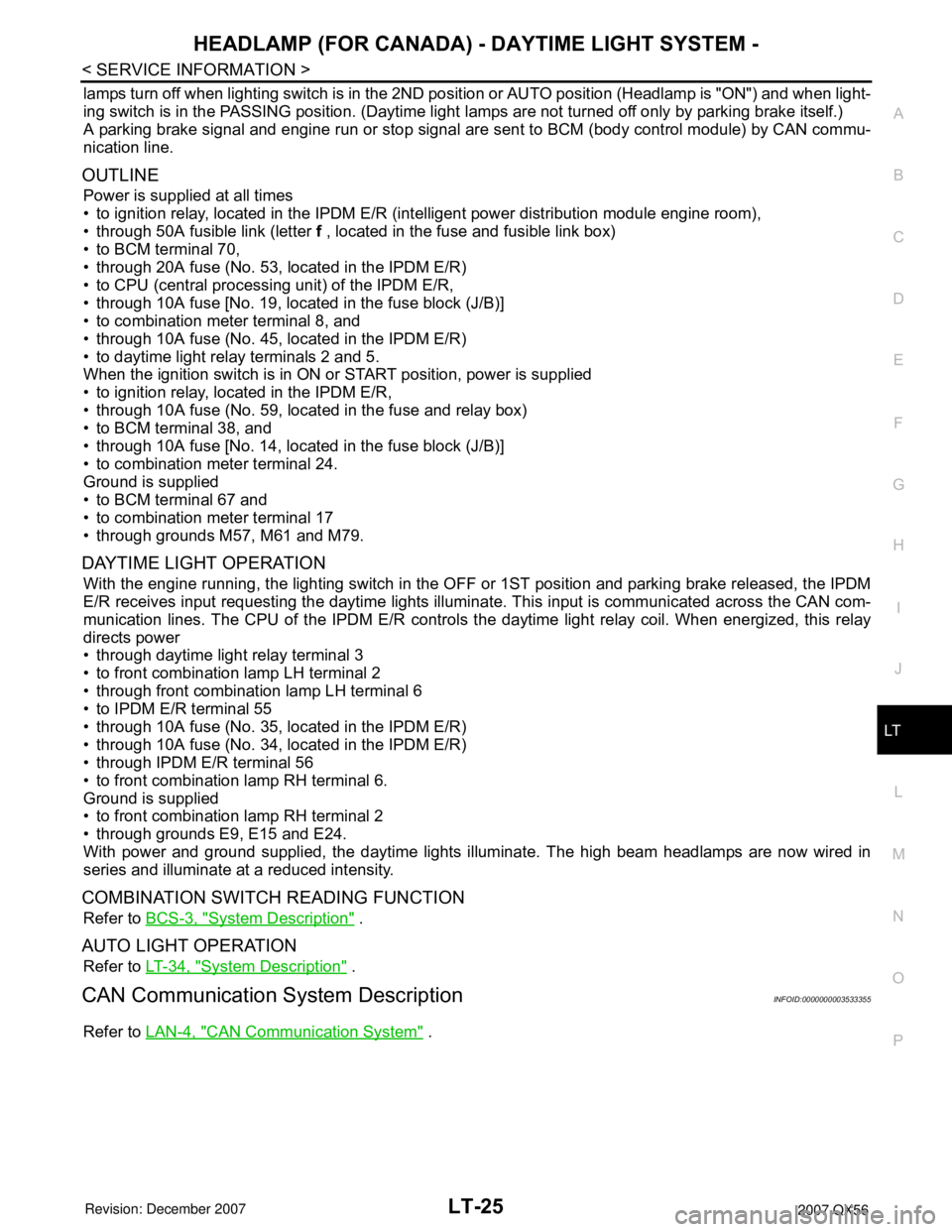
lamps turn off when lighting switch is in the 2ND position or AUTO position (Headlamp is "ON") and when light-
ing switch is in the PASSING position. (Daytime light lamps are not turned off only by parking brake itself.)
A parking brake signal and engine run or stop signal are sent to BCM (body control module) by CAN commu-
nication line.
OUTLINE
Power is supplied at all times
• to ignition relay, located in the IPDM E/R (intelligent power distribution module engine room),
• through 50A fusible link (letter f , located in the fuse and fusible link box)
• to BCM terminal 70,
• through 20A fuse (No. 53, located in the IPDM E/R)
• to CPU (central processing unit) of the IPDM E/R,
• through 10A fuse [No. 19, located in the fuse block (J/B)]
• to combination meter terminal 8, and
• through 10A fuse (No. 45, located in the IPDM E/R)
• to daytime light relay terminals 2 and 5.
When the ignition switch is in ON or START position, power is supplied
• to ignition relay, located in the IPDM E/R,
• through 10A fuse (No. 59, located in the fuse and relay box)
• to BCM terminal 38, and
• through 10A fuse [No. 14, located in the fuse block (J/B)]
• to combination meter terminal 24.
Ground is supplied
• to BCM terminal 67 and
• to combination meter terminal 17
• through grounds M57, M61 and M79.
DAYTIME LIGHT OPERATION
With the engine running, the lighting switch in the OFF or 1ST position and parking brake released, the IPDM
E/R receives input requesting the daytime lights illuminate. This input is communicated across the CAN com-
munication lines. The CPU of the IPDM E/R controls the daytime light relay coil. When energized, this relay
directs power
• through daytime light relay terminal 3
• to front combination lamp LH terminal 2
• through front combination lamp LH terminal 6
• to IPDM E/R terminal 55
• through 10A fuse (No. 35, located in the IPDM E/R)
• through 10A fuse (No. 34, located in the IPDM E/R)
• through IPDM E/R terminal 56
• to front combination lamp RH terminal 6.
Ground is supplied
• to front combination lamp RH terminal 2
• through grounds E9, E15 and E24.
With power and ground supplied, the daytime lights illuminate. The high beam headlamps are now wired in
series and illuminate at a reduced intensity.
COMBINATION SWITCH READING FUNCTION
Refer to BCS-3, "System Description" .
AUTO LIGHT OPERATION
Refer to LT-34, "System Description" .
CAN Communication System DescriptionINFOID:0000000003533355
Refer to LAN-4, "CAN Communication System" .
Page 2247 of 3061

LT-40
< SERVICE INFORMATION >
AUTO LIGHT SYSTEM
How to Proceed with Trouble Diagnosis
INFOID:0000000003533376
1. Confirm the symptom or customer complaint.
2. Understand operation description and function description. Refer to LT-34, "
System Description" .
3. Carry out the Preliminary Check. Refer to LT-40, "
Preliminary Check" .
4. Check symptom and repair or replace the component. Refer to LT-42, "
Trouble Diagnosis Chart by Symp-
tom" .
5. Does the auto light system operate normally? If YES: GO TO 6. If NO: GO TO 4.
6. Inspection End.
Preliminary CheckINFOID:0000000003533377
SETTING CHANGE FUNCTIONS
• Sensitivity of auto light system can be adjusted using CONSULT-II. Refer to LT-40, "CONSULT-II Function
(BCM)" .
CHECK POWER SUPPLY AND GROUND CIRCUIT FOR BCM
Refer to BCS-15, "BCM Power Supply and Ground Circuit Inspection" .
CHECK POWER SUPPLY AND GROUND CIRCUIT FOR IPDM E/R
Refer to PG-26, "IPDM E/R Power/Ground Circuit Inspection" .
CONSULT-II Function (BCM)INFOID:0000000003533378
Refer to BCS-16, "CONSULT-II Function (BCM)".
CONSULT-II START PROCEDURE
Refer to GI-36, "CONSULT-II Start Procedure" .
WORK SUPPORT
Work Support Setting Item
• Delay timer setting can be selected and set from eight modes.
• Sensitivity of auto light can be selected and set from four modes.
DATA MONITOR
Display Item List
Work item Description
CUSTOM A/LIGHT SETTINGAuto light sensitivity can be changed in this mode. Sensitivity can be adjusted in four modes.
• MODE 1 (Normal-default)/ MODE 2 (Desensitized)/MODE 3 (Sensitive)/MODE4 (Insensitive)
ILL DELAY SETAuto light delay off timer period can be changed in this mode. Selects auto light delay off timer period
among eight modes.
• MODE 1 (45 sec.)/MODE 2 (OFF)/MODE 3 (30 sec.)/MODE 4 (60 sec.)/MODE 5 (90 sec.)/MODE
6 (120 sec.)/MODE 7 (150 sec.)/MODE 8 (180 sec.)
Monitor item Contents
IGN ON SW "ON/OFF" Displays "IGN position (ON)/OFF, ACC position (OFF)" judged from the ignition switch signal.
ACC ON SW "ON/OFF" Displays "ACC (ON)/OFF, Ignition OFF (OFF)" status judged from ignition switch signal.
HI BEAM SW "ON/OFF"Displays status (high beam switch: ON/Others: OFF) of high beam switch judged from lighting
switch signal.
HEAD LAMP SW 1 "ON/OFF"Displays status (headlamp switch 1: ON/Others: OFF) of headlamp switch 2 judged from light-
ing switch signal.
HEAD LAMP SW 2 "ON/OFF"Displays status (headlamp switch 2: ON/Others: OFF) of headlamp switch 2 judged from light-
ing switch signal.
LIGHT SW 1ST "ON/OFF"Displays status (lighting switch 1st position: ON/Others: OFF) of lighting switch judged from
lighting switch signal.
Page 2249 of 3061
LT-42
< SERVICE INFORMATION >
AUTO LIGHT SYSTEM
NOTE:
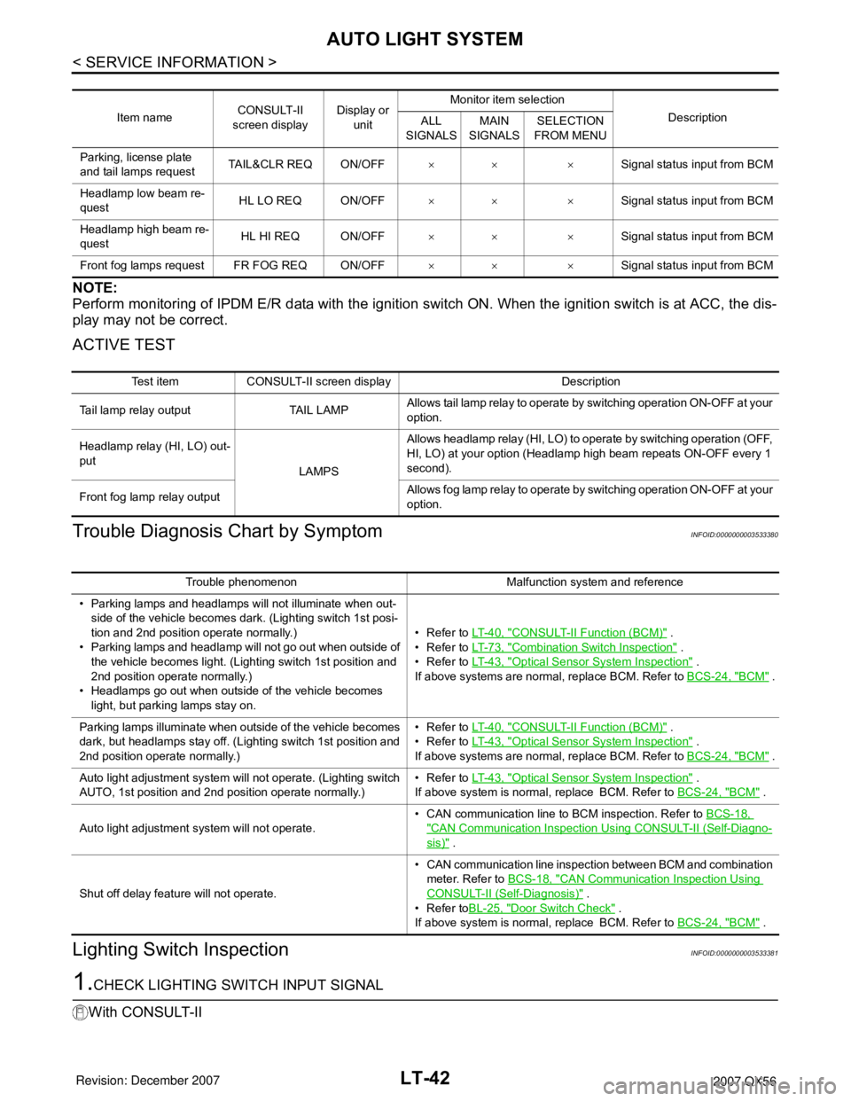
Perform monitoring of IPDM E/R data with the ignition switch ON. When the ignition switch is at ACC, the dis-
play may not be correct.
ACTIVE TEST
Trouble Diagnosis Chart by SymptomINFOID:0000000003533380
Lighting Switch InspectionINFOID:0000000003533381
1.CHECK LIGHTING SWITCH INPUT SIGNAL
With CONSULT-II
Item nameCONSULT-II
screen displayDisplay or
unitMonitor item selection
Description
ALL
SIGNALSMAIN
SIGNALSSELECTION
FROM MENU
Parking, license plate
and tail lamps requestTAIL&CLR REQ ON/OFF×× ×Signal status input from BCM
Headlamp low beam re-
questHL LO REQ ON/OFF×× ×Signal status input from BCM
Headlamp high beam re-
questHL HI REQ ON/OFF×× ×Signal status input from BCM
Front fog lamps request FR FOG REQ ON/OFF×× ×Signal status input from BCM
Test item CONSULT-II screen display Description
Tail lamp relay output TAIL LAMPAllows tail lamp relay to operate by switching operation ON-OFF at your
option.
Headlamp relay (HI, LO) out-
put
LAMPSAllows headlamp relay (HI, LO) to operate by switching operation (OFF,
HI, LO) at your option (Headlamp high beam repeats ON-OFF every 1
second).
Front fog lamp relay outputAllows fog lamp relay to operate by switching operation ON-OFF at your
option.
Trouble phenomenon Malfunction system and reference
• Parking lamps and headlamps will not illuminate when out-
side of the vehicle becomes dark. (Lighting switch 1st posi-
tion and 2nd position operate normally.)
• Parking lamps and headlamp will not go out when outside of
the vehicle becomes light. (Lighting switch 1st position and
2nd position operate normally.)
• Headlamps go out when outside of the vehicle becomes
light, but parking lamps stay on.•Refer to LT- 4 0 , "
CONSULT-II Function (BCM)" .
•Refer to LT- 7 3 , "
Combination Switch Inspection" .
•Refer to LT- 4 3 , "
Optical Sensor System Inspection" .
If above systems are normal, replace BCM. Refer to BCS-24, "
BCM" .
Parking lamps illuminate when outside of the vehicle becomes
dark, but headlamps stay off. (Lighting switch 1st position and
2nd position operate normally.)•Refer to LT- 4 0 , "
CONSULT-II Function (BCM)" .
•Refer to LT- 4 3 , "
Optical Sensor System Inspection" .
If above systems are normal, replace BCM. Refer to BCS-24, "
BCM" .
Auto light adjustment system will not operate. (Lighting switch
AUTO, 1st position and 2nd position operate normally.)•Refer to LT- 4 3 , "
Optical Sensor System Inspection" .
If above system is normal, replace BCM. Refer to BCS-24, "
BCM" .
Auto light adjustment system will not operate.• CAN communication line to BCM inspection. Refer to BCS-18,
"CAN Communication Inspection Using CONSULT-II (Self-Diagno-
sis)" .
Shut off delay feature will not operate.• CAN communication line inspection between BCM and combination
meter. Refer to BCS-18, "
CAN Communication Inspection Using
CONSULT-II (Self-Diagnosis)" .
•Refer toBL-25, "
Door Switch Check" .
If above system is normal, replace BCM. Refer to BCS-24, "
BCM" .