Page 837 of 3061

BL-126
< SERVICE INFORMATION >
IVIS (INFINITI VEHICLE IMMOBILIZER SYSTEM-NATS)
OK or NG
OK >> GO TO 3.
NG >> Check the following:
• 50A fusible link (letter f , located in fuse and fusible
link box)
• Harness for open or short between fuse and BCM
connector. Ref. Part No. C1
3.CHECK IGN SW. ON SIGNAL
1. Turn ignition switch ON.
2. Check voltage between BCM connector M18 terminal 38 and ground.
OK or NG
OK >> GO TO 4.
NG >> Check the following:
• 10A fuse [No. 59, located in the fuse and relay box]
• Harness for open or short between fuse and BCM
connector. Ref. part No. C2
4.CHECK GROUND CIRCUIT FOR BCM
1. Turn ignition switch OFF.
2. Check continuity between BCM connector M18 terminal 67 and ground.
OK or NG
OK >> GO TO 5.
NG >> Repair or replace harness. Ref. part No. C3
5.REPLACE BCM
1. Replace BCM. Ref. part No. A
2. Perform initialization with CONSULT-II.
For initialization, refer to “CONSULT-II Operation Manual NATS-IVIS/NVIS”.
Does the engine start?
YES >> BCM is malfunctioning.
NO >> ECM is malfunctioning.
• Replace ECM. Ref. part No. B
• Perform initialization or re-communicating function.
• For initialization, refer to “CONSULT-II Operation Manual NATS-IVIS/NVIS”.
• For re-communicating function, refer to BL-117, "
ECM Re-communicating Function".
Diagnosis Procedure 2INFOID:0000000003532996
Self-diagnostic results:
“DIFFERENCE OF KEY” displayed on CONSULT-II screen
1.CONFIRM SELF-DIAGNOSTIC RESULTS70 - Ground :Battery voltage
LIIA1279E
38 - Ground :Battery voltage
LIIA0527E
67 - Ground :Continuity should exist.
LIIA1040E
Page 838 of 3061

IVIS (INFINITI VEHICLE IMMOBILIZER SYSTEM-NATS)
BL-127
< SERVICE INFORMATION >
C
D
E
F
G
H
J
K
L
MA
B
BL
N
O
P
Confirm SELF-DIAGNOSTIC RESULTS “DIFFERENCE OF KEY”
displayed on CONSULT-II screen.
Is CONSULT-II screen displayed as above?
YES >> GO TO 2.
NO >> GO TO BL-123, "
Trouble Diagnosis".
2.PERFORM INITIALIZATION WITH CONSULT-II
Perform initialization with CONSULT-II. Re-register all NATS ignition key IDs.
For initialization and registration of NATS ignition key IDs, refer to “CONSULT-II Operation Manual NATS-IVIS/
NVIS”.
NOTE:
If the initialization is not completed or malfunctions, CONSULT-II
shows message on the screen.
Can the system be initialized and can the engine be started with re-
registered NATS ignition key?
YES >> Ignition key ID was unregistered. Ref. part No. D
NO >> BCM is malfunctioning.
• Replace BCM. Ref. part No. A
• Perform initialization with CONSULT-II.
• For initialization, refer to “CONSULT-II Operation Man-
ual NATS-IVIS/NVIS”.
Diagnosis Procedure 3INFOID:0000000003532997
Self-diagnostic results:
“ID DISCORD, IMM-ECM” displayed on CONSULT-II screen
1.CONFIRM SELF-DIAGNOSTIC RESULTS
Confirm SELF-DIAGNOSTIC RESULTS “ID DISCORD, IMM-ECM” displayed on CONSULT-II screen.
NOTE:
“ID DISCORD IMM-ECM”:
Registered ID of BCM is in discord with that of ECM.
Is CONSULT-II screen displayed as above?
YES >> GO TO 2.
NO >> GO TO BL-123, "
Trouble Diagnosis".
2.PERFORM INITIALIZATION WITH CONSULT-II
Perform initialization with CONSULT-II. Re-register all NATS ignition key IDs.
PIIA1261E
SEL297W
PIIA1262E
Page 839 of 3061

BL-128
< SERVICE INFORMATION >
IVIS (INFINITI VEHICLE IMMOBILIZER SYSTEM-NATS)
For initialization, refer to “CONSULT-II Operation Manual NATS-
IVIS/NVIS”.
NOTE:
If the initialization is not completed or malfunctions, CONSULT-II
shows message on the screen.
Can the system be initialized?
YES >> • Start engine. (END)
• (System initialization had not been completed. Ref.
part No. F )
NO >> ECM is malfunctioning.
• Replace ECM. Ref. part No. B
• Perform initialization with CONSULT-II.
For initialization, refer to “CONSULT-II Operation Manual NATS-IVIS/NVIS”.
Diagnosis Procedure 4INFOID:0000000003532998
Self-diagnostic results:
“LOCK MODE” displayed on CONSULT-II screen
1.CONFIRM SELF-DIAGNOSTIC RESULTS
Confirm SELF-DIAGNOSTIC RESULTS “LOCK MODE” is displayed
on CONSULT-II screen.
Is CONSULT-II screen displayed as above?
YES >> GO TO 2.
NO >> GO TO BL-123, "
Trouble Diagnosis".
2.ESCAPE FROM LOCK MODE
1. Turn ignition switch OFF.
2. Turn ignition switch ON with registered key. (Do not start engine.) Wait 5 seconds.
3. Return the key to OFF position. Wait 5 seconds.
4. Repeat steps 2 and 3 twice (total of three cycles).
5. Start the engine.
Does engine start?
YES >> System is OK (Now system is escaped from “LOCK MODE”). Clear all codes.
NO >> GO TO 3.
3.PERFORM INITIALIZATION WITH CONSULT-II
Perform initialization with CONSULT-II.
For initialization, refer to “CONSULT-II Operation Manual NATS-
IVIS/NVIS”.
NOTE:
If the initialization is not completed or malfunctions, CONSULT-II
shows the message on the screen.
Can the system be initialized?
YES >> System is OK.
NO >> GO TO 4.
4.PERFORM INITIALIZATION WITH CONSULT-II AGAIN
1. Replace BCM.
2. Perform initialization with CONSULT-II.
SEL297W
PIIA1264E
SEL297W
Page 840 of 3061

IVIS (INFINITI VEHICLE IMMOBILIZER SYSTEM-NATS)
BL-129
< SERVICE INFORMATION >
C
D
E
F
G
H
J
K
L
MA
B
BL
N
O
P
For initialization, refer to “CONSULT-II Operation Manual NATS-
IVIS/NVIS”.
NOTE:
If the initialization is not completed or malfunctions, CONSULT-II
shows the message on the screen.
Can the system be initialized?
YES >> System is OK. BCM is malfunctioning. Ref. part No. A
NO >> ECM is malfunctioning.
• Replace ECM. Ref. part No. B
• Perform initialization with CONSULT-II.
For initialization, refer to “CONSULT-II Operation Man-
ual NATS-IVIS/NVIS”.
Diagnosis Procedure 5INFOID:0000000003532999
Self-diagnostic results:
“CHAIN OF IMMU-KEY” displayed on CONSULT-II screen
1.CONFIRM SELF-DIAGNOSTIC RESULTS
Confirm SELF-DIAGNOSTIC RESULTS “CHAIN OF IMMU-KEY”
displayed on CONSULT-II screen.
Is CONSULT-II screen displayed as above?
YES >> GO TO 2.
NO >> GO TO BL-123, "
Trouble Diagnosis".
2.CHECK NATS ANTENNA AMP. INSTALLATION
Check NATS antenna amp. installation. Refer to BL-132, "
How to Replace NATS Antenna Amp".
OK or NG
OK >> GO TO 3.
NG >> Reinstall NATS antenna amp. correctly.
3.CHECK IVIS (NATS) IGNITION KEY ID CHIP
Start engine with another registered NATS ignition key.
Does the engine start?
YES >> Ignition key ID chip is malfunctioning.
• Replace the ignition key. Ref. part No. E5
• Perform initialization with CONSULT-II.
For initialization, refer to “CONSULT-II Operation Manual NATS-IVIS/NVIS”.
NO >> GO TO 4.
4.CHECK POWER SUPPLY FOR NATS ANTENNA AMP.
1. Turn ignition switch ON.
2. Check voltage between NATS antenna amp. connector M21 terminal 1 and ground.
SEL297W
PIIA1263E
Page 842 of 3061

IVIS (INFINITI VEHICLE IMMOBILIZER SYSTEM-NATS)
BL-131
< SERVICE INFORMATION >
C
D
E
F
G
H
J
K
L
MA
B
BL
N
O
P
OK or NG
OK >> GO TO 7.
NG >> • Repair or replace harness.
NOTE:
If harness is OK, replace BCM, perform initialization with CONSULT-II. For initialization, refer to
“CONSULT-II Operation Manual NATS-IVIS/NVIS”.
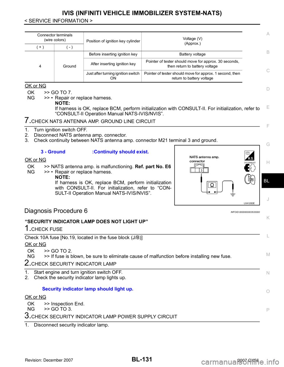
7.CHECK NATS ANTENNA AMP. GROUND LINE CIRCUIT
1. Turn ignition switch OFF.
2. Disconnect NATS antenna amp. connector.
3. Check continuity between NATS antenna amp. connector M21 terminal 3 and ground.
OK or NG
OK >> NATS antenna amp. is malfunctioning. Ref. part No. E6
NG >> • Repair or replace harness.
NOTE:
If harness is OK, replace BCM, perform initialization
with CONSULT-II. For initialization, refer to “CON-
SULT-II Operation Manual NATS-IVIS/NVIS”.
Diagnosis Procedure 6INFOID:0000000003533000
“SECURITY INDICATOR LAMP DOES NOT LIGHT UP”
1.CHECK FUSE
Check 10A fuse [No.19, located in the fuse block (J/B)]
OK or NG
OK >> GO TO 2.
NG >> If fuse is blown, be sure to eliminate cause of malfunction before installing new fuse.
2.CHECK SECURITY INDICATOR LAMP
1. Start engine and turn ignition switch OFF.
2. Check the security indicator lamp lights up.
OK or NG
OK >> Inspection End.
NG >> GO TO 3.
3.CHECK SECURITY INDICATOR LAMP POWER SUPPLY CIRCUIT
1. Disconnect security indicator lamp.
Connector terminals
(wire colors)
Position of ignition key cylinderVoltage (V)
(Approx.)
( + ) ( - )
4GroundBefore inserting ignition key Battery voltage
After inserting ignition keyPointer of tester should move for approx. 30 seconds,
then return to battery voltage
Just after turning ignition switch
ONPointer of tester should move for approx. 1 second, then
return to battery voltage
3 - Ground :Continuity should exist.
LIIA1283E
Security indicator lamp should light up.
Page 863 of 3061
BL-152
< SERVICE INFORMATION >
BODY REPAIR
Engine Compartment
LIIA1506E
Page 903 of 3061
BRAKE PEDAL
BR-5
< SERVICE INFORMATION >
C
D
E
G
H
I
J
K
L
MA
B
BR
N
O
P
BRAKE PEDAL
Inspection and AdjustmentINFOID:0000000003532722
INSPECTION
1. Inspect the brake pedal free height "H" from the lower dash panel using tool.
2. Adjust the height referring to the following specifications.
CAUTION:
When equipped with adjustable pedal, the pedal must be in
the forwardmost (closest to the floor) position for pedal
height measurement.
Brake Pedal Specifications
Unit: mm (in)
ADJUSTMENT
1. Loosen the stop lamp switch and ASCD switch by turning 45° counterclockwise. Tool number : — (J-46532)
WFIA0160E
Free height "H" : 182.3 - 192.3 mm (7.18 - 7.57 in)
Depressed pedal height "D" [under a force of 490 N (50 kg-f, 110 lb-f) with engine
running]: More than 90.3 mm (3.55 in)
Clearance between pedal stopper and threaded end of stop lamp switch and
ASCD switch "C
1 " or “C2 ”: 0.74 - 1.96 mm (0.029 - 0.077 in)
Pedal play "A" : 3 - 11 mm (0.12 - 0.43 in)
Page 904 of 3061

BR-6
< SERVICE INFORMATION >
BRAKE PEDAL
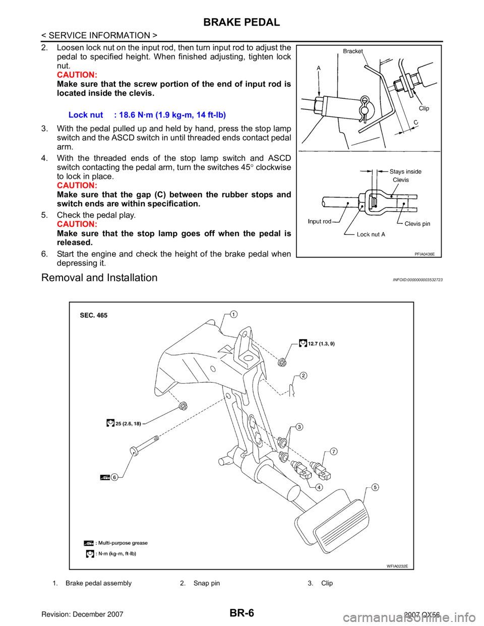
2. Loosen lock nut on the input rod, then turn input rod to adjust the
pedal to specified height. When finished adjusting, tighten lock
nut.
CAUTION:
Make sure that the screw portion of the end of input rod is
located inside the clevis.
3. With the pedal pulled up and held by hand, press the stop lamp
switch and the ASCD switch in until threaded ends contact pedal
arm.
4. With the threaded ends of the stop lamp switch and ASCD
switch contacting the pedal arm, turn the switches 45° clockwise
to lock in place.
CAUTION:
Make sure that the gap (C) between the rubber stops and
switch ends are within specification.
5. Check the pedal play.
CAUTION:
Make sure that the stop lamp goes off when the pedal is
released.
6. Start the engine and check the height of the brake pedal when
depressing it.
Removal and InstallationINFOID:0000000003532723
Lock nut : 18.6 N·m (1.9 kg-m, 14 ft-lb)
PFIA0436E
1. Brake pedal assembly 2. Snap pin 3. Clip
WFIA0232E