Page 2613 of 3061

REAR SUSPENSION ASSEMBLY
RSU-23
< SERVICE INFORMATION >
C
D
F
G
H
I
J
K
L
MA
B
RSU
N
O
P
Wheel AlignmentInspectionINFOID:0000000003532671
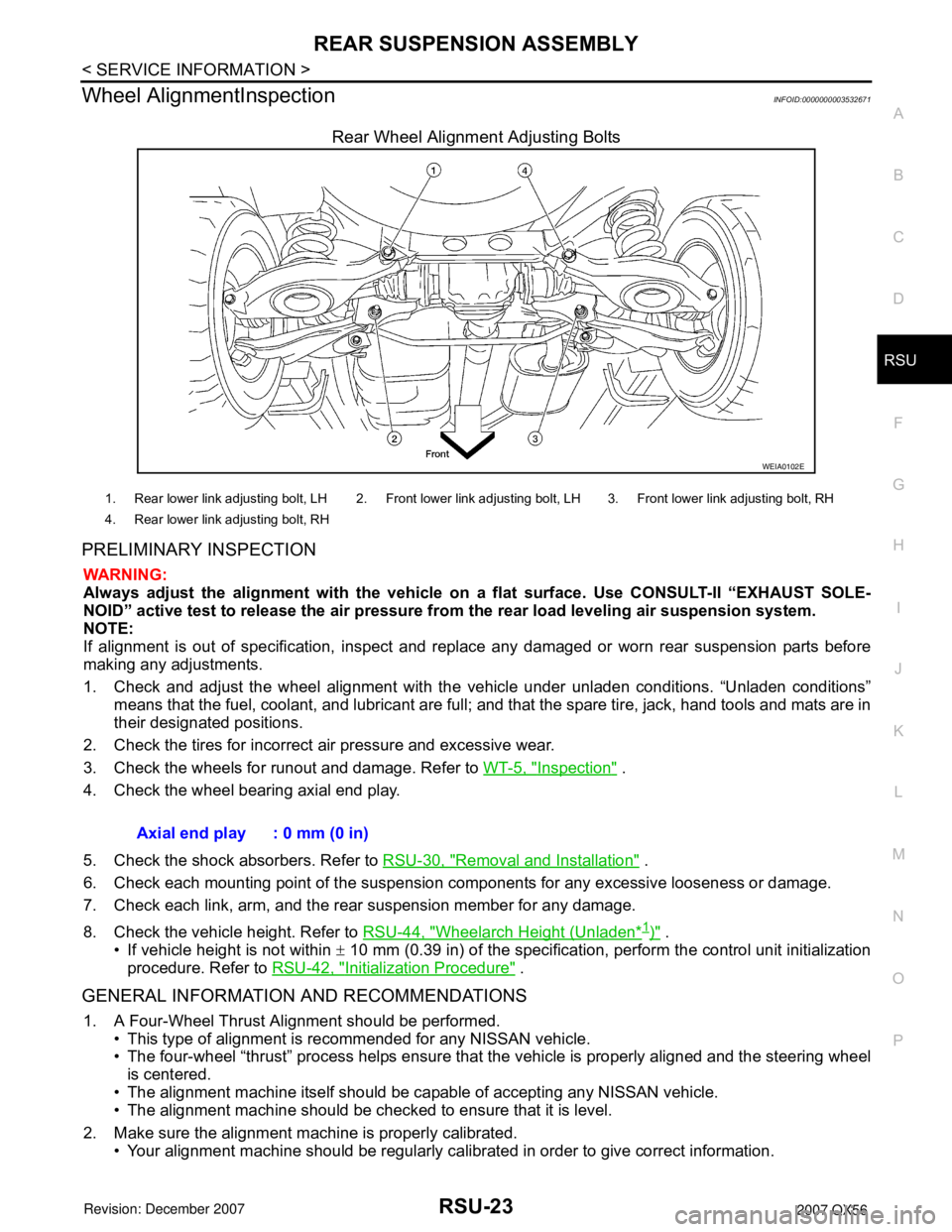
Rear Wheel Alignment Adjusting Bolts
PRELIMINARY INSPECTION
WARNING:
Always adjust the alignment with the vehicle on a flat surface. Use CONSULT-II “EXHAUST SOLE-
NOID” active test to release the air pressure from the rear load leveling air suspension system.
NOTE:
If alignment is out of specification, inspect and replace any damaged or worn rear suspension parts before
making any adjustments.
1. Check and adjust the wheel alignment with the vehicle under unladen conditions. “Unladen conditions”
means that the fuel, coolant, and lubricant are full; and that the spare tire, jack, hand tools and mats are in
their designated positions.
2. Check the tires for incorrect air pressure and excessive wear.
3. Check the wheels for runout and damage. Refer to WT-5, "
Inspection" .
4. Check the wheel bearing axial end play.
5. Check the shock absorbers. Refer to RSU-30, "
Removal and Installation" .
6. Check each mounting point of the suspension components for any excessive looseness or damage.
7. Check each link, arm, and the rear suspension member for any damage.
8. Check the vehicle height. Refer to RSU-44, "
Wheelarch Height (Unladen*1)" .
• If vehicle height is not within ± 10 mm (0.39 in) of the specification, perform the control unit initialization
procedure. Refer to RSU-42, "
Initialization Procedure" .
GENERAL INFORMATION AND RECOMMENDATIONS
1. A Four-Wheel Thrust Alignment should be performed.
• This type of alignment is recommended for any NISSAN vehicle.
• The four-wheel “thrust” process helps ensure that the vehicle is properly aligned and the steering wheel
is centered.
• The alignment machine itself should be capable of accepting any NISSAN vehicle.
• The alignment machine should be checked to ensure that it is level.
2. Make sure the alignment machine is properly calibrated.
• Your alignment machine should be regularly calibrated in order to give correct information.
WEIA0102E
1. Rear lower link adjusting bolt, LH 2. Front lower link adjusting bolt, LH 3. Front lower link adjusting bolt, RH
4. Rear lower link adjusting bolt, RH
Axial end play : 0 mm (0 in)
Page 2684 of 3061

SE-12
< SERVICE INFORMATION >
AUTOMATIC DRIVE POSITIONER
NOTE:
• Disconnecting the battery erases the stored memory.
• After connecting the battery, insert the key into the ignition cylinder and turn the front door switch LH ON (open)→OFF (close)→ON
(open), the entry/exiting function becomes possible.
• After Exiting operation is carried out, return operation can be operated.
NOTE:
During automatic operation, if the ignition switch is turned ON→START, the automatic operation is suspended. When the ignition switch
returns to ON, it resumes.
FA I L - S A F E M O D E
When any manual and automatic operations are not performed, if any motor operations of seats or pedals are
detected for T2 or more, status is judged “Output error”.
CANCEL OF FAIL-SAFE MODE
The mode is cancelled when the A/T selector lever is shifted to P position from any other position.
NOTE:
The front seat LH position and pedal adjustment functions (see the following table) operate simultaneously in
the order of priority.
*: In conjunction with sliding the seat, the door mirrors are positioned.Function Description
Memory operation The front seat LH, steering wheel, pedals (accelerator, brake) and door mirrors move
to the stored driving position by pushing seat memory switch (1 or 2).
Entry/exit-
ing functionExiting operation At exit, the seat moves backward and the steering wheel raises. (Exiting position)
Entry operationAt entry, the seat and steering wheel return from exiting position to the previous driving
position before the exiting operation.
Keyfob interlock operationPerform memory operation, turnout operation and return operation by pressing keyfob
unlock button.
Auto operation temporary stop
conditions.When ignition switch is turned to START during seat memory switch operation and return
operation, seat memory switch operation and return operation is stopped.
Auto operation stop conditions.• When the vehicle speed becomes 7 km/h (4 MPH) or higher (memory switch operation
and entry operation).
• When the setting switch, seat memory switch 1, or 2 are pressed.
• When A/T selector lever is in any position other than P.
• When the door mirror remote control switch is operated (when ignition switch turned to
ON).
• When power seat switch turned ON.
• When pedal adjusting switch turned ON.
• When front seat sliding entry/exiting setting is OFF (entry/exiting operation).
OPERATED PORTION T2
Seat sliding Approx. 0.1 sec.
Seat reclining Same as above
Seat lifting (Front) Same as above
Seat lifting (Rear) Same as above
Steering wheel Same as above
Pedal adjust Same as above
Priority Function Priority Function
1 Seat sliding, (door mirror LH/RH)* 4 Seat reclining
2 Pedal 5 Seat lifter-FR
3 Steering wheel 6 Seat lifter-RR
Page 2808 of 3061

SRS-38
< SERVICE INFORMATION >
SPIRAL CABLE
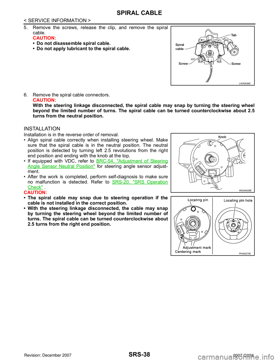
5. Remove the screws, release the clip, and remove the spiral
cable.
CAUTION:
• Do not disassemble spiral cable.
• Do not apply lubricant to the spiral cable.
6. Remove the spiral cable connectors.
CAUTION:
With the steering linkage disconnected, the spiral cable may snap by turning the steering wheel
beyond the limited number of turns. The spiral cable can be turned counterclockwise about 2.5
turns from the neutral position.
INSTALLATION
Installation is in the reverse order of removal.
• Align spiral cable correctly when installing steering wheel. Make
sure that the spiral cable is in the neutral position. The neutral
position is detected by turning left 2.5 revolutions from the right
end position and ending with the knob at the top.
• If equipped with VDC, refer to BRC-54, "
Adjustment of Steering
Angle Sensor Neutral Position" for steering angle sensor adjust-
ment.
• After the work is completed, perform self-diagnosis to make sure
no malfunction is detected. Refer to SRS-20, "
SRS Operation
Check" .
CAUTION:
• The spiral cable may snap due to steering operation if the
cable is not installed in the correct position.
• With the steering linkage disconnected, the cable may snap
by turning the steering wheel beyond the limited number of
turns. The spiral cable can be turned counterclockwise about
2.5 turns from the right end position.
LHIA0036E
WGIA0038E
PHIA0275E
Page 3016 of 3061
REMOVAL AND INSTALLATION
WT-27
< SERVICE INFORMATION >
C
D
F
G
H
I
J
K
L
MA
B
WT
N
O
P
3. Place wheel on turntable of tire machine. Ensure that transmitter
is 270 degrees from mounting/dismounting head.
NOTE:
Do not touch transmitter with mounting head.
4. Lubricate tire well, and install second side of tire as normal.
Ensure that tire does not rotate relative to rim.
5. Inflate tire and balance the wheel and tire assembly. Refer to
WT-6, "
Balancing Wheels" .
6. Install Wheel and tire assembly in appropriate wheel position on
vehicle.
NOTE:
If replacing the transmitter, then transmitter wake up operation
must be performed. Refer to WT-14, "
Transmitter Wake Up Operation" .
7. Adjust neutral position of steering angle sensor. Refer to BRC-54, "
Adjustment of Steering Angle Sensor
Neutral Position" .
SEIA0048E