Page 2389 of 3061

CHASSIS AND BODY MAINTENANCE
MA-27
< SERVICE INFORMATION >
C
D
E
F
G
H
I
J
K
MA
B
MA
N
O
P
5. Start wheel balancer. Make sure that inner and outer residual imbalance values are 5 g (0.18 oz) each or
below.
Wheel Balance (Maximum Allowable Imbalance)
• If either residual imbalance value exceeds 5 g (0.18 oz), repeat installation procedures.
Tire RotationINFOID:0000000003533885
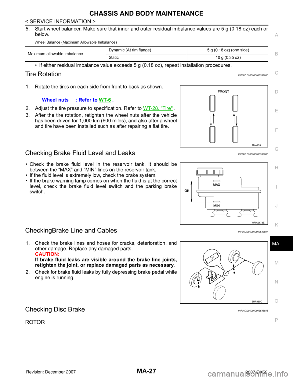
1. Rotate the tires on each side from front to back as shown.
2. Adjust the tire pressure to specification. Refer to WT-28, "
Tire" .
3. After the tire rotation, retighten the wheel nuts after the vehicle
has been driven for 1,000 km (600 miles), and also after a wheel
and tire have been installed such as after repairing a flat tire.
Checking Brake Fluid Level and LeaksINFOID:0000000003533886
• Check the brake fluid level in the reservoir tank. It should be
between the “MAX” and “MIN” lines on the reservoir tank.
• If the fluid level is extremely low, check the brake system.
• If the brake warning lamp comes on when the fluid is at the correct
level, check the brake fluid level switch and the parking brake
switch.
CheckingBrake Line and CablesINFOID:0000000003533887
1. Check the brake lines and hoses for cracks, deterioration, and
other damage. Replace any damaged parts.
CAUTION:
If brake fluid leaks are visible around the brake line joints,
retighten the joint, or replace damaged parts as necessary.
2. Check for brake fluid leaks by fully depressing brake pedal while
engine is running.
Checking Disc BrakeINFOID:0000000003533888
ROTOR
Maximum allowable imbalanceDynamic (At rim flange) 5 g (0.18 oz) (one side)
Static 10 g (0.35 oz)
Wheel nuts : Refer to WT-6 .
AMA159
WFIA0173E
SBR389C
Page 2391 of 3061

CHASSIS AND BODY MAINTENANCE
MA-29
< SERVICE INFORMATION >
C
D
E
F
G
H
I
J
K
MA
B
MA
N
O
P
• Check the power steering fluid level with the engine off.
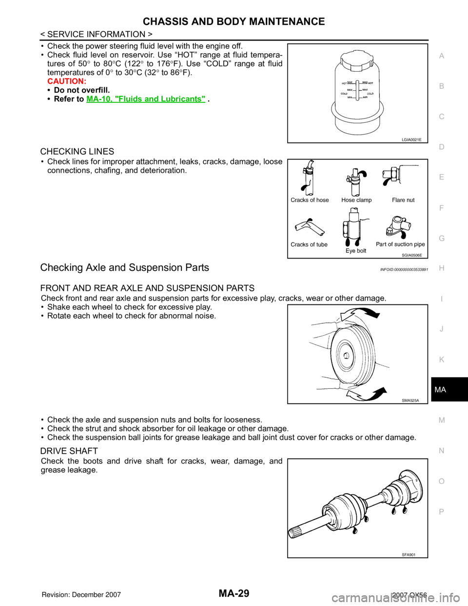
• Check fluid level on reservoir. Use “HOT” range at fluid tempera-
tures of 50° to 80°C (122° to 176°F). Use “COLD” range at fluid
temperatures of 0° to 30°C (32° to 86°F).
CAUTION:
• Do not overfill.
• Refer to MA-10, "
Fluids and Lubricants" .
CHECKING LINES
• Check lines for improper attachment, leaks, cracks, damage, loose
connections, chafing, and deterioration.
Checking Axle and Suspension PartsINFOID:0000000003533891
FRONT AND REAR AXLE AND SUSPENSION PARTS
Check front and rear axle and suspension parts for excessive play, cracks, wear or other damage.
• Shake each wheel to check for excessive play.
• Rotate each wheel to check for abnormal noise.
• Check the axle and suspension nuts and bolts for looseness.
• Check the strut and shock absorber for oil leakage or other damage.
• Check the suspension ball joints for grease leakage and ball joint dust cover for cracks or other damage.
DRIVE SHAFT
Check the boots and drive shaft for cracks, wear, damage, and
grease leakage.
LGIA0021E
SGIA0506E
SMA525A
SFA901
Page 2396 of 3061

PARKING BRAKE SYSTEM
PB-3
< SERVICE INFORMATION >
C
D
E
G
H
I
J
K
L
MA
B
PB
N
O
P
PARKING BRAKE SYSTEM
On-Vehicle ServiceINFOID:0000000003532755
PEDAL STROKE
• When parking brake pedal is operated with the specified force, make sure the stroke is within the specified
number of notches. Check by listening and counting the ratchet clicks.
INSPECTION
• Make sure the components are attached properly, checking for looseness or backlash.
• Check parking brake pedal assembly for bends, damage and cracks, and replace if necessary.
• Check cable for wear and damage, and replace if necessary.
• Check parking brake warning lamp switch for malfunction, and replace if necessary. Refer to DI-27, "
Wiring
Diagram - WARN -".
ADJUSTMENT
1. Remove the lower instrument panel LH. Refer to IP-10, "Removal and Installation" .
2. Partially engage parking brake pedal to access adjusting nut.
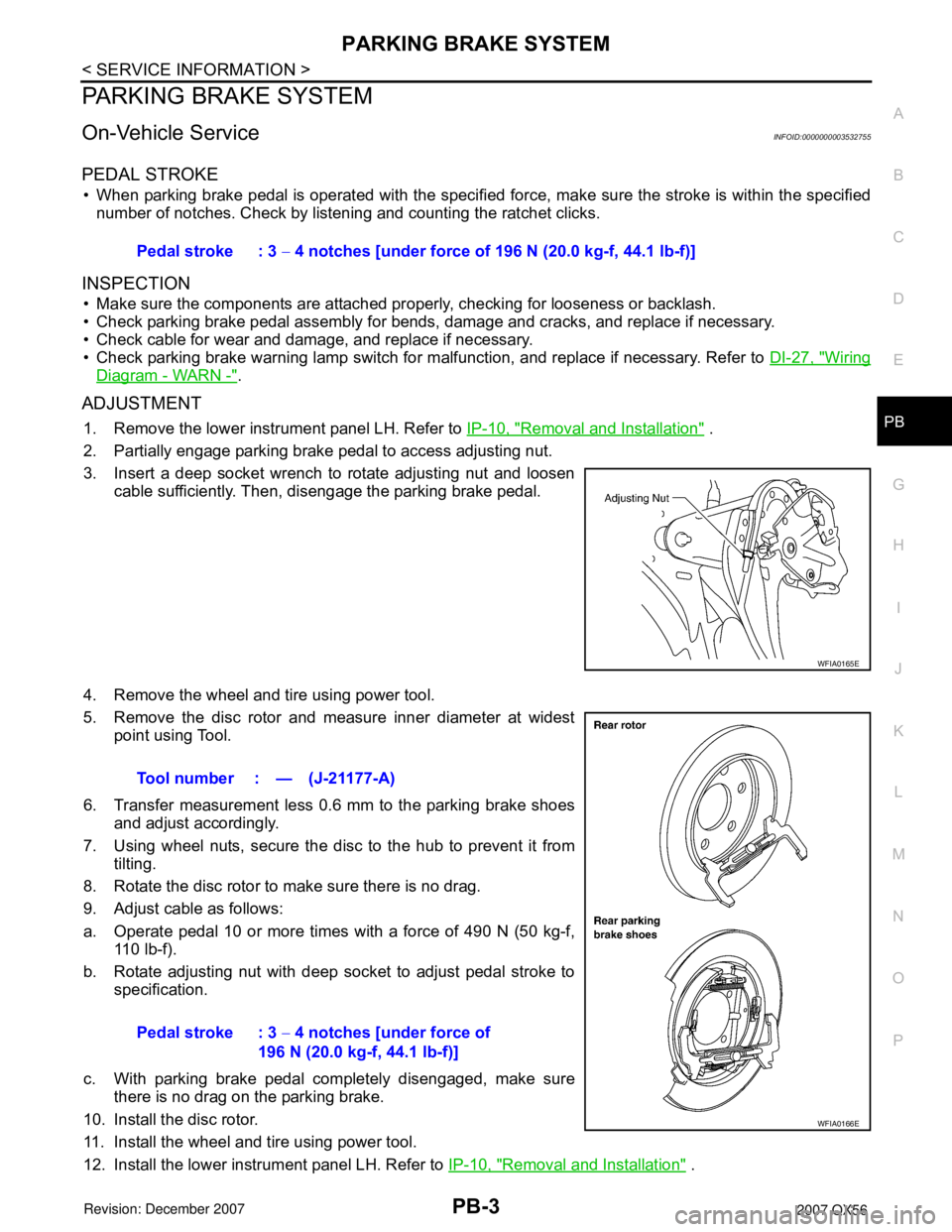
3. Insert a deep socket wrench to rotate adjusting nut and loosen
cable sufficiently. Then, disengage the parking brake pedal.
4. Remove the wheel and tire using power tool.
5. Remove the disc rotor and measure inner diameter at widest
point using Tool.
6. Transfer measurement less 0.6 mm to the parking brake shoes
and adjust accordingly.
7. Using wheel nuts, secure the disc to the hub to prevent it from
tilting.
8. Rotate the disc rotor to make sure there is no drag.
9. Adjust cable as follows:
a. Operate pedal 10 or more times with a force of 490 N (50 kg-f,
110 lb-f).
b. Rotate adjusting nut with deep socket to adjust pedal stroke to
specification.
c. With parking brake pedal completely disengaged, make sure
there is no drag on the parking brake.
10. Install the disc rotor.
11. Install the wheel and tire using power tool.
12. Install the lower instrument panel LH. Refer to IP-10, "
Removal and Installation" . Pedal stroke : 3 − 4 notches [under force of 196 N (20.0 kg-f, 44.1 lb-f)]
WFIA0165E
Tool number : — (J-21177-A)
Pedal stroke : 3 − 4 notches [under force of
196 N (20.0 kg-f, 44.1 lb-f)]
WFIA0166E
Page 2399 of 3061
PB-6
< SERVICE INFORMATION >
PARKING BRAKE SHOE
PARKING BRAKE SHOE
Removal and InstallationINFOID:0000000003532758
COMPONENTS
REMOVAL
WARNING:
Clean the brakes with a vacuum dust collector to minimize the hazard of airborne particles or other
materials.
NOTE:
Remove the disc rotor only with the parking brake pedal completely disengaged.
1. Remove wheel hub and bearing assembly. Refer to FA X - 5 , "
Removal and Installation" .
• Disconnect the wheel sensor at the harness connector. It is not necessary to remove the wheel sensor
from the wheel hub and bearing assembly.
2. Remove the return springs.
3. Remove the adjuster.
4. Remove the retainers, anti-rattle pins and shoes.
5. Disconnect the rear cable from the toggle lever.
6. Remove the back plate.
INSPECTION AFTER REMOVAL
Lining Thickness Inspection
1. Back plate 2. Shoes 3. Toggle lever
4. Return springs 5. Retainers 6. Adjuster
7. Anti-rattle pins
WFIA0164E
Page 2480 of 3061

NOISE, VIBRATION AND HARSHNESS (NVH) TROUBLESHOOTINGPR-3
< SERVICE INFORMATION >
CEF
G H
I
J
K L
M A
B
PR
N
O P
NOISE, VIBRATION AND HARSHN ESS (NVH) TROUBLESHOOTING
NVH Troubleshooting ChartINFOID:0000000003532575
Use the chart below to help you find t he cause of the symptom. If necessary, repair or replace these parts.
×: ApplicableReference page
PR-4
(front)
PR-8 (rear)
PR-4 (front)
PR-8 (rear)
PR-4 (front)
PR-8 (rear)
FFD-6, "
NVH Troubleshooting Chart
"
RFD-7, "
NVH Troubleshooting Chart
"
FAX-4, "
NVH Troubleshooting Chart
"
RAX-4, "
NVH Troubleshooting Chart
"
FSU-4, "
NVH Troubleshooting Chart
"
RSU-4, "
NVH Troubleshooting Chart
"
WT-4, "
NVH Troubleshooting Chart
"
WT-4, "
NVH Troubleshooting Chart
"
FAX-4, "
NVH Troubleshooting Chart
"
BR-4, "
NVH Troubleshooting Chart
"
PS-5, "
NVH Troubleshooting Chart
"
Possible cause and suspected parts
Uneven rotation torque
Rotation imbalance
Excessive run out
Differential
Axle
Suspension
Tires
Road wheel
Drive shaft
Brakes
Ste eri ng
Symptom Noise
×××××××××××
Shake ×××××××
Vibration ××××××××
Page 2492 of 3061

PS-1
STEERING
C
D
E
F
H
I
J
K
L
M
SECTION PS
A
B
PS
N
O
P
CONTENTS
POWER STEERING SYSTEM
SERVICE INFORMATION ............................2
PRECAUTIONS ...................................................2
Precaution for Supplemental Restraint System
(SRS) "AIR BAG" and "SEAT BELT PRE-TEN-
SIONER" ...................................................................
2
Precaution for Steering System ................................2
PREPARATION ...................................................3
Special Service Tool .................................................3
Commercial Service Tool ..........................................4
NOISE, VIBRATION AND HARSHNESS
(NVH) TROUBLESHOOTING .............................
5
NVH Troubleshooting Chart ......................................5
POWER STEERING FLUID ................................6
Checking Fluid Level .................................................6
Checking Fluid Leakage ............................................6
Air Bleeding Hydraulic System ..................................6
STEERING WHEEL .............................................7
On-Vehicle Inspection and Service ...........................7
Removal and Installation ...........................................8
TILT SYSTEM ......................................................9
Removal and Installation ..........................................9
STEERING COLUMN ........................................10
Removal and Installation .........................................10
Disassembly and Assembly .....................................13
POWER STEERING GEAR AND LINKAGE ....15
Removal and Installation .........................................15
Disassembly and Assembly .....................................17
POWER STEERING OIL PUMP .......................21
On-Vehicle Inspection and Service .........................21
Removal and Installation .........................................21
Disassembly and Assembly .....................................22
HYDRAULIC LINE ............................................23
Removal and Installation .........................................23
SERVICE DATA AND SPECIFICATIONS
(SDS) .................................................................
25
Steering Wheel ........................................................25
Steering Column ......................................................25
Steering Outer Socket and Inner Socket .................26
Steering Gear ..........................................................26
Oil Pump ..................................................................27
Steering Fluid ..........................................................27
Page 2494 of 3061

PREPARATION
PS-3
< SERVICE INFORMATION >
C
D
E
F
H
I
J
K
L
MA
B
PS
N
O
P
PREPARATION
Special Service ToolINFOID:0000000003532818
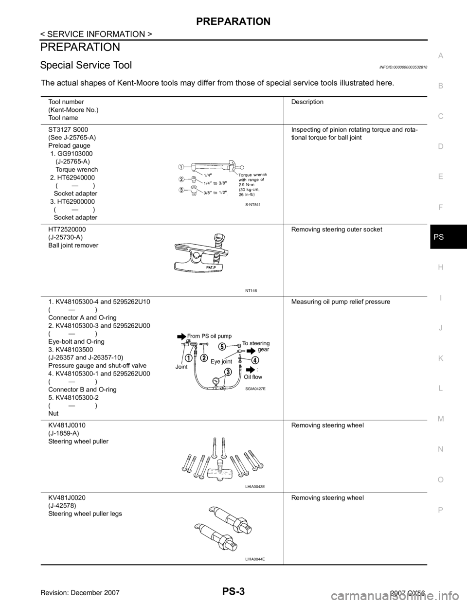
The actual shapes of Kent-Moore tools may differ from those of special service tools illustrated here.
Tool number
(Kent-Moore No.)
Tool nameDescription
ST3127 S000
(See J-25765-A)
Preload gauge
1. GG9103000
(J-25765-A)
Torque wrench
2. HT62940000
( — )
Socket adapter
3. HT62900000
( — )
Socket adapterInspecting of pinion rotating torque and rota-
tional torque for ball joint
HT72520000
(J-25730-A)
Ball joint removerRemoving steering outer socket
1. KV48105300-4 and 5295262U10
( — )
Connector A and O-ring
2. KV48105300-3 and 5295262U00
( — )
Eye-bolt and O-ring
3. KV48103500
(J-26357 and J-26357-10)
Pressure gauge and shut-off valve
4. KV48105300-1 and 5295262U00
( — )
Connector B and O-ring
5. KV48105300-2
( — )
NutMeasuring oil pump relief pressure
KV481J0010
(J-1859-A)
Steering wheel pullerRemoving steering wheel
KV481J0020
(J-42578)
Steering wheel puller legsRemoving steering wheel
S-NT541
NT146
SGIA0427E
LHIA0043E
LHIA0044E
Page 2495 of 3061
PS-4
< SERVICE INFORMATION >
PREPARATION
Commercial Service Tool
INFOID:0000000003532819
KV40107300
(—)Crimping boot bands
—
(J-44372)
Spring gaugeMeasuring steering wheel turning force Tool number
(Kent-Moore No.)
Tool nameDescription
ZZA1229D
LST024
Tool nameDescription
Power toolRemoving nuts and bolts
PBIC0190E