Page 2796 of 3061

SRS-26
< SERVICE INFORMATION >
TROUBLE DIAGNOSIS
NOTE:
Follow the procedures in numerical order when repairing malfunctioning parts. Confirm whether malfunction is
eliminated using air bag warning lamp or CONSULT-II each time repair is finished. If malfunction is still
observed, proceed to the next step. When malfunction is eliminated, further repair work is not required.
DIAGNOSTIC PROCEDURE 3
Final Check of SRS Using CONSULT-II—Diagnosis Mode
Refer to GI-36, "CONSULT-II Start Procedure" .
OCCUPANT SENS C/U
[COMM FAIL]
[B1022]Communication between the occupant classification system
control unit and air bag diagnosis sensor unit is interrupted.1. Visually check the wiring harness
connection.
2. Replace the harness if it has visi-
ble damage.
3. Replace RH front seat cushion/
occupant classification system
control unit assembly.
4. Replace the air bag diagnosis
sensor unit.
5. Replace the related harness.
OCCUPANT SENS
[UNIT FAIL]
[B1018]Occupant classification sensor is malfunctioning. 1. Replace RH front seat cushion/
occupant classification system
control unit assembly.
BELT TENSION SENS
[UNIT FAIL]
[B1019]Belt tension sensor is malfunctioning. 1. Visually check the wiring harness
connection.
2. Replace the harness if it has visi-
ble damage.
3. Replace RH front seat belt as-
sembly.
4. Replace RH front seat cushion/
occupant classification system
control unit assembly.
5. Replace the related harness.
PASS A/B INDCTR CKT
[B1023]Front passenger air bag off indicator is malfunctioning. 1. Visually check the wiring harness
connection.
2. Replace the harness if it has visi-
ble damage.
3. Replace front passenger air bag
off indicator.
4. Replace the air bag diagnosis
sensor unit.
5. Replace the related harness.
FRONTAL COLLISION
DETECTION
[B1209]Driver and front passenger air bag modules are deployed. 1. Refer to SRS-49
.
SIDE COLLISION
DETECTION
[B1210]Side or curtain air bag modules are deployed (with side air
bags only).
ROLLOVER DETECTION
[B1211]Curtain air bag module and seat belt pre-tensioner are de-
ployed. Diagnostic item ExplanationRepair order
Recheck SRS at each replacement
Page 2803 of 3061

TROUBLE DIAGNOSIS
SRS-33
< SERVICE INFORMATION >
C
D
E
F
G
I
J
K
L
MA
B
SRS
N
O
P
1.CHECK CONDITION OF AIR BAG MODULE
Inspect for any deployed air bag modules or seat belt pre-tensioners.
Are any air bag modules or seat belt pre-tensioners deployed?
Yes >> Refer to SRS-49 .
No >> GO TO 2.
2.CHECK THE AIR BAG FUSE
Check 10A fuse [No. 13, located in the fuse block (J/B)].
Refer to PG-3
.
OK or NG
OK >> GO TO 4.
NG >> GO TO 3.
3.CHECK AIR BAG FUSE AGAIN
Replace 10A fuse [No. 13, located in the fuse block (J/B)] and turn ignition switch ON.
Does the fuse blow again?
Yes >> Repair harness.
No >> Inspection End.
4.CHECK AIR BAG DIAGNOSIS SENSOR UNIT
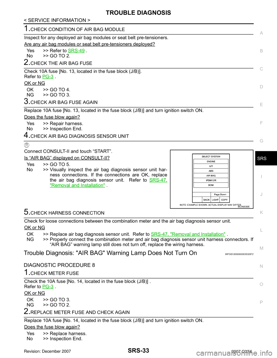
Connect CONSULT-II and touch “START”.
Is
“AIR BAG” displayed on CONSULT-II?
Yes >> GO TO 5.
No >> Visually inspect the air bag diagnosis sensor unit har-
ness connections. If the connections are OK, replace
the air bag diagnosis sensor unit. Refer to SRS-47,
"Removal and Installation" .
5.CHECK HARNESS CONNECTION
Check for loose connections between the combination meter and the air bag diagnosis sensor unit.
OK or NG
OK >> Replace air bag diagnosis sensor unit. Refer to SRS-47, "Removal and Installation" .
NG >> Properly connect the combination meter and air bag diagnosis sensor unit harness connectors. If
“AIR BAG” warning lamp still does not turn off, replace the wiring harness.
Trouble Diagnosis: "AIR BAG" Warning Lamp Does Not Turn OnINFOID:0000000003532872
DIAGNOSTIC PROCEDURE 8
1.CHECK METER FUSE
Check the 10A fuse [No. 14, located in the fuse block (J/B)] .
Refer to PG-3
.
OK or NG
OK >> GO TO 3.
NG >> GO TO 2.
2.REPLACE METER FUSE AND CHECK AGAIN
Replace 10A fuse [No. 14, located in the fuse block (J/B)] and turn ignition switch ON.
Does the fuse blow again?
Yes >> Replace harness.
No >> Inspection End.
BCIA0030E
Page 2804 of 3061
SRS-34
< SERVICE INFORMATION >
TROUBLE DIAGNOSIS
3.CHECK HARNESS CONNECTIONS BETWEEN AIR BAG DIAGNOSIS SENSOR UNIT AND COMBINA-
TION METER
Inspect the harness and connectors between the air bag diagnosis sensor unit and the combination meter.
Do the harness or connectors have any visible damage?
Yes >> Replace harness.
No >> GO TO 4.
4.CHECK COMBINATION METER
Disconnect the air bag diagnosis sensor unit harness connectors and turn ignition switch ON.
Does
“AIR BAG” warning lamp turn on?
Yes >> Replace the air bag diagnosis sensor unit. Refer to SRS-47, "Removal and Installation" .
No >> Replace the combination meter. Refer to IP-10, "
Removal and Installation" .
Page 2808 of 3061

SRS-38
< SERVICE INFORMATION >
SPIRAL CABLE
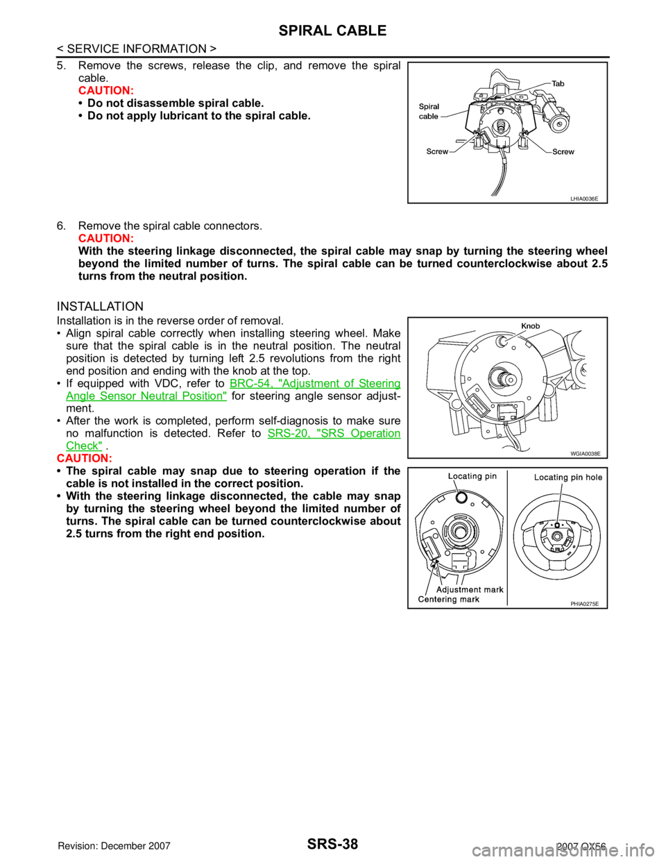
5. Remove the screws, release the clip, and remove the spiral
cable.
CAUTION:
• Do not disassemble spiral cable.
• Do not apply lubricant to the spiral cable.
6. Remove the spiral cable connectors.
CAUTION:
With the steering linkage disconnected, the spiral cable may snap by turning the steering wheel
beyond the limited number of turns. The spiral cable can be turned counterclockwise about 2.5
turns from the neutral position.
INSTALLATION
Installation is in the reverse order of removal.
• Align spiral cable correctly when installing steering wheel. Make
sure that the spiral cable is in the neutral position. The neutral
position is detected by turning left 2.5 revolutions from the right
end position and ending with the knob at the top.
• If equipped with VDC, refer to BRC-54, "
Adjustment of Steering
Angle Sensor Neutral Position" for steering angle sensor adjust-
ment.
• After the work is completed, perform self-diagnosis to make sure
no malfunction is detected. Refer to SRS-20, "
SRS Operation
Check" .
CAUTION:
• The spiral cable may snap due to steering operation if the
cable is not installed in the correct position.
• With the steering linkage disconnected, the cable may snap
by turning the steering wheel beyond the limited number of
turns. The spiral cable can be turned counterclockwise about
2.5 turns from the right end position.
LHIA0036E
WGIA0038E
PHIA0275E
Page 2814 of 3061
SRS-44
< SERVICE INFORMATION >
CRASH ZONE SENSOR
CRASH ZONE SENSOR
Removal and InstallationINFOID:0000000003532877
REMOVAL
CAUTION:
• Before servicing the SRS, turn the ignition switch off, disconnect both battery cables and wait at
least 3 minutes.
1. Disconnect the negative and positive battery cables, then wait at least 3 minutes.
2. Remove front grille. Refer to EI-16
.
3. Disconnect the crash zone sensor harness connector.
4. Remove crash zone sensor nuts.
CAUTION:
• Replace crash zone sensor if it has been dropped or sustained an impact.
• Do not disassemble crash zone sensor.
INSTALLATION
Installation is in the reverse order of removal.
• After the work is complete, perform self-diagnosis to check that no malfunction is detected. Refer to SRS-20,
"SRS Operation Check" .
LHIA0056E
Page 2815 of 3061

SIDE AIR BAG (SATELLITE) SENSOR
SRS-45
< SERVICE INFORMATION >
C
D
E
F
G
I
J
K
L
MA
B
SRS
N
O
P
SIDE AIR BAG (SATELLITE) SENSOR
Removal and InstallationINFOID:0000000003532878
REMOVAL
CAUTION:
• Before servicing the SRS, turn the ignition switch off, disconnect both battery cables and wait at
least 3 minutes.
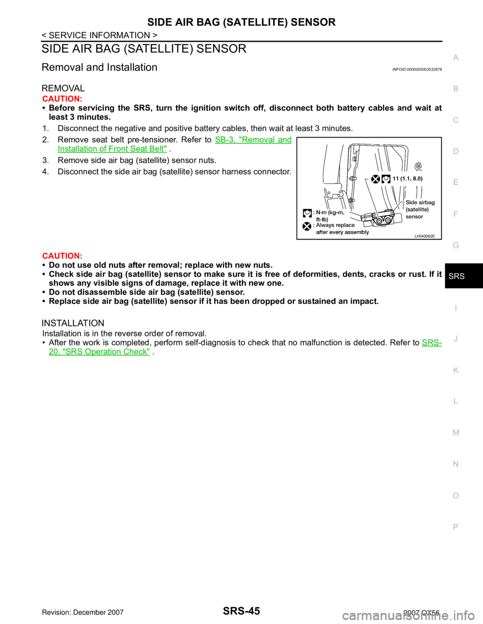
1. Disconnect the negative and positive battery cables, then wait at least 3 minutes.
2. Remove seat belt pre-tensioner. Refer to SB-3, "
Removal and
Installation of Front Seat Belt" .
3. Remove side air bag (satellite) sensor nuts.
4. Disconnect the side air bag (satellite) sensor harness connector.
CAUTION:
• Do not use old nuts after removal; replace with new nuts.
• Check side air bag (satellite) sensor to make sure it is free of deformities, dents, cracks or rust. If it
shows any visible signs of damage, replace it with new one.
• Do not disassemble side air bag (satellite) sensor.
• Replace side air bag (satellite) sensor if it has been dropped or sustained an impact.
INSTALLATION
Installation is in the reverse order of removal.
• After the work is completed, perform self-diagnosis to check that no malfunction is detected. Refer to SRS-
20, "SRS Operation Check" .
LHIA0062E
Page 2817 of 3061

DIAGNOSIS SENSOR UNIT
SRS-47
< SERVICE INFORMATION >
C
D
E
F
G
I
J
K
L
MA
B
SRS
N
O
P
DIAGNOSIS SENSOR UNIT
Removal and InstallationINFOID:0000000003532880
REMOVAL
CAUTION:
• Before servicing the SRS, turn the ignition switch off, disconnect both battery cables and wait at
least 3 minutes.
1. Disconnect the negative and positive battery cables, then wait at least 3 minutes.
2. Disconnect the harness connectors for each air bag module and seat belt pre-tensioner.
3. Remove center console. Refer to IP-10
.
4. Disconnect diagnosis sensor unit harness connectors.
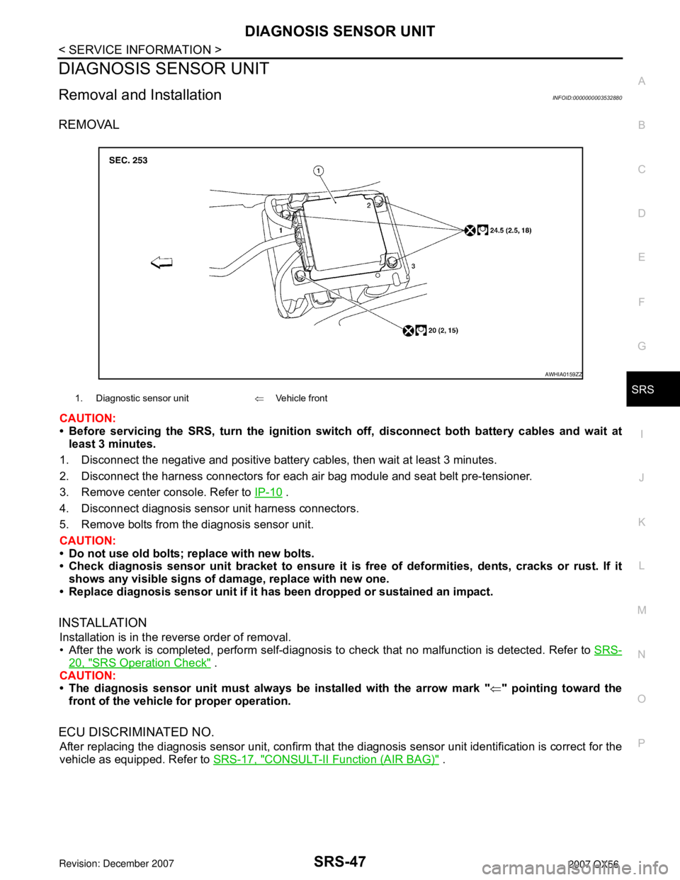
5. Remove bolts from the diagnosis sensor unit.
CAUTION:
• Do not use old bolts; replace with new bolts.
• Check diagnosis sensor unit bracket to ensure it is free of deformities, dents, cracks or rust. If it
shows any visible signs of damage, replace with new one.
• Replace diagnosis sensor unit if it has been dropped or sustained an impact.
INSTALLATION
Installation is in the reverse order of removal.
• After the work is completed, perform self-diagnosis to check that no malfunction is detected. Refer to SRS-
20, "SRS Operation Check" .
CAUTION:
• The diagnosis sensor unit must always be installed with the arrow mark "⇐" pointing toward the
front of the vehicle for proper operation.
ECU DISCRIMINATED NO.
After replacing the diagnosis sensor unit, confirm that the diagnosis sensor unit identification is correct for the
vehicle as equipped. Refer to SRS-17, "
CONSULT-II Function (AIR BAG)" .
1. Diagnostic sensor unit⇐Vehicle front
AWHIA0159ZZ
Page 2818 of 3061
SRS-48
< SERVICE INFORMATION >
OCCUPANT CLASSIFICATION SYSTEM CONTROL UNIT
OCCUPANT CLASSIFICATION SYSTEM CONTROL UNIT
Removal and InstallationINFOID:0000000003532881
The occupant classification control unit, occupant classification (pressure) sensor, and bladder are an integral
part of the front passenger seat cushion and are replaced as an assembly. Refer to SE-83, "
Removal and
Installation" to remove the seat, and SE-85, "Disassembly and Assembly" to replace the seat cushion.