Page 3840 of 4647
SERVICE DATA AND SPECIFICATIONS (SDS)
MA-41
C
D
E
F
G
H
I
J
K
MA
B
MA
Revision: 2007 April2007 M35/M45
ENGINE OIL CAPACITY (APPROXIMATE) (VK45DE)
Unit: (US qt, lmp qt)
SPARK PLUG (PLATINUM-TIPPED TYPE) (VQ35DE)
SPARK PLUG (PLATINUM-TIPPED TYPE) (VK45DE)
WHEEL BALANCE
Drain and refillWith oil filter change 5.5 (5-3/4, 4-7/8)
Without oil filter change 4.9 (5-1/8, 4-1/4)
Dry engine (Overhaul)6.7 (7-1/8, 5-7/8)
MakeNGK
Ty p eStandard PLFR5A-11
Hot PLFR4A-11
Cold PLFR6A-11
Spark plug gapNominal: 1.1mm (0.043 in)
Make NGK
TypeStandard PLFR5A-11
Hot PLFR4A-11
Cold PLFR6A-11
Spark plug gapNominal: 1.1mm (0.043 in)
Maximum allowable unbalanceDynamic (At rim flange) Less than 7 g (0.25 oz) (one side)
Static (At rim flange) Less than 14 g (0.49 oz)
Page 3841 of 4647
MA-42
SERVICE DATA AND SPECIFICATIONS (SDS)
Revision: 2007 April2007 M35/M45
Page 3842 of 4647

PB-1
PARKING BRAKE SYSTEM
F BRAKES
CONTENTS
C
D
E
G
H
I
J
K
L
M
SECTION PB
A
B
PB
Revision: 2007 April2007 M35/M45
PARKING BRAKE SYSTEM
PREPARATION ........................................................... 2
Commercial Service Tools ........................................ 2
PARKING BRAKE SYSTEM ...................................... 3
On-Vehicle Service ................................................... 3
PEDAL STROKE ................................................... 3
INSPECT COMPONENTS .................................... 3
ADJUSTMENT ...................................................... 3
PARKING BRAKE CONTROL ................................... 4
Components ............................................................. 4
Removal and Installation .......................................... 5
REMOVAL ............................................................. 5
INSTALLATION ..................................................... 5PARKING BRAKE SHOE ........................................... 6
Components ............................................................. 6
Removal and Installation .......................................... 7
REMOVAL ............................................................. 7
INSPECTION AFTER REMOVAL ......................... 7
INSTALLATION ..................................................... 8
SERVICE DATA AND SPECIFICATIONS (SDS) ........ 9
Parking Drum Brake ................................................. 9
Parking Brake Control .............................................. 9
Page 3843 of 4647
PB-2
PREPARATION
Revision: 2007 April2007 M35/M45
PREPARATIONPFP:00002
Commercial Service ToolsNFS000SZ
Tool nameDescription
Power toolLoosening bolts and nuts
PBIC0190E
Page 3844 of 4647

PARKING BRAKE SYSTEM
PB-3
C
D
E
G
H
I
J
K
L
MA
B
PB
Revision: 2007 April2007 M35/M45
PARKING BRAKE SYSTEMPFP:36010
On-Vehicle ServiceNFS000SS
PEDAL STROKE
�Operate parking brake pedal with a force of 196 N (20 kg, 44 lb), make sure pedal stroke is within the
specified number of notches. (Check it by listening and counting ratchet clicks.)
INSPECT COMPONENTS
�Make sure that the mounting conditions (looseness, backlash, etc.) of each component are normal.
�Check the following:
–Device assembly for bend, damage and cracks. Replace if there are.
–Cables and equalizer for wear and damage. Replace if there are.
–Parking brake switch. Replace if it does not work correctly.
ADJUSTMENT
�To perform adjustment operations, remove rear tires from vehicle with power tool.
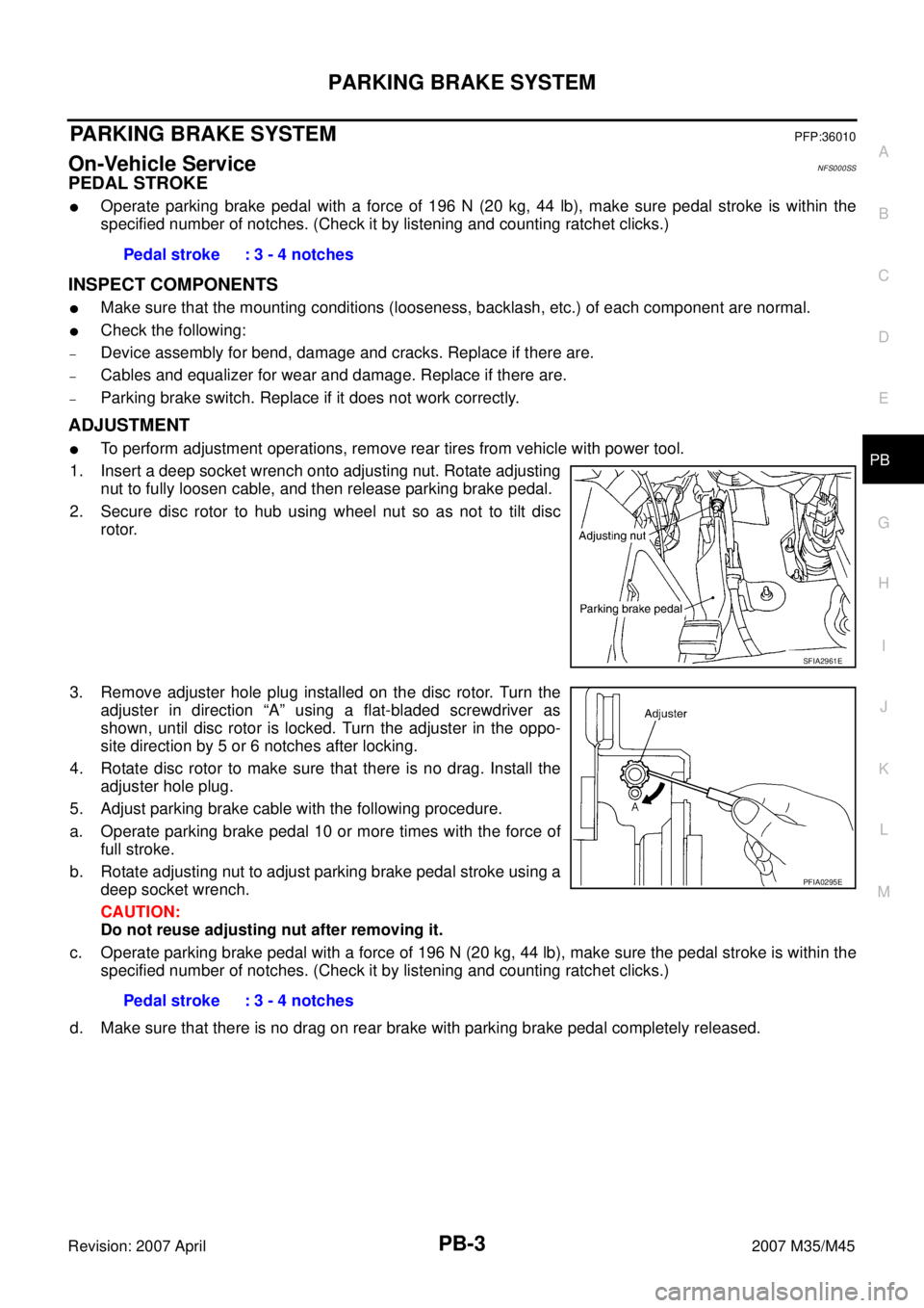
1. Insert a deep socket wrench onto adjusting nut. Rotate adjusting
nut to fully loosen cable, and then release parking brake pedal.
2. Secure disc rotor to hub using wheel nut so as not to tilt disc
rotor.
3. Remove adjuster hole plug installed on the disc rotor. Turn the
adjuster in direction “A” using a flat-bladed screwdriver as
shown, until disc rotor is locked. Turn the adjuster in the oppo-
site direction by 5 or 6 notches after locking.
4. Rotate disc rotor to make sure that there is no drag. Install the
adjuster hole plug.
5. Adjust parking brake cable with the following procedure.
a. Operate parking brake pedal 10 or more times with the force of
full stroke.
b. Rotate adjusting nut to adjust parking brake pedal stroke using a
deep socket wrench.
CAUTION:
Do not reuse adjusting nut after removing it.
c. Operate parking brake pedal with a force of 196 N (20 kg, 44 lb), make sure the pedal stroke is within the
specified number of notches. (Check it by listening and counting ratchet clicks.)
d. Make sure that there is no drag on rear brake with parking brake pedal completely released.Pedal stroke : 3 - 4 notches
SFIA2961E
Pedal stroke : 3 - 4 notches
PFIA0295E
Page 3850 of 4647
SERVICE DATA AND SPECIFICATIONS (SDS)
PB-9
C
D
E
G
H
I
J
K
L
MA
B
PB
Revision: 2007 April2007 M35/M45
SERVICE DATA AND SPECIFICATIONS (SDS)PFP:00030
Parking Drum Brake NFS000SX
Parking Brake ControlNFS000SY
Brake liningStandard thickness 3.2 mm (0.126 in)
Repair limit thickness 1.5 mm (0.059 in)
Drum (disc)Standard inner diameter 172 mm (6.77 in) dia.
Maximum inner diameter 173 mm (6.81 in) dia.
Control typeFoot pedal
Number of notches [under force of 196 N (20 kg, 44 lb)] 3 − 4 notches
Number of notches when parking brake warning lamp comes on 1 notch
Page 3851 of 4647
PB-10
SERVICE DATA AND SPECIFICATIONS (SDS)
Revision: 2007 April2007 M35/M45
Page 3968 of 4647

PR-1
PROPELLER SHAFT
D DRIVELINE/AXLE
CONTENTS
C
E
F
G
H
I
J
K
L
M
SECTION PR
A
B
PR
Revision: 2007 April2007 M35/M45
PROPELLER SHAFT
PREPARATION ........................................................... 2
Special Service Tools ............................................... 2
Commercial Service Tools ........................................ 2
NOISE, VIBRATION AND HARSHNESS (NVH)
TROUBLESHOOTING ................................................ 3
NVH Troubleshooting Chart ..................................... 3
FRONT PROPELLER SHAFT .................................... 4
On-Vehicle Inspection .............................................. 4
APPEARANCE AND NOISE INSPECTION .......... 4
PROPELLER SHAFT VIBRATION ........................ 4
Components ............................................................. 4
Removal and Installation .......................................... 5
REMOVAL ............................................................. 5
INSPECTION ........................................................ 5
INSTALLATION ..................................................... 5
REAR PROPELLER SHAFT ...................................... 6
On-Vehicle Inspection .............................................. 6APPEARANCE AND NOISE INSPECTION .......... 6
PROPELLER SHAFT VIBRATION ........................ 6
Components ............................................................. 7
Removal and Installation .......................................... 8
REMOVAL ............................................................. 8
INSPECTION ........................................................ 9
INSTALLATION ................................................... 10
Disassembly and Assembly of Center Bearing (For
3S80A-1VL107 and 3F80A-1VL107 Type) ............. 11
DISASSEMBLY ................................................... 11
ASSEMBLY ......................................................... 12
SERVICE DATA AND SPECIFICATIONS (SDS) ...... 13
General Specifications ............................................ 13
2WD MODELS .................................................... 13
AWD MODELS .................................................... 13
Journal Axial Play ................................................... 14
Propeller Shaft Runout ........................................... 14