Page 3064 of 4647

FRONT OIL SEAL
FFD-9
C
E
F
G
H
I
J
K
L
MA
B
FFD
Revision: 2007 April2007 M35/M45
FRONT OIL SEALPFP:38189
Removal and InstallationNDS000ES
REMOVAL
1. Drain gear oil. Refer to FFD-8, "DRAINING" .
2. Remove front propeller shaft. Refer to PR-5, "
Removal and Installation" .
3. Remove front drive shaft both. Refer to FA X - 11 , "
Removal and Installation" .
4. Remove side shaft assembly.
5. Remove drive pinion lock nut using a flange wrench.
6. Put matching mark (B) on the end of the drive pinion. The
matching mark (B) should be in line with the matching mark (A)
on companion flange (1).
CAUTION:
For matching mark, use paint. Do not damage companion
flange and drive pinion.
NOTE:
The matching mark (A) on the final drive companion flange (1)
indicates the maximum vertical runout position.
7. Remove companion flange using a puller.
8. Remove front oil seal using the puller.
CAUTION:
Be careful not to damage gear carrier.
PDIA0784J
PDIA0783J
PDIA0652E
Tool number A: KV381054S0 (J-34286)
PDIA0785J
Page 3065 of 4647

FFD-10
FRONT OIL SEAL
Revision: 2007 April2007 M35/M45
INSTALLATION
1. Apply multi-purpose grease to front oil seal lips.
2. Using the drifts, install front oil seal as shown in figure.
CAUTION:
�Do not reuse oil seal.
�When installing, do not incline oil seal.
3. Align the matching mark (B) of drive pinion with the matching
mark (A) of companion flange, and then install the companion
flange (1).
4. Apply anti-corrosion oil to the thread and seat of new drive pin-
ion lock nut, and temporarily tighten drive pinion lock nut to drive
pinion.
CAUTION:
Do not reuse drive pinion lock nut.
5. Tighten to drive pinion lock nut, while adjust total preload torque.
CAUTION:
�Adjust to the lower limit of the drive pinion lock nut tight-
ening torque first.
�After adjustment, rotate drive pinion back and forth 2 to 3
times to check for unusual noise, rotation malfunction,
and other malfunctions.
�If measured value is out of the specification, remove final
drive assembly and disassemble drive pinion parts to check
and adjust each part. Refer to FFD-13, "
Removal and Installa-
tion" and FFD-15, "Disassembly and Assembly" .
6. Install front propeller shaft. Refer to PR-5, "
Removal and Installation" .
7. Install side shaft assembly.
8. Install front drive shaft both. Refer to FA X - 11 , "
Removal and Installation" .
9. Refill gear oil to the final drive and check oil level. Refer to FFD-8, "
FILLING" .
10. Check the final drive for oil leakage. Refer to FFD-8, "
OIL LEAKAGE AND OIL LEVEL" . Tool number A: ST33400001 (J-26082)
B: KV38102510 ( — )
PDIA0786J
PDIA0783J
Tool number A: ST3127S000 (J-25765-A)
Drive pinion lock nut tightening torque:
127.4 - 245.0 N·m (13.0 - 25.0 kg-m, 94 - 181 ft-lb)
Total preload torque:
1.56 - 2.65 N·m (0.16 - 0.27 kg-m, 14 - 23 in-lb)
PDIA0969E
Page 3070 of 4647
FRONT FINAL DRIVE ASSEMBLY
FFD-15
C
E
F
G
H
I
J
K
L
MA
B
FFD
Revision: 2007 April2007 M35/M45
Disassembly and AssemblyNDS000EV
COMPONENTS
1. Drive pinion lock nut 2. Companion flange 3. Front oil seal
4. Pinion front bearing 5. Drive pinion bearing adjusting
washer6. Drive pinion adjusting washer
7. Gear carrier 8. Pinion rear bearing 9. Pinion height adjusting washer
10. Drive pinion 11. Drive gear 12. Side oil seal (right side)
13. Side retainer 14. O-ring 15. Side bearing adjusting shim
16. Side bearing 17. Differential case 18. Breather connector
19. Dowel pin 20. Filler plug 21. Drain plug
22. Gasket 23. Carrier cover 24. Gear oil defence
25. Side gear thrust washer 26. Side gear 27. Circular clip
28. Pinion mate thrust washer 29. Pinion mate gear 30. Pinion mate shaft
31. Lock pin 32. Side bearing adjusting washer 33. Side oil seal (left side)
PDIA0791J
Page 3071 of 4647

FFD-16
FRONT FINAL DRIVE ASSEMBLY
Revision: 2007 April2007 M35/M45
ASSEMBLY INSPECTION AND ADJUSTMENT
�Before inspection and adjustment, drain gear oil.
Total Preload Torque
1. Rotate drive pinion back and forth 2 to 3 times to check for unusual noise and rotation malfunction.
2. Rotate drive pinion at least 20 times to check for smooth opera-
tion of the bearing.
3. Measure total preload with preload gauge.
NOTE:
Total preload torque = Pinion bearing preload torque + Side
bearing preload torque
�If measured value is out of the specification, disassemble it to
check and adjust each part. Adjust the pinion bearing preload and side bearing preload.
Adjust the pinion bearing preload first, then adjust the side bearing preload.
34. Side shaft bearing 35. Extension tube retainer 36. Side shaft oil seal
37. Dust sealed 38. Side shaft
A: Oil seal lip
B: Screw hole
Refer to GI-11, "
Components" and the followings for the symbols in the figure.
:Apply gear oil.
:Apply anti-corrosion oil.
:Apply Genuine Silicone RTV or equivalent. Refer to GI-47, "
Recommended Chemical Products and Sealants" .
:Apply Genuine Medium Strength Thread Locking Sealant or equivalent. Refer to GI-47, "
Recommended Chemical
Products and Sealants" .
Tool number A: ST3127S000 (J-25765-A)
Total preload torque:
1.56 - 2.65 N·m (0.16 - 0.27 kg-m, 14 - 23 in-lb)
PDIA0792J
When the preload torque is large
On pinion bearings: Decrease the drive pinion bearing adjusting washer and drive pinion
adjusting washer thickness. Refer to FFD-36, "
Drive Pinion Bearing
Adjusting Washer" and FFD-36, "Drive Pinion Adjusting Washer" .
On side bearings: Increase the side bearing adjusting shim thickness. Refer to FFD-36,
"Side Bearing Adjusting Shim" .
When the preload torque is small
On pinion bearings: Increase the drive pinion bearing adjusting washer and drive pinion
adjusting washer thickness. Refer to FFD-36, "
Drive Pinion Bearing
Adjusting Washer" and FFD-36, "Drive Pinion Adjusting Washer" .
On side bearings: Decrease the side bearing adjusting shim thickness. Refer to FFD-36,
"Side Bearing Adjusting Shim" .
Page 3077 of 4647
FFD-22
FRONT FINAL DRIVE ASSEMBLY
Revision: 2007 April2007 M35/M45
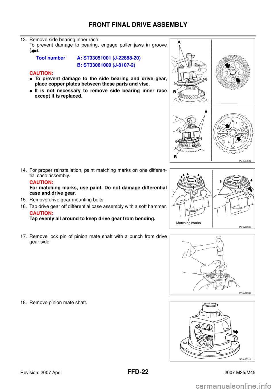
13. Remove side bearing inner race.
To prevent damage to bearing, engage puller jaws in groove
().
CAUTION:
�To prevent damage to the side bearing and drive gear,
place copper plates between these parts and vise.
�It is not necessary to remove side bearing inner race
except it is replaced.
14. For proper reinstallation, paint matching marks on one differen-
tial case assembly.
CAUTION:
For matching marks, use paint. Do not damage differential
case and drive gear.
15. Remove drive gear mounting bolts.
16. Tap drive gear off differential case assembly with a soft hammer.
CAUTION:
Tap evenly all around to keep drive gear from bending.
17. Remove lock pin of pinion mate shaft with a punch from drive
gear side.
18. Remove pinion mate shaft.Tool number A: ST33051001 (J-22888-20)
B: ST33061000 (J-8107-2)
PDIA0758J
PDIA0496E
PDIA0759J
SDIA0031J
Page 3078 of 4647
FRONT FINAL DRIVE ASSEMBLY
FFD-23
C
E
F
G
H
I
J
K
L
MA
B
FFD
Revision: 2007 April2007 M35/M45
19. Turn pinion mate gear, then remove pinion mate gears, pinion
mate thrust washers, side gears and side gear thrust washers
from differential case.
Drive Pinion Assembly
1. Remove differential assembly. Refer to FFD-20, "Differential Assembly" .
2. Remove drive pinion lock nut with a flange wrench.
3. Put matching mark (B) on the end of drive pinion. The matching
mark should be in line with the matching mark (A) on companion
flange (1).
CAUTION:
For matching mark, use paint. Do not damage companion
flange and drive pinion.
NOTE:
The matching mark (A) on the final drive companion flange (1)
indicates the maximum vertical runout position.
When replacing companion flange, matching mark is not neces-
sary.
4. Remove companion flange using the suitable puller.
SDIA0032J
PDIA0798J
PDIA0799J
SDIA1132E
Page 3083 of 4647

FFD-28
FRONT FINAL DRIVE ASSEMBLY
Revision: 2007 April2007 M35/M45
3. Temporarily tighten removed drive pinion lock nut to drive pinion.
NOTE:
Use removed drive pinion lock nut only for the preload measure-
ment.
4. Rotate drive pinion at least 20 times to check for smooth opera-
tion of the bearing.
5. Tighten to drive pinion lock nut, while adjust pinion bearing pre-
load torque.
CAUTION:
�Adjust to the lower limit of the drive pinion lock nut tight-
ening torque first.
�After adjustment, rotate drive pinion back and forth 2 to 3
times to check for unusual noise, rotation malfunction,
and other malfunctions.
6. If the pinion bearing preload torque is outside the specification,
use a thicker/thinner drive pinion bearing adjusting washer and drive pinion adjusting washer to adjust.
Refer to FFD-36, "
Drive Pinion Bearing Adjusting Washer" and FFD-36, "Drive Pinion Adjusting Washer" .
7. Remove companion flange, after adjustment.
ASSEMBLY
Drive Pinion Assembly
1. Install pinion front and rear bearing outer races using drifts.
CAUTION:
�At first, using a hammer, tap bearing outer race until it
becomes flat to gear carrier.
�Do not reuse pinion front and rear bearing outer race.Tool number A: ST3127S000 (J-25765-A)
Drive pinion lock nut tightening torque:
127.4 - 245.0 N·m (13.0 - 25.0 kg-m, 94 - 181 ft-lb)
Pinion bearing preload:
0.78 - 1.57 N·m (0.08 - 0.16 kg-m, 7 - 13 in-lb)
When the preload torque is large:
Decrease the drive pinion bearing adjusting washer and drive pinion adjusting
washer thickness.
When the preload is small:
Increase the drive pinion bearing adjusting washer and drive pinion adjusting
washer thickness.
PDIA0802J
Tool number A: ST37820000 ( — )
PDIA0803J
Page 3085 of 4647
.
NOTE:
When reusing drive pinion, align the matching mark (B) of drive
pinion with the matching mark")
FFD-30
FRONT FINAL DRIVE ASSEMBLY
Revision: 2007 April2007 M35/M45
10. Install companion flange (1).
NOTE:
When reusing drive pinion, align the matching mark (B) of drive
pinion with the matching mark (A) of companion flange, and then
install companion flange (1).
11. Apply anti-corrosion oil to the thread and seat of new drive pin-
ion lock nut, and temporarily tighten drive pinion lock nut to drive
pinion.
CAUTION:
Do not reuse drive pinion lock nut.
12. Tighten to drive pinion lock nut, while adjust pinion bearing pre-
load torque.
CAUTION:
�Adjust to the lower limit of the drive pinion lock nut tight-
ening torque first.
�After adjustment, rotate drive pinion back and forth 2 to 3
times to check for unusual noise, rotation malfunction,
and other malfunctions.
13. Install differential case assembly. Refer to FFD-30, "
Differential
Assembly" .
CAUTION:
Do not install carrier cover yet.
14. Check and adjust drive gear runout, tooth contact, drive gear to drive pinion backlash, and companion
flange runout. Refer to FFD-17, "
Drive Gear Runout" , FFD-17, "Tooth Contact" , FFD-19, "Backlash" ,
FFD-19, "
Companion Flange Runout" .
Recheck above items. Readjust the above description, if necessary.
15. Check total preload torque. Refer to FFD-16, "
Total Preload Torque" .
16. Install carrier cover. Refer to FFD-30, "
Differential Assembly" .
Differential Assembly
1. Install side gear thrust washers with the same thickness as the
ones installed prior to disassembly or reinstall the old ones on
the side gears.
PDIA0799J
Tool number A: ST3127S000 (J-25765-A)
Drive pinion lock nut tightening torque:
127.4 - 245.0 N·m (13.0 - 25.0 kg-m, 94 - 181 ft-lb)
Pinion bearing preload:
0.78 - 1.57 N·m (0.08 - 0.16 kg-m, 7 - 13 in-lb)
PDIA0802J
SDIA0193J