Page 4531 of 4647
TF-42
REAR OIL SEAL
Revision: 2007 April2007 M35/M45
INSTALLATION
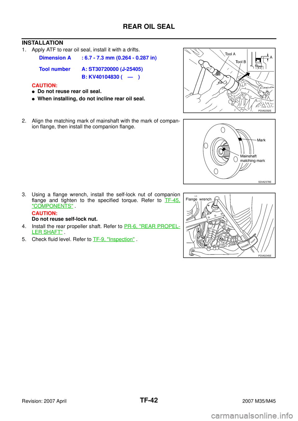
1. Apply ATF to rear oil seal, install it with a drifts.
CAUTION:
�Do not reuse rear oil seal.
�When installing, do not incline rear oil seal.
2. Align the matching mark of mainshaft with the mark of compan-
ion flange, then install the companion flange.
3. Using a flange wrench, install the self-lock nut of companion
flange and tighten to the specified torque. Refer to TF-45,
"COMPONENTS" .
CAUTION:
Do not reuse self-lock nut.
4. Install the rear propeller shaft. Refer to PR-6, "
REAR PROPEL-
LER SHAFT" .
5. Check fluid level. Refer to TF-9, "
Inspection" . Dimension A : 6.7 - 7.3 mm (0.264 - 0.287 in)
Tool number A: ST30720000 (J-25405)
B: KV40104830 ( — )
PDIA0292E
SDIA2378E
PDIA0245E
Page 4534 of 4647
TRANSFER ASSEMBLY
TF-45
C
E
F
G
H
I
J
K
L
MA
B
TF
Revision: 2007 April2007 M35/M45
Disassembly and AssemblyNDS000E5
COMPONENTS
*: This may not be used for December ′06 models or later. 1. Drive chain 2. Front drive shaft rear bearing 3. Front drive shaft
4. Front drive shaft front bearing 5. Sprocket 6. Mainshaft
7. Needle bearing 8. Snap ring 9. Mainshaft bearing
10. Front case 11. Front oil seal 12. Mainshaft oil seal
13. Oil cover 14. Temperature sensor* 15. Electric controlled coupling
16. Spacer 17. Snap ring 18. O-ring
19. Oil gutter 20. Drain plug 21. Baffle plate
22. Rear bearing 23. Snap ring 24. Spacer
25. Rear oil seal 26. Companion flange 27. Self-lock nut
28. Breather tube 29. Rear case 30. Harness bracket
31. Retainer 32. Filler plug 33. Gasket
PDIA0244E
Page 4535 of 4647
TF-46
TRANSFER ASSEMBLY
Revision: 2007 April2007 M35/M45
DISASSEMBLY
Front Case and Rear Case
1. Remove drain plug and filler plug.
2. Remove mainshaft oil seal from front case, using a flat-bladed
screwdriver.
CAUTION:
Be careful not to damage the front case and mainshaft.
3. Remove front oil seal from front case, using a flat-bladed screw-
driver.
CAUTION:
Be careful not to damage the front case and front drive
shaft.
4. Remove self-lock nut.
5. Put a matching mark on the end of mainshaft. The mark should
be in line with the mark on the companion flange.
CAUTION:
For matching mark, use paint. Do not damage mainshaft.
6. Remove companion flange, using a puller.
CAUTION:
Be careful not to damage the companion flange.
PDIA0253E
PDIA0255E
SDIA2378E
PDIA0258E
Page 4546 of 4647

TRANSFER ASSEMBLY
TF-57
C
E
F
G
H
I
J
K
L
MA
B
TF
Revision: 2007 April2007 M35/M45
20. Install rear oil seal to rear case, using the drifts.
CAUTION:
�Do not reuse rear oil seal.
�Apply ATF to rear oil seal.
�When installing, do not incline rear oil seal.
21. Install companion flange while align the matching mark of main-
shaft with the mark of companion flange.
22. Tighten self-lock nut to the specified torque, with flange wrench.
Refer to TF-45, "
COMPONENTS" .
CAUTION:
Do not reuse self-lock nut.
23. Install mainshaft oil seal until it is flush with end face of front
case, using the drift.
CAUTION:
�Do not reuse mainshaft oil seal.
�Apply ATF to mainshaft oil seal.
�When installing, do not incline mainshaft oil seal.
24. Install front oil seal until it is flush with end face of front case,
using the drift.
CAUTION:
�Do not reuse front oil seal.
�Apply ATF to front oil seal.
�When installing, do not incline front oil seal.
25. Apply sealant to threads of drain plug. Then install it to rear case
and tighten to the specified torque. Refer to TF-45, "
COMPO-
NENTS" . Dimension A : 6.7 - 7.3 mm (0.264 - 0.287 in)
Tool number A: ST30720000 (J-25405)
B: KV40104830 ( — )
PDIA0281E
SDIA2378E
SDIA2369E
Tool number : ST30720000 (J-25405)
PDIA0282E
Tool number : ST27862000 ( — )
PDIA0287E
Page 4589 of 4647

WT-40
REMOVAL AND INSTALLATION
Revision: 2007 April2007 M35/M45
3. Place wheel on turntable of tire machine. Ensure that transmitter
is 270 degree from mounting head when second side of tire is
fitted.
NOTE:
Do not touch transmitter at mounting head.
4. Lubricate tire well and fit second side of tire as normal. Ensure
that tire does not rotate relative to rim.
5. Inflate tire and fit to appropriate wheel position.
Low Tire Pressure Warning Control UnitNES000KN
REMOVAL
1. Remove instrument driver lower panel. Refer to IP-10, "INSTRUMENT PANEL ASSEMBLY" .
2. Remove fixing bolt (1), and then remove low tire pressure warn-
ing control unit (2) from vehicle.
INSTALLATION
Installation is the reverse order of removal.
ReceiverNES000KO
REMOVAL
1. Remove tire from vehicle with a power tool.
2. Remove fender protector from vehicle. Refer to EI-20, "
FENDER PROTECTOR" .
3. Remove fixing bolt, then remove tire pressure receiver from vehicle.
INSTALLATION
Installation is the reverse order of removal. For tightening torque, refer to WT-40, "REMOVAL" .
SEIA0048E
SEIA0659E
1. Tire pressure receiver front 2. Tire pressure receiver rear
A. Front wheel house
B. Rear wheel house
Refer to GI-11, "
Components" , for the symbols in the figure.
SEIA0649E
Page 4594 of 4647
 “AIR BAG” and “SEAT
BELT PRE-TENSIONER”
NKS")
PRECAUTION
WW-3
C
D
E
F
G
H
I
J
L
MA
B
WW
Revision: 2007 April2007 M35/M45
PRECAUTION PFP:00011
Precautions for Supplemental Restraint System (SRS) “AIR BAG” and “SEAT
BELT PRE-TENSIONER”
NKS003WA
The Supplemental Restraint System such as “AIR BAG” and “SEAT BELT PRE-TENSIONER”, used along
with a front seat belt, helps to reduce the risk or severity of injury to the driver and front passenger for certain
types of collision. This system includes seat belt switch inputs and dual stage front air bag modules. The SRS
system uses the seat belt switches to determine the front air bag deployment, and may only deploy one front
air bag, depending on the severity of a collision and whether the front occupants are belted or unbelted.
Information necessary to service the system safely is included in the SRS and SB section of this Service Man-
ual.
WARNING:
�To avoid rendering the SRS inoperative, which could increase the risk of personal injury or death
in the event of a collision which would result in air bag inflation, all maintenance must be per-
formed by an authorized NISSAN/INFINITI dealer.
�Improper maintenance, including incorrect removal and installation of the SRS, can lead to per-
sonal injury caused by unintentional activation of the system. For removal of Spiral Cable and Air
Bag Module, see the SRS section.
�Do not use electrical test equipment on any circuit related to the SRS unless instructed to in this
Service Manual. SRS wiring harnesses can be identified by yellow and/or orange harnesses or
harness connectors.
Page 4638 of 4647
FRONT WIPER AND WASHER SYSTEM
WW-47
C
D
E
F
G
H
I
J
L
MA
B
WW
Revision: 2007 April2007 M35/M45
Inspection for Washer Nozzle NKS003X4
CHECK VALVE INSPECTION
Blow air in the injection direction, and make sure that air flows only
one way. Make sure that the reverse direction (inhale) is not possi-
ble.
Inspection of Front Wiper and Washer Switch CircuitNKS003X5
Refer to LT- 2 3 9 , "Combination Switch Inspection" .
Removal and Installation of Front Wiper and Washer SwitchNKS003X6
REMOVAL
1. Remove steering column cover. Refer to IP-10, "INSTRUMENT PANEL ASSEMBLY" .
2. Disconnect the wiper and washer switch connector.
3. Pull wiper and washer switch (1) toward the passenger door
while pressing pawls (A) in direction shown by the arrow in the
figure, and remove it from the base.
INSTALLATION
Installation is the reverse order of removal.
SKIB4256E
SKIB4257E
Page 4642 of 4647
CIGARETTE LIGHTER
WW-51
C
D
E
F
G
H
I
J
L
MA
B
WW
Revision: 2007 April2007 M35/M45
Removal and InstallationNKS003XA
REMOVAL
1. Remove A/T console finisher. Refer to IP-10, "INSTRUMENT PANEL ASSEMBLY" .
2. Remove screws (A) from reverse side cigarette lighter socket.
3. Pull out cigarette lighter (1).
4. Insert a small screwdriver or similar tool between the cigarette
lighter socket (2) and cigarette lighter ring (3). Pull out cigarette
lighter socket (2).
INSTALLATION
Note the following, and installation is the reverse order of removal.
CAUTION:
Align notches of cigarette lighter ring and cigarette lighter socket when installing.
SKIB4207E
SKIB4262E