Page 1454 of 4647
![INFINITI M35 2007 Factory Service Manual UNIFIED METER AND A/C AMP
DI-35
C
D
E
F
G
H
I
J
L
MA
B
DI
Revision: 2007 April2007 M35/M45
DTC [U1000] CAN Communication CircuitNKS003UK
Symptom: Displays “CAN COMM CIRC [U1000]” as a self-diagnos INFINITI M35 2007 Factory Service Manual UNIFIED METER AND A/C AMP
DI-35
C
D
E
F
G
H
I
J
L
MA
B
DI
Revision: 2007 April2007 M35/M45
DTC [U1000] CAN Communication CircuitNKS003UK
Symptom: Displays “CAN COMM CIRC [U1000]” as a self-diagnos](/manual-img/42/57024/w960_57024-1453.png)
UNIFIED METER AND A/C AMP
DI-35
C
D
E
F
G
H
I
J
L
MA
B
DI
Revision: 2007 April2007 M35/M45
DTC [U1000] CAN Communication CircuitNKS003UK
Symptom: Displays “CAN COMM CIRC [U1000]” as a self-diagnosis results of unified meter and A/C amp.
1. CHECK CAN COMMUNICATION
1. Select “SELF-DIAG RESULTS” mode for “METER A/C AMP” with CONSULT-II.
2. Print out CONSULT-II screen.
>> Go to “LAN system”. Refer to LAN-44, "
CAN Diagnostic Support Monitor" .
DTC [B2202] Meter Communication CircuitNKS003UL
Symptom: Displays “METER COMM CIRC [B2202]” as a self-diagnosis results of unified meter and A/C amp.
1. CHECK CONNECTOR
Check combination meter, unified meter and A/C amp. and terminals (combination meter side, unified meter
and A/C amp. side, and harness side) for looseness or bent.
OK or NG
OK >> GO TO 2.
NG >> Repair terminal or connector.
2. CHECK CONTINUITY COMMUNICATION CIRCUIT (TX: UNIFIED METER AND A/C AMP.)
1. Turn ignition switch OFF.
2. Disconnect combination meter connector and unified meter and A/C amp. connector.
3. Check continuity between combination meter harness connector
(A) and unified meter and A/C amp. harness connector (B).
4. Check continuity between combination meter harness connector
(A) and ground.
OK or NG
OK >> GO TO 3.
NG >> Repair harness or connector.
AB
Continuity
Connector Terminal Connector Terminal
M52 15 M64 7 Yes
A
GroundContinuity
Connector Terminal
M52 15 No
PKIB7647E
Page 1457 of 4647
DI-38
UNIFIED METER AND A/C AMP
Revision: 2007 April2007 M35/M45
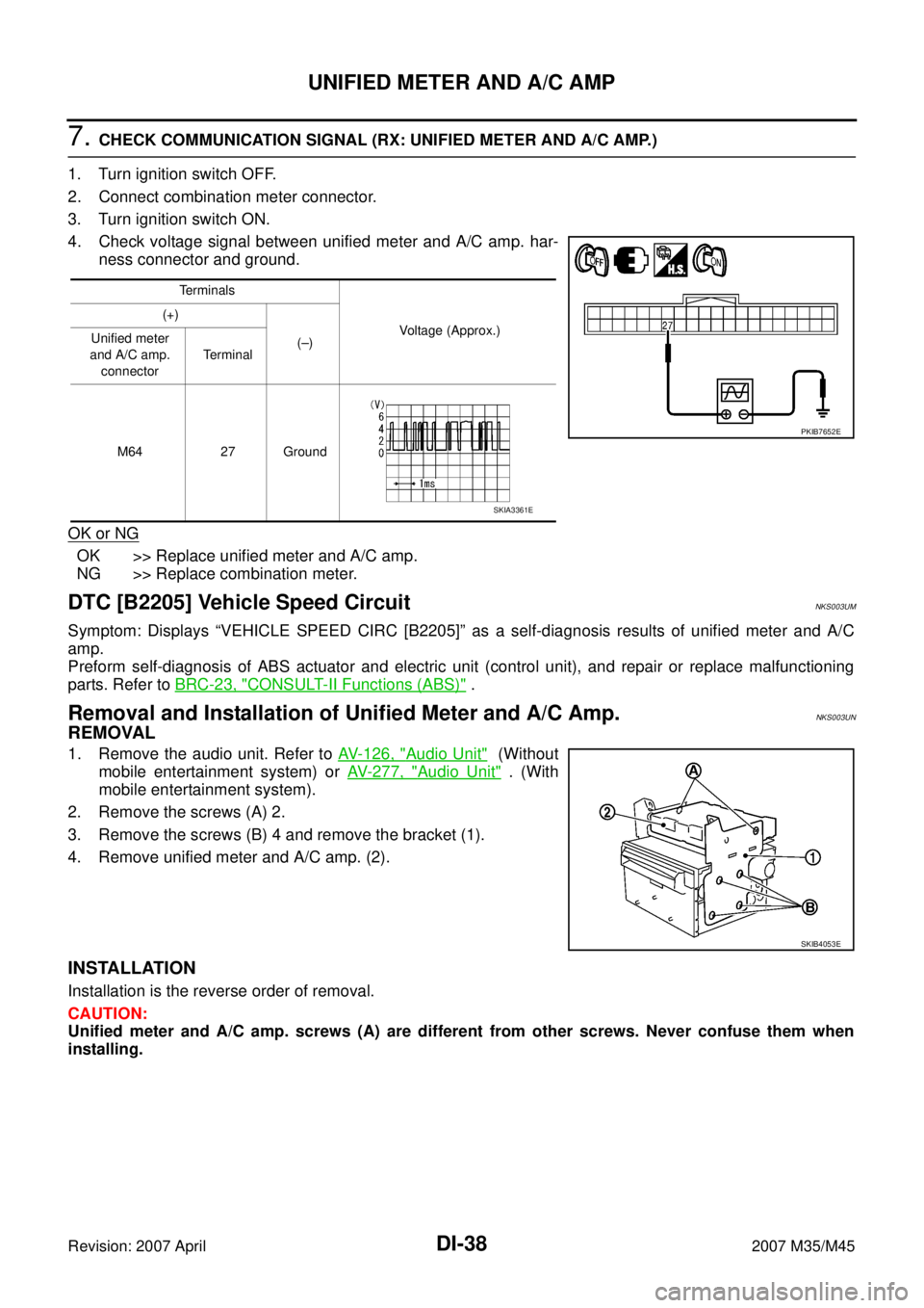
7. CHECK COMMUNICATION SIGNAL (RX: UNIFIED METER AND A/C AMP.)
1. Turn ignition switch OFF.
2. Connect combination meter connector.
3. Turn ignition switch ON.
4. Check voltage signal between unified meter and A/C amp. har-
ness connector and ground.
OK or NG
OK >> Replace unified meter and A/C amp.
NG >> Replace combination meter.
DTC [B2205] Vehicle Speed CircuitNKS003UM
Symptom: Displays “VEHICLE SPEED CIRC [B2205]” as a self-diagnosis results of unified meter and A/C
amp.
Preform self-diagnosis of ABS actuator and electric unit (control unit), and repair or replace malfunctioning
parts. Refer to BRC-23, "
CONSULT-II Functions (ABS)" .
Removal and Installation of Unified Meter and A/C Amp. NKS003UN
REMOVAL
1. Remove the audio unit. Refer to AV- 1 2 6 , "Audio Unit" (Without
mobile entertainment system) or AV- 2 7 7 , "
Audio Unit" . (With
mobile entertainment system).
2. Remove the screws (A) 2.
3. Remove the screws (B) 4 and remove the bracket (1).
4. Remove unified meter and A/C amp. (2).
INSTALLATION
Installation is the reverse order of removal.
CAUTION:
Unified meter and A/C amp. screws (A) are different from other screws. Never confuse them when
installing.
Terminals
Voltage (Approx.) (+)
(–) Unified meter
and A/C amp.
connectorTerminal
M64 27 Ground
PKIB7652E
SKIA3361E
SKIB4053E
Page 1474 of 4647
A/T INDICATOR
DI-55
C
D
E
F
G
H
I
J
L
MA
B
DI
Revision: 2007 April2007 M35/M45
A/T INDICATORPFP:24814
System DescriptionNKS003UV
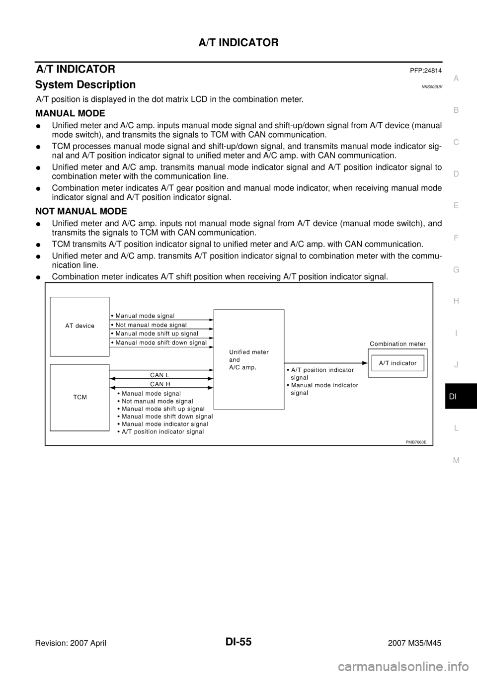
A/T position is displayed in the dot matrix LCD in the combination meter.
MANUAL MODE
�Unified meter and A/C amp. inputs manual mode signal and shift-up/down signal from A/T device (manual
mode switch), and transmits the signals to TCM with CAN communication.
�TCM processes manual mode signal and shift-up/down signal, and transmits manual mode indicator sig-
nal and A/T position indicator signal to unified meter and A/C amp. with CAN communication.
�Unified meter and A/C amp. transmits manual mode indicator signal and A/T position indicator signal to
combination meter with the communication line.
�Combination meter indicates A/T gear position and manual mode indicator, when receiving manual mode
indicator signal and A/T position indicator signal.
NOT MANUAL MODE
�Unified meter and A/C amp. inputs not manual mode signal from A/T device (manual mode switch), and
transmits the signals to TCM with CAN communication.
�TCM transmits A/T position indicator signal to unified meter and A/C amp. with CAN communication.
�Unified meter and A/C amp. transmits A/T position indicator signal to combination meter with the commu-
nication line.
�Combination meter indicates A/T shift position when receiving A/T position indicator signal.
PKIB7660E
Page 1477 of 4647
DI-58
A/T INDICATOR
Revision: 2007 April2007 M35/M45
A/T Indicator Is MalfunctionNKS003UX
1. CHECK SEGMENTS OF A/T INDICATOR
Perform self-diagnosis mode of combination meter. Refer to DI-17, "
OPERATION PROCEDURE" .
Are all segments displayed?
YES >> GO TO 2.
NO >> Replace combination meter.
2. CHECK UNIFIED METER AND A/C AMP. (CONSULT-II)
Perform self-diagnosis of unified meter and A/C amp. Refer to DI-31, "
CONSULT-II Function (METER A/C
AMP)" .
Self
-diagnostic results content
No malfunction detected>> GO TO 3.
Malfunction detected>> Check applicable parts, and repair or replace corresponding parts.
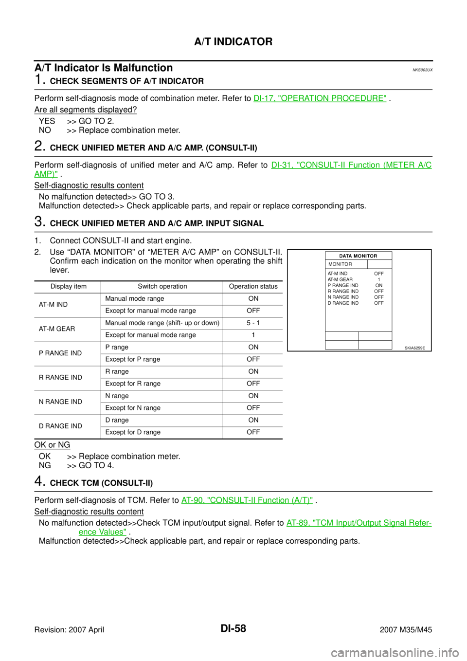
3. CHECK UNIFIED METER AND A/C AMP. INPUT SIGNAL
1. Connect CONSULT-II and start engine.
2. Use “DATA MONITOR” of “METER A/C AMP” on CONSULT-II.
Confirm each indication on the monitor when operating the shift
lever.
OK or NG
OK >> Replace combination meter.
NG >> GO TO 4.
4. CHECK TCM (CONSULT-II)
Perform self-diagnosis of TCM. Refer to AT- 9 0 , "
CONSULT-II Function (A/T)" .
Self-diagnostic results content
No malfunction detected>>Check TCM input/output signal. Refer to AT- 8 9 , "TCM Input/Output Signal Refer-
ence Values" .
Malfunction detected>>Check applicable part, and repair or replace corresponding parts.
Display item Switch operation Operation status
AT - M I N DManual mode range ON
Except for manual mode range OFF
AT - M G E A RManual mode range (shift- up or down) 5 - 1
Except for manual mode range 1
P RANGE INDP range ON
Except for P range OFF
R RANGE INDR range ON
Except for R range OFF
N RANGE INDN range ON
Except for N range OFF
D RANGE INDD range ON
Except for D range OFF
SKIA6259E
Page 1487 of 4647
DI-68
WARNING CHIME
Revision: 2007 April2007 M35/M45
CONSULT-II Function (BCM)NKS003V5
CONSULT-II can display each diagnostic item using the diagnostic test modes shown following.
CONSULT-II BASIC OPERATION
Refer to GI-38, "CONSULT-II Start Procedure" .
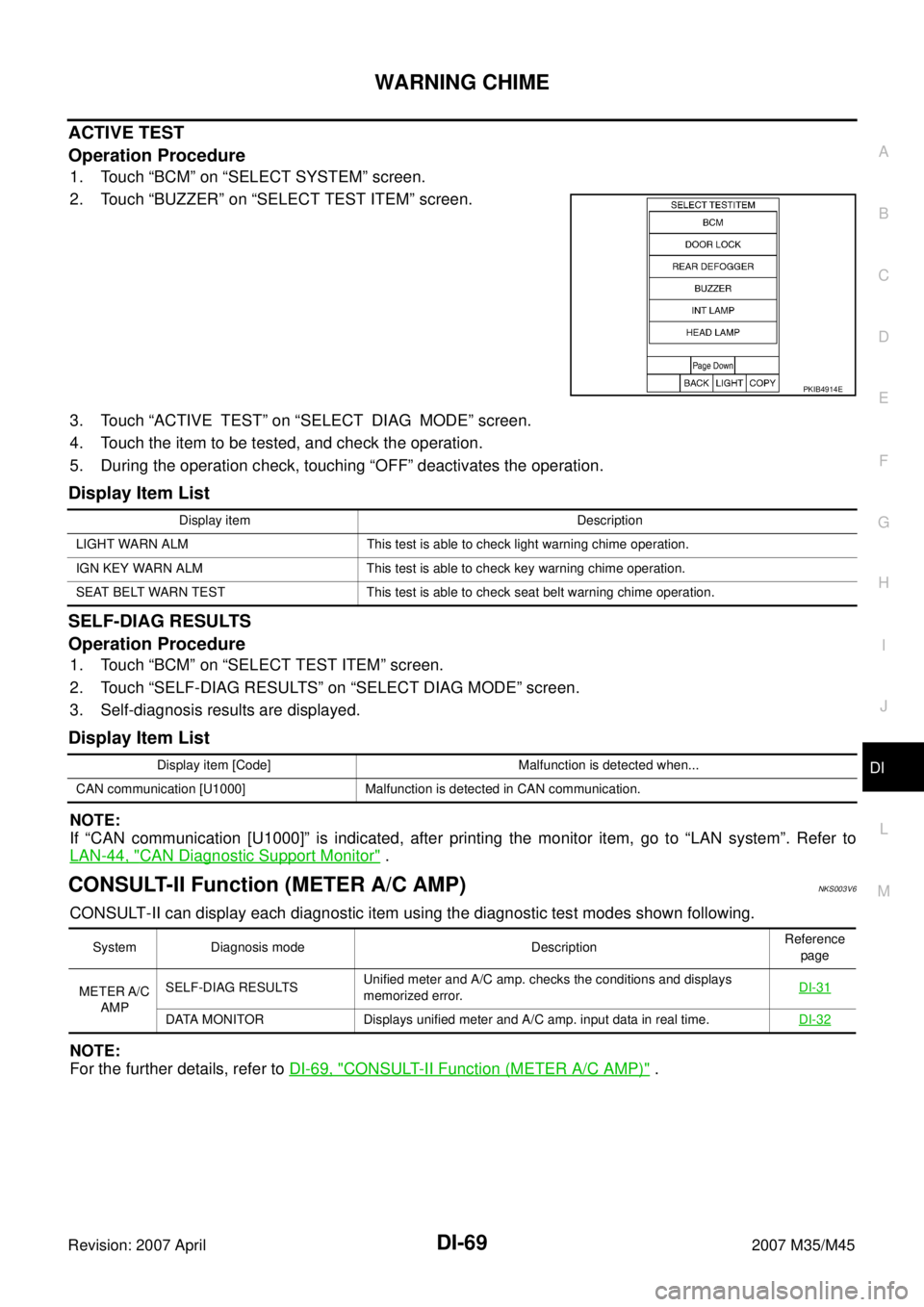
DATA MONITOR
Operation Procedure
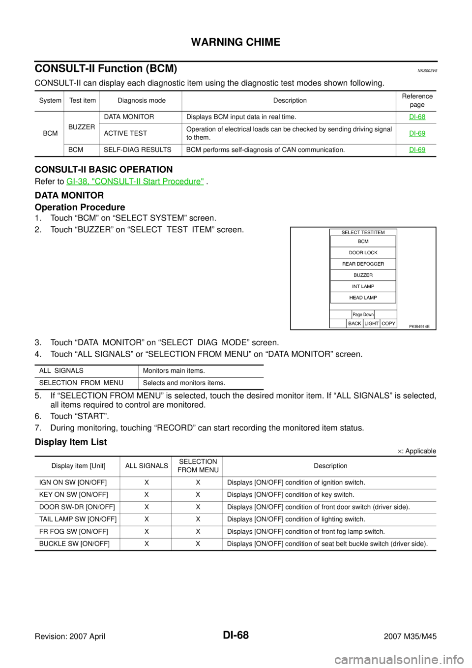
1. Touch “BCM” on “SELECT SYSTEM” screen.
2. Touch “BUZZER” on “SELECT TEST ITEM” screen.
3. Touch “DATA MONITOR” on “SELECT DIAG MODE” screen.
4. Touch “ALL SIGNALS” or “SELECTION FROM MENU” on “DATA MONITOR” screen.
5. If “SELECTION FROM MENU” is selected, touch the desired monitor item. If “ALL SIGNALS” is selected,
all items required to control are monitored.
6. Touch “START”.
7. During monitoring, touching “RECORD” can start recording the monitored item status.
Display Item List
×: Applicable System Test item Diagnosis mode DescriptionReference
page
BCMBUZZERDATA MONITOR Displays BCM input data in real time.DI-68
ACTIVE TESTOperation of electrical loads can be checked by sending driving signal
to them.DI-69
BCM SELF-DIAG RESULTS BCM performs self-diagnosis of CAN communication.DI-69
PKIB4914E
ALL SIGNALS Monitors main items.
SELECTION FROM MENU Selects and monitors items.
Display item [Unit] ALL SIGNALSSELECTION
FROM MENUDescription
IGN ON SW [ON/OFF] X X Displays [ON/OFF] condition of ignition switch.
KEY ON SW [ON/OFF] X X Displays [ON/OFF] condition of key switch.
DOOR SW-DR [ON/OFF] X X Displays [ON/OFF] condition of front door switch (driver side).
TAIL LAMP SW [ON/OFF] X X Displays [ON/OFF] condition of lighting switch.
FR FOG SW [ON/OFF] X X Displays [ON/OFF] condition of front fog lamp switch.
BUCKLE SW [ON/OFF] X X Displays [ON/OFF] condition of seat belt buckle switch (driver side).
Page 1488 of 4647
WARNING CHIME
DI-69
C
D
E
F
G
H
I
J
L
MA
B
DI
Revision: 2007 April2007 M35/M45
ACTIVE TEST
Operation Procedure
1. Touch “BCM” on “SELECT SYSTEM” screen.
2. Touch “BUZZER” on “SELECT TEST ITEM” screen.
3. Touch “ACTIVE TEST” on “SELECT DIAG MODE” screen.
4. Touch the item to be tested, and check the operation.
5. During the operation check, touching “OFF” deactivates the operation.
Display Item List
SELF-DIAG RESULTS
Operation Procedure
1. Touch “BCM” on “SELECT TEST ITEM” screen.
2. Touch “SELF-DIAG RESULTS” on “SELECT DIAG MODE” screen.
3. Self-diagnosis results are displayed.
Display Item List
NOTE:
If “CAN communication [U1000]” is indicated, after printing the monitor item, go to “LAN system”. Refer to
LAN-44, "
CAN Diagnostic Support Monitor" .
CONSULT-II Function (METER A/C AMP)NKS003V6
CONSULT-II can display each diagnostic item using the diagnostic test modes shown following.
NOTE:
For the further details, refer to DI-69, "
CONSULT-II Function (METER A/C AMP)" .
PKIB4914E
Display item Description
LIGHT WARN ALM This test is able to check light warning chime operation.
IGN KEY WARN ALM This test is able to check key warning chime operation.
SEAT BELT WARN TEST This test is able to check seat belt warning chime operation.
Display item [Code] Malfunction is detected when...
CAN communication [U1000] Malfunction is detected in CAN communication.
System Diagnosis mode DescriptionReference
page
METER A/C
AMPSELF-DIAG RESULTSUnified meter and A/C amp. checks the conditions and displays
memorized error.DI-31
DATA MONITOR Displays unified meter and A/C amp. input data in real time.DI-32
Page 1501 of 4647
DI-82
LANE DEPARTURE WARNING SYSTEM
Revision: 2007 April2007 M35/M45
3. Touch “LDW”.
If “LDW” is not displayed, go to GI-39, "
CONSULT-II Data Link
Connector (DLC) Circuit" .
4. Touch “WORK SUPPORT”.
5. Touch “AUTO AIM”.
6. The target should be accurately placed.
The vehicle should be stopped.
After confirming the above, touch “START” to perform aiming.
CAUTION:
Never touch “START” when the target is not placed.
BCIA0030E
BCIA0031E
PKIB4696E
SKIB3146E
Page 1502 of 4647
LANE DEPARTURE WARNING SYSTEM
DI-83
C
D
E
F
G
H
I
J
L
MA
B
DI
Revision: 2007 April2007 M35/M45
7. Touch “NEXT”, then a keyboard window is displayed. Input “Dh”,
and then touch “ENTER”.
NOTE:
Check the value “Dh”. Refer to DI-81, "
VEHICLE HEIGHT
CHECK" .
8. Check the regulated value. (Spec.)
NOTE:
Check the value input at step 8.
a. Touch “NEXT” if appropriate.
b. Touch “CHANGE SET” to change “Dh”.
9. Touch “NEXT”.
CAUTION:
Never change “Ht”.
10. Touch “NEXT”.
CAUTION:
Never change “Dt”.
SKIB3147E
SKIB3148E
SKIB3149E
SKIB3173E