2007 INFINITI M35 fuel system diagram
[x] Cancel search: fuel system diagramPage 2564 of 4647
![INFINITI M35 2007 Factory Service Manual DTC P0172, P0175 FUEL INJECTION SYSTEM FUNCTION
EC-1035
[VK45DE]
C
D
E
F
G
H
I
J
K
L
MA
EC
Revision: 2007 April2007 M35/M45
Wiring DiagramNBS005FF
BANK 1
TBWT1492E INFINITI M35 2007 Factory Service Manual DTC P0172, P0175 FUEL INJECTION SYSTEM FUNCTION
EC-1035
[VK45DE]
C
D
E
F
G
H
I
J
K
L
MA
EC
Revision: 2007 April2007 M35/M45
Wiring DiagramNBS005FF
BANK 1
TBWT1492E](/manual-img/42/57024/w960_57024-2563.png)
DTC P0172, P0175 FUEL INJECTION SYSTEM FUNCTION
EC-1035
[VK45DE]
C
D
E
F
G
H
I
J
K
L
MA
EC
Revision: 2007 April2007 M35/M45
Wiring DiagramNBS005FF
BANK 1
TBWT1492E
Page 2569 of 4647
![INFINITI M35 2007 Factory Service Manual EC-1040
[VK45DE]
DTC P0172, P0175 FUEL INJECTION SYSTEM FUNCTION
Revision: 2007 April2007 M35/M45
3. CHECK AIR FUEL RATIO (A/F) SENSOR 1 INPUT SIGNAL CIRCUIT
1. Turn ignition switch OFF.
2. Disconnect INFINITI M35 2007 Factory Service Manual EC-1040
[VK45DE]
DTC P0172, P0175 FUEL INJECTION SYSTEM FUNCTION
Revision: 2007 April2007 M35/M45
3. CHECK AIR FUEL RATIO (A/F) SENSOR 1 INPUT SIGNAL CIRCUIT
1. Turn ignition switch OFF.
2. Disconnect](/manual-img/42/57024/w960_57024-2568.png)
EC-1040
[VK45DE]
DTC P0172, P0175 FUEL INJECTION SYSTEM FUNCTION
Revision: 2007 April2007 M35/M45
3. CHECK AIR FUEL RATIO (A/F) SENSOR 1 INPUT SIGNAL CIRCUIT
1. Turn ignition switch OFF.
2. Disconnect corresponding air fuel ratio (A/F) sensor 1 harness connector.
3. Disconnect ECM harness connector.
4. Check harness continuity between the following terminals.
Refer to Wiring Diagram.
5. Check harness continuity between the following terminals and ground.
Refer to Wiring Diagram.
6. Also check harness for short to power.
OK or NG
OK >> GO TO 4.
NG >> Repair open circuit or short to ground or short to power in harness or connectors.
: Vehicle front 1. A/F sensor 1 (bank 2)
harness connector2. A/F sensor 1 (bank 1)
harness connector
A/F sensor 1 terminal ECM terminal
Bank 1116
275
535
656
Bank 2176
277
557
658
Continuity should exist.
Bank 1 Bank 2
A/F sensor 1 terminal ECM terminal A/F sensor 1 terminal ECM terminal
116176
275277
535557
656658
Continuity should not exist.
PBIB2715E
Page 3144 of 4647
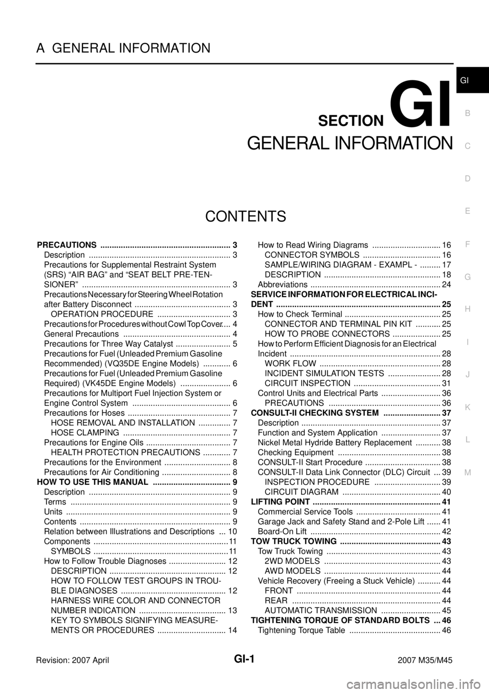
GI-1
GENERAL INFORMATION
A GENERAL INFORMATION
CONTENTS
C
D
E
F
G
H
I
J
K
L
MB
GI
SECTION GI
Revision: 2007 April2007 M35/M45
Revision: 2007 AprilGENERAL INFORMATION
PRECAUTIONS .......................................................... 3
Description ............................................................... 3
Precautions for Supplemental Restraint System
(SRS) “AIR BAG” and “SEAT BELT PRE-TEN-
SIONER” .................................................................. 3
Precautions Necessary for Steering Wheel Rotation
after Battery Disconnect ........................................... 3
OPERATION PROCEDURE ................................. 3
Precautions for Procedures without Cowl Top Cover ..... 4
General Precautions ................................................ 4
Precautions for Three Way Catalyst ......................... 5
Precautions for Fuel (Unleaded Premium Gasoline
Recommended) (VQ35DE Engine Models) ............. 6
Precautions for Fuel (Unleaded Premium Gasoline
Required) (VK45DE Engine Models) ....................... 6
Precautions for Multiport Fuel Injection System or
Engine Control System ............................................ 6
Precautions for Hoses .............................................. 7
HOSE REMOVAL AND INSTALLATION ............... 7
HOSE CLAMPING ................................................ 7
Precautions for Engine Oils ...................................... 7
HEALTH PROTECTION PRECAUTIONS ............. 7
Precautions for the Environment .............................. 8
Precautions for Air Conditioning ............................... 8
HOW TO USE THIS MANUAL ................................... 9
Description ............................................................... 9
Terms ....................................................................... 9
Units ......................................................................... 9
Contents ................................................................... 9
Relation between Illustrations and Descriptions .... 10
Components ............................................................ 11
SYMBOLS ............................................................ 11
How to Follow Trouble Diagnoses .......................... 12
DESCRIPTION .................................................... 12
HOW TO FOLLOW TEST GROUPS IN TROU-
BLE DIAGNOSES ............................................... 12
HARNESS WIRE COLOR AND CONNECTOR
NUMBER INDICATION ....................................... 13
KEY TO SYMBOLS SIGNIFYING MEASURE-
MENTS OR PROCEDURES ............................... 14How to Read Wiring Diagrams ............................... 16
CONNECTOR SYMBOLS ................................... 16
SAMPLE/WIRING DIAGRAM - EXAMPL - .......... 17
DESCRIPTION .................................................... 18
Abbreviations .......................................................... 24
SERVICE INFORMATION FOR ELECTRICAL INCI-
DENT ......................................................................... 25
How to Check Terminal ........................................... 25
CONNECTOR AND TERMINAL PIN KIT ............ 25
HOW TO PROBE CONNECTORS ...................... 25
How to Perform Efficient Diagnosis for an Electrical
Incident ................................................................... 28
WORK FLOW ...................................................... 28
INCIDENT SIMULATION TESTS ........................ 28
CIRCUIT INSPECTION ....................................... 31
Control Units and Electrical Parts ........................... 36
PRECAUTIONS .................................................. 36
CONSULT-II CHECKING SYSTEM .......................... 37
Description .............................................................. 37
Function and System Application ........................... 37
Nickel Metal Hydride Battery Replacement ............ 38
Checking Equipment .............................................. 38
CONSULT-II Start Procedure .................................. 38
CONSULT-II Data Link Connector (DLC) Circuit .... 39
INSPECTION PROCEDURE .............................. 39
CIRCUIT DIAGRAM ............................................ 40
LIFTING POINT ......................................................... 41
Commercial Service Tools ...................................... 41
Garage Jack and Safety Stand and 2-Pole Lift ....... 41
Board-On Lift .......................................................... 42
TOW TRUCK TOWING ............................................. 43
Tow Truck Towing ................................................... 43
2WD MODELS .................................................... 43
AWD MODELS .................................................... 44
Vehicle Recovery (Freeing a Stuck Vehicle) ........... 44
FRONT ................................................................ 44
REAR .................................................................. 44
AUTOMATIC TRANSMISSION ........................... 45
TIGHTENING TORQUE OF STANDARD BOLTS .... 46
Tightening Torque Table ......................................... 46
Page 3321 of 4647
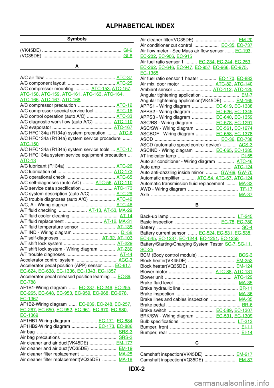
IDX-2
ALPHABETICAL INDEX
Symbols
(VK45DE) .............................................................. GI-6
(VQ35DE) ............................................................. GI-6
A
A/C air flow ...................................................... ATC-37
A/C component layout ..................................... ATC-25
A/C compressor mounting ........... ATC-153, ATC-157,
ATC-158
, ATC-159, ATC-161, ATC-163, ATC-164,
ATC-166
, ATC-167, ATC-168
A/C compressor precaution ............................. ATC-12
A/C compressor special service tool ................ ATC-16
A/C control operation (auto A/C) ...................... ATC-33
A/C diagnostic work flow (auto A/C) .............. ATC-110
A/C evaporator ............................................... ATC-167
A/C HFC134a (R134a) system precaution ........ ATC-6
A/C HFC134a (R134a) system service procedure .......
ATC-150
A/C HFC134a (R134a) system service tools ... ATC-17
A/C HFC134a system service equipment precaution ...
ATC-13
A/C lubricant (R134a) ...................................... ATC-26
A/C lubrication oil ........................................... ATC-173
A/C operational check ...................................... ATC-65
A/C self-diagnoses (auto A/C) ........ ATC-56, ATC-110
A/C service data specification ........................ ATC-173
A/C system description (auto A/C) ................... ATC-29
A/C trouble diagnoses (auto A/C) .................... ATC-40
A/C, A - Wiring diagram ................................... ATC-46
A/T fluid checking ...................... AT-13, AT-53, MA-29
A/T fluid cooler cleaning .................................... AT-14
A/T fluid replacement ............................. AT-12, MA-31
A/T fluid temperature sensor ........................... AT-135
A/T IND - Wiring diagram .................................... DI-56
A/T self-diagnoses ............................... AT-92, AT-103
A/T shift lock system ........................................ AT-229
A/T shift lock system - Wiring diagram ............ AT-230
A/T trouble diagnoses ........................................ AT-44
Accelerator control system ............................... ACC-3
Accelerator pedal position (APP) sensor ........ EC-617,
EC-624
, EC-638, EC-1336, EC-1343, EC-1357
Accelerator pedal released position learning .... EC-86,
EC-788
AF1B1-Wiring diagram ...... EC-237, EC-246, EC-255,
EC-265
, EC-648, EC-950, EC-959, EC-968, EC-978,
EC-1367
AF1B2-Wiring diagram ...... EC-239, EC-248, EC-257,
EC-267
, EC-650, EC-952, EC-961, EC-970, EC-980,
EC-1369
AF1HB1-Wiring diagram .................... EC-171, EC-884
AF1HB2-Wiring diagram .................... EC-173, EC-886
Air bag .............................................................. SRS-3
Air bag precautions ........................................... SRS-3
Air cleaner and air duct(VK45DE) ................... EM-177
Air cleaner and air duct(VQ35DE) .................... EM-19
Air cleaner filter replacement ............................ MA-25
Air cleaner filter replacement(VQ35DE) ........... MA-18
Air cleaner filter(VQ35DE) ................................ EM-20
Air conditioner cut control ................... EC-35, EC-737
Air flow meter - See Mass air flow sensor ....... EC-193,
EC-202
, EC-906, EC-915
Air fuel ratio sensor 1 ......... EC-234, EC-244, EC-253,
EC-262
, EC-646, EC-947, EC-957, EC-966, EC-975,
EC-1365
Air fuel ratio sensor 1 heater ............. EC-170, EC-883
Air mix. door motor ......................... ATC-82, ATC-140
Ambient sensor ............................. ATC-112, ATC-125
Angular tightening application ............................. EM-7
Angular tightening application(VK45DE) ........ EM-165
APPS1 - Wiring diagram ................. EC-619, EC-1338
APPS2 - Wiring diagram ................. EC-626, EC-1345
APPS3 - Wiring diagram ................. EC-640, EC-1359
ASC/BS - Wiring diagram ............... EC-578, EC-1291
ASC/SW - Wiring diagram .............. EC-561, EC-1274
ASCBOF - Wiring diagram .............. EC-658, EC-1378
ASCD .................................................. EC-36, EC-738
ASCD (automatic speed control device) ........... ACS-3
ASCIND - Wiring diagram ............... EC-665, EC-1385
AT indicator lamp ................................................ DI-55
Auto air conditioner - Wiring diagram ............. ATC-46
Auto amp ...................................................... ATC-124
Auto anti-dazzling inside mirror .......... GW-69, GW-70
Automatic amplifier ........... ATC-54, ATC-67, ATC-124
Automatic transmission fluid replacement ........ MA-32
AWD - Wiring diagram ....................................... TF-17
Axle ................................................................... MA-37
B
Back-up lamp ................................................... LT-245
Basic inspection .................................. EC-78, EC-780
Battery ................................................................. SC-4
Battery current sensor ....... EC-524, EC-531, EC-538,
EC-545
, EC-1237, EC-1244, EC-1251, EC-1258
Battery/Starting/Charging System Tester SC-7, SC-11,
SC-25
BCM (Body control module) .............................. BCS-3
Block heater(VK45DE) .................................... EM-252
Block heater(VQ35DE) ................................... EM-124
Blower motor ................................... ATC-88, ATC-131
Blower unit .................................................... ATC-129
Brake fluid level ................................................ MA-35
Brake hydraulic line ........................................... BR-11
Brake inspection ............................................... MA-36
Brake lines and cables inspection .................... MA-35
Brake pedal .......................................................... BR-6
Brake switch ................................... EC-589, EC-1307
BRK/SW - Wiring diagram .............. EC-591, EC-1309
Bulb specifications ........................................... LT-313
Bumper, front ...................................................... EI-11
Bumper, rear ....................................................... EI-14
C
Camshaft inspection(VK45DE) ....................... EM-217
Camshaft inspection(VQ35DE) ......................... EM-87
Page 3323 of 4647
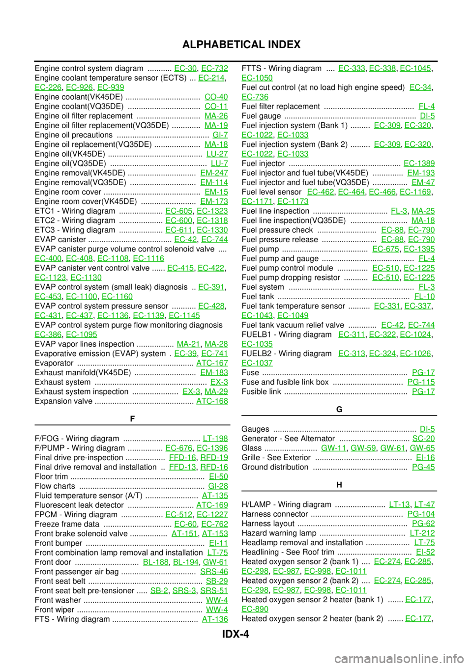
IDX-4
ALPHABETICAL INDEX
Engine control system diagram ........... EC-30, EC-732
Engine coolant temperature sensor (ECTS) ... EC-214,
EC-226
, EC-926, EC-939
Engine coolant(VK45DE) .................................. CO-40
Engine coolant(VQ35DE) ................................. CO-11
Engine oil filter replacement ............................. MA-26
Engine oil filter replacement(VQ35DE) ............. MA-19
Engine oil precautions .......................................... GI-7
Engine oil replacement(VQ35DE) ..................... MA-18
Engine oil(VK45DE) ........................................... LU-27
Engine oil(VQ35DE) ............................................ LU-7
Engine removal(VK45DE) ............................... EM-247
Engine removal(VQ35DE) .............................. EM-114
Engine room cover ............................................ EM-15
Engine room cover(VK45DE) ......................... EM-173
ETC1 - Wiring diagram .................... EC-605, EC-1323
ETC2 - Wiring diagram .................... EC-600, EC-1318
ETC3 - Wiring diagram .................... EC-611, EC-1330
EVAP canister ...................................... EC-42, EC-744
EVAP canister purge volume control solenoid valve ....
EC-400
, EC-408, EC-1108, EC-1116
EVAP canister vent control valve ...... EC-415, EC-422,
EC-1123
, EC-1130
EVAP control system (small leak) diagnosis .. EC-391,
EC-453
, EC-1100, EC-1160
EVAP control system pressure sensor ........... EC-428,
EC-431
, EC-437, EC-1136, EC-1139, EC-1145
EVAP control system purge flow monitoring diagnosis
EC-386
, EC-1095
EVAP vapor lines inspection ................. MA-21, MA-28
Evaporative emission (EVAP) system . EC-39, EC-741
Evaporator ..................................................... ATC-167
Exhaust manifold(VK45DE) ............................ EM-183
Exhaust system ................................................... EX-3
Exhaust system inspection ..................... EX-3, MA-29
Expansion valve ............................................. ATC-168
F
F/FOG - Wiring diagram ................................... LT-198
F/PUMP - Wiring diagram ................ EC-676, EC-1396
Final drive pre-inspection .................. FFD-16, RFD-19
Final drive removal and installation .. FFD-13, RFD-16
Floor trim ............................................................. EI-50
Flow charts ......................................................... GI-28
Fluid temperature sensor (A/T) ........................ AT-135
Fluorescent leak detector .............................. ATC-169
FPCM - Wiring diagram ................... EC-512, EC-1227
Freeze frame data ............................... EC-60, EC-762
Front brake solenoid valve ................. AT-151, AT-153
Front bumper ...................................................... EI-11
Front combination lamp removal and installation LT-75
Front door ............................. BL-188, BL-194, GW-61
Front passenger air bag .................................. SRS-46
Front seat belt .................................................... SB-29
Front seat belt pre-tensioner ..... SB-2, SRS-3, SRS-51
Front washer ...................................................... WW-4
Front wiper ......................................................... WW-4
FTS - Wiring diagram ....................................... AT-136
FTTS - Wiring diagram .... EC-333, EC-338, EC-1045,
EC-1050
Fuel cut control (at no load high engine speed) EC-34,
EC-736
Fuel filter replacement ......................................... FL-4
Fuel gauge ............................................................ DI-5
Fuel injection system (Bank 1) ......... EC-309, EC-320,
EC-1022
, EC-1033
Fuel injection system (Bank 2) ......... EC-309, EC-320,
EC-1022
, EC-1033
Fuel injector ................................................... EC-1389
Fuel injector and fuel tube(VK45DE) .............. EM-193
Fuel injector and fuel tube(VQ35DE) ................ EM-47
Fuel level sensor EC-462, EC-464, EC-466, EC-1169,
EC-1171
, EC-1173
Fuel line inspection .................................. FL-3, MA-25
Fuel line inspection(VQ35DE) .......................... MA-18
Fuel pressure check ........................... EC-88, EC-790
Fuel pressure release ......................... EC-88, EC-790
Fuel pump ....................................... EC-675, EC-1395
Fuel pump and gauge .......................................... FL-4
Fuel pump control module .............. EC-510, EC-1225
Fuel pump dropping resistor ........... EC-510, EC-1225
Fuel system ......................................................... FL-3
Fuel tank ............................................................ FL-10
Fuel tank temperature sensor .......... EC-331, EC-337,
EC-1043
, EC-1049
Fuel tank vacuum relief valve ............. EC-42, EC-744
FUELB1 - Wiring diagram EC-311, EC-322, EC-1024,
EC-1035
FUELB2 - Wiring diagram EC-313, EC-324, EC-1026,
EC-1037
Fuse .................................................................. PG-17
Fuse and fusible link box ................................ PG-115
Fusible link ........................................................ PG-17
G
Gauges ................................................................. DI-5
Generator - See Alternator ................................ SC-20
Glass ........................ GW-11, GW-59, GW-61, GW-65
Grille - See Exterior ............................................ EI-16
Ground distribution ........................................... PG-45
H
H/LAMP - Wiring diagram ....................... LT-13
, LT-47
Harness connector .......................................... PG-104
Harness layout .................................................. PG-62
Hazard warning lamp ....................................... LT-212
Headlamp removal and installation .................... LT-75
Headlining - See Roof trim .................................. EI-52
Heated oxygen sensor 2 (bank 1) .... EC-274, EC-285,
EC-298
, EC-987, EC-998, EC-1011
Heated oxygen sensor 2 (bank 2) .... EC-274, EC-285,
EC-298
, EC-987, EC-998, EC-1011
Heated oxygen sensor 2 heater (bank 1) ....... EC-177,
EC-890
Heated oxygen sensor 2 heater (bank 2) ....... EC-177,
Page 3325 of 4647
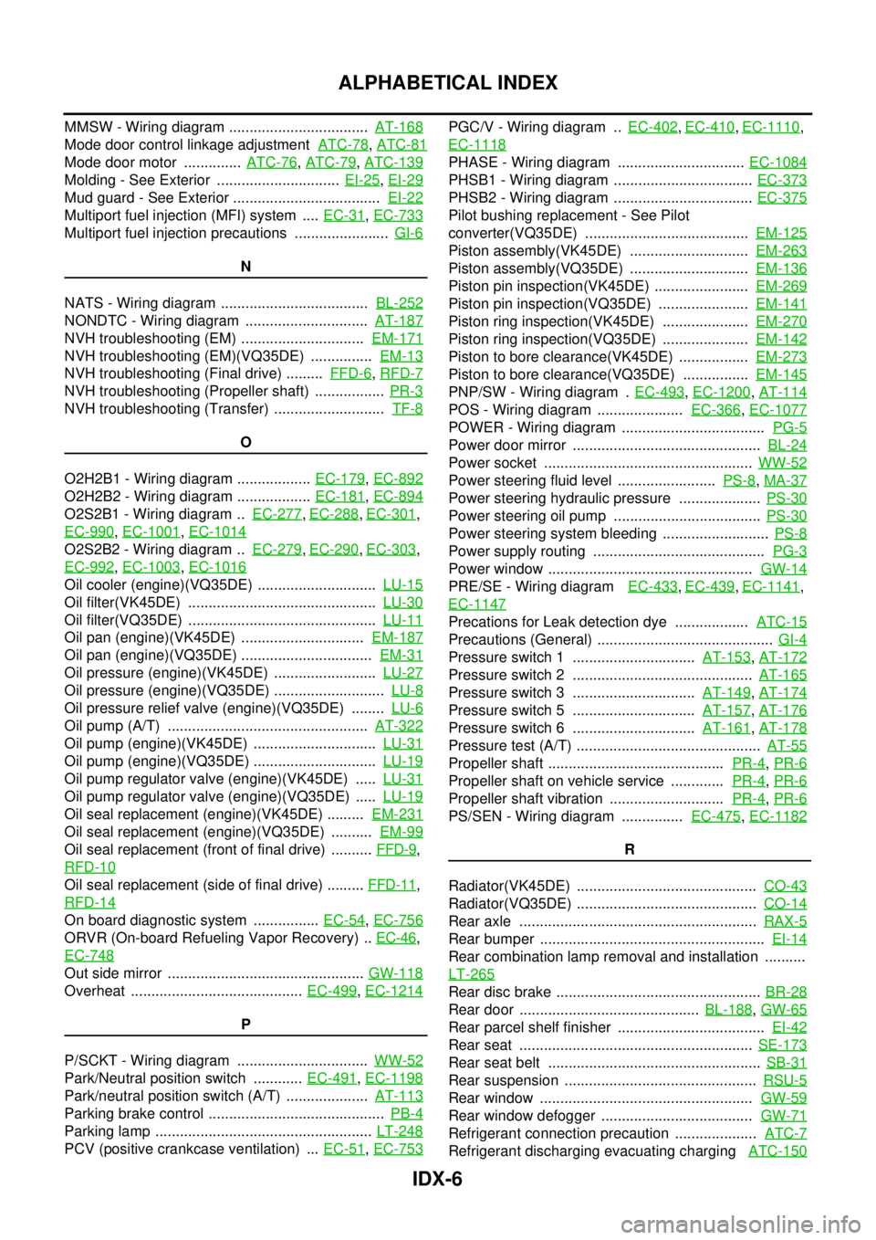
IDX-6
ALPHABETICAL INDEX
MMSW - Wiring diagram .................................. AT-168
Mode door control linkage adjustment ATC-78, ATC-81
Mode door motor .............. ATC-76, ATC-79, ATC-139
Molding - See Exterior .............................. EI-25, EI-29
Mud guard - See Exterior .................................... EI-22
Multiport fuel injection (MFI) system .... EC-31, EC-733
Multiport fuel injection precautions ....................... GI-6
N
NATS - Wiring diagram .................................... BL-252
NONDTC - Wiring diagram .............................. AT-187
NVH troubleshooting (EM) .............................. EM-171
NVH troubleshooting (EM)(VQ35DE) ............... EM-13
NVH troubleshooting (Final drive) ......... FFD-6, RFD-7
NVH troubleshooting (Propeller shaft) ................. PR-3
NVH troubleshooting (Transfer) ........................... TF-8
O
O2H2B1 - Wiring diagram .................. EC-179
, EC-892
O2H2B2 - Wiring diagram .................. EC-181, EC-894
O2S2B1 - Wiring diagram .. EC-277, EC-288, EC-301,
EC-990
, EC-1001, EC-1014
O2S2B2 - Wiring diagram .. EC-279, EC-290, EC-303,
EC-992
, EC-1003, EC-1016
Oil cooler (engine)(VQ35DE) ............................. LU-15
Oil filter(VK45DE) .............................................. LU-30
Oil filter(VQ35DE) .............................................. LU-11
Oil pan (engine)(VK45DE) .............................. EM-187
Oil pan (engine)(VQ35DE) ................................ EM-31
Oil pressure (engine)(VK45DE) ......................... LU-27
Oil pressure (engine)(VQ35DE) ........................... LU-8
Oil pressure relief valve (engine)(VQ35DE) ........ LU-6
Oil pump (A/T) ................................................. AT-322
Oil pump (engine)(VK45DE) .............................. LU-31
Oil pump (engine)(VQ35DE) .............................. LU-19
Oil pump regulator valve (engine)(VK45DE) ..... LU-31
Oil pump regulator valve (engine)(VQ35DE) ..... LU-19
Oil seal replacement (engine)(VK45DE) ......... EM-231
Oil seal replacement (engine)(VQ35DE) .......... EM-99
Oil seal replacement (front of final drive) .......... FFD-9,
RFD-10
Oil seal replacement (side of final drive) ......... FFD-11,
RFD-14
On board diagnostic system ................ EC-54, EC-756
ORVR (On-board Refueling Vapor Recovery) .. EC-46,
EC-748
Out side mirror ................................................ GW-118
Overheat .......................................... EC-499, EC-1214
P
P/SCKT - Wiring diagram ................................ WW-52
Park/Neutral position switch ............ EC-491, EC-1198
Park/neutral position switch (A/T) .................... AT-113
Parking brake control ........................................... PB-4
Parking lamp ..................................................... LT-248
PCV (positive crankcase ventilation) ... EC-51, EC-753
PGC/V - Wiring diagram .. EC-402, EC-410, EC-1110,
EC-1118
PHASE - Wiring diagram ............................... EC-1084
PHSB1 - Wiring diagram .................................. EC-373
PHSB2 - Wiring diagram .................................. EC-375
Pilot bushing replacement - See Pilot
converter(VQ35DE) ........................................ EM-125
Piston assembly(VK45DE) ............................. EM-263
Piston assembly(VQ35DE) ............................. EM-136
Piston pin inspection(VK45DE) ....................... EM-269
Piston pin inspection(VQ35DE) ...................... EM-141
Piston ring inspection(VK45DE) ..................... EM-270
Piston ring inspection(VQ35DE) ..................... EM-142
Piston to bore clearance(VK45DE) ................. EM-273
Piston to bore clearance(VQ35DE) ................ EM-145
PNP/SW - Wiring diagram . EC-493, EC-1200, AT-114
POS - Wiring diagram ..................... EC-366, EC-1077
POWER - Wiring diagram ................................... PG-5
Power door mirror .............................................. BL-24
Power socket ................................................... WW-52
Power steering fluid level ........................ PS-8, MA-37
Power steering hydraulic pressure .................... PS-30
Power steering oil pump .................................... PS-30
Power steering system bleeding .......................... PS-8
Power supply routing .......................................... PG-3
Power window .................................................. GW-14
PRE/SE - Wiring diagram EC-433, EC-439, EC-1141,
EC-1147
Precations for Leak detection dye .................. ATC-15
Precautions (General) ........................................... GI-4
Pressure switch 1 .............................. AT-153, AT-172
Pressure switch 2 ............................................ AT-165
Pressure switch 3 .............................. AT-149, AT-174
Pressure switch 5 .............................. AT-157, AT-176
Pressure switch 6 .............................. AT-161, AT-178
Pressure test (A/T) ............................................. AT-55
Propeller shaft ........................................... PR-4, PR-6
Propeller shaft on vehicle service ............. PR-4, PR-6
Propeller shaft vibration ............................ PR-4, PR-6
PS/SEN - Wiring diagram ............... EC-475, EC-1182
R
Radiator(VK45DE) ............................................ CO-43
Radiator(VQ35DE) ............................................ CO-14
Rear axle .......................................................... RAX-5
Rear bumper ....................................................... EI-14
Rear combination lamp removal and installation ..........
LT-265
Rear disc brake .................................................. BR-28
Rear door ............................................ BL-188, GW-65
Rear parcel shelf finisher .................................... EI-42
Rear seat ......................................................... SE-173
Rear seat belt .................................................... SB-31
Rear suspension ............................................... RSU-5
Rear window .................................................... GW-59
Rear window defogger ..................................... GW-71
Refrigerant connection precaution .................... ATC-7
Refrigerant discharging evacuating charging ATC-150
Page 3946 of 4647
HARNESS
PG-95
C
D
E
F
G
H
I
J
L
MA
B
PG
Revision: 2007 April2007 M35/M45
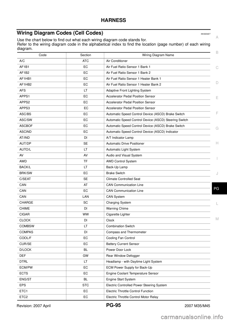
Wiring Diagram Codes (Cell Codes) NKS004ET
Use the chart below to find out what each wiring diagram code stands for.
Refer to the wiring diagram code in the alphabetical index to find the location (page number) of each wiring
diagram.
Code Section Wiring Diagram Name
A/C ATC Air Conditioner
AF1B1 EC Air Fuel Ratio Sensor 1 Bank 1
AF1B2 EC Air Fuel Ratio Sensor 1 Bank 2
AF1HB1 EC Air Fuel Ratio Sensor 1 Heater Bank 1
AF1HB2 EC Air Fuel Ratio Sensor 1 Heater Bank 2
AFS LT Adaptive Front Lighting System
APPS1 EC Accelerator Pedal Position Sensor
APPS2 EC Accelerator Pedal Position Sensor
APPS3 EC Accelerator Pedal Position Sensor
ASC/BS EC Automatic Speed Control Device (ASCD) Brake Switch
ASC/SW EC Automatic Speed Control Device (ASCD) Steering Switch
ASCBOF EC Automatic Speed Control Device (ASCD) Brake Switch
ASCIND EC Automatic Speed Control Device (ASCD) Indicator
AT/IND DI A/T Indicator Lamp
AUT/DP SE Automatic Drive Positioner
AUTO/L LT Automatic Light System
AV AV Audio and Visual System
AWD TF AWD Control System
BACK/L LT Back-Up Lamp
BRK/SW EC Brake Switch
C/SEAT SE Climate Controlled Seat
CAN AT CAN Communication Line
CAN EC CAN Communication Line
CAN LAN CAN System
CHARGE SC Charging System
CHIME DI Warning Chime
CIGAR WW Cigarette Lighter
CLOCK DI Clock
COMBSW LT Combination Switch
COMPAS DI Compass and Thermometer
COOL/F EC Cooling Fan Control
CUR/SE EC Battery Current Sensor
D/LOCK BL Power Door Lock
DEF GW Rear Window Defogger
DTRL LT Headlamp - with Daytime Light System
ECM/PW EC ECM Power Supply for Back-Up
ECTS EC Engine Coolant Temperature Sensor
ENG/ST BL Engine Start System
EPS STC Electric Controlled Power Steering System
ETC1 EC Electric Throttle Control Function
ETC2 EC Electric Throttle Control Motor Relay
Page 3947 of 4647

PG-96
HARNESS
Revision: 2007 April2007 M35/M45
ETC3 EC Electric Throttle Control Motor
F/FOG LT Front Fog Lamp
F/PUMP EC Fuel Pump
FPCM EC Fuel Pump Control Module
FTS AT A/T Fluid Temperature Sensor Circuit
FTTS EC Fuel Tank Temperature Sensor
FUELB1 EC Fuel Injection System Function (Bank 1)
FUELB2 EC Fuel Injection System Function (Bank 2)
H/LAMP LT Headlamp
HORN WW Horn
HSEAT SE Heated Seat
I/KEY BL Intelligent Key System
I/MIRR GW Inside Mirror (Auto Anti-Dazzling Mirror)
IATS EC Intake Air Temperature Sensor
ICC ACS Intelligent Cruise Control System
ICC/BS EC ICC Brake Switch
ICC/SW EC ICC Steering Switch
ICCBOF EC ICC Brake Switch
IGNSYS EC Ignition System
ILL LT Illumination
INJECT EC Injector
IVCB1 EC Intake Valve Timing Control Solenoid Valve Bank 1
IVCB2 EC Intake Valve Timing Control Solenoid Valve Bank 2
IVCSB1 EC Intake Valve Timing Control Position Sensor Bank 1
IVCSB2 EC Intake Valve Timing Control Position Sensor Bank 2
IVTB1 EC Intake Valve Timing Control System (Bank 1)
IVTB2 EC Intake Valve Timing Control System (Bank 2)
KS EC Knock Sensor
LDW DI Lane Departure Warning System
MAFS EC Mass Air Flow Sensor
MAIN AT Main Power Supply and Ground Circuit
MAIN EC Main Power Supply and Ground Circuit
METER DI Speedometer, Tachometer, Temp., Oil and Fuel Gauges
MIL/DL EC MIL & Data Link Connector
MIRROR GW Door Mirror
MMSW AT Manual Mode Switch
NATS BL Nissan Anti-Theft System
NONDTC AT Non-Detective Items
O2H2B1 EC Heated Oxygen Sensor 2 Heater Bank 1
O2H2B2 EC Heated Oxygen Sensor 2 Heater Bank 2
O2S2B1 EC Heated Oxygen Sensor 2 Bank 1
O2S2B2 EC Heated Oxygen Sensor 2 Bank 2
P/SCKT WW Power Socket
PDU PG Power Distribution Unit Code Section Wiring Diagram Name