Page 2999 of 4647
EI-28
DOOR SASH MOLDING
Revision: 2007 April2007 M35/M45
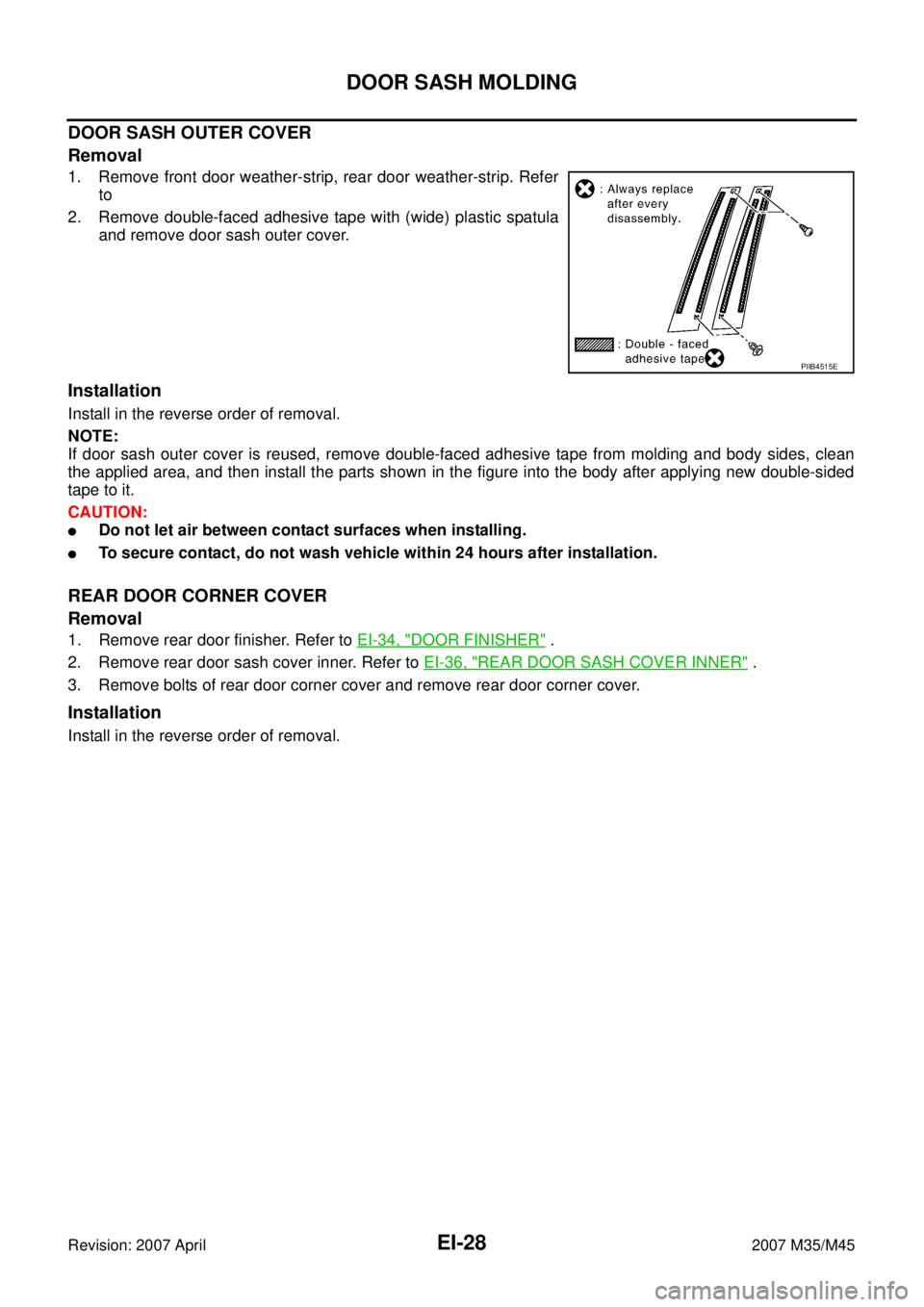
DOOR SASH OUTER COVER
Removal
1. Remove front door weather-strip, rear door weather-strip. Refer
to
2. Remove double-faced adhesive tape with (wide) plastic spatula
and remove door sash outer cover.
Installation
Install in the reverse order of removal.
NOTE:
If door sash outer cover is reused, remove double-faced adhesive tape from molding and body sides, clean
the applied area, and then install the parts shown in the figure into the body after applying new double-sided
tape to it.
CAUTION:
�Do not let air between contact surfaces when installing.
�To secure contact, do not wash vehicle within 24 hours after installation.
REAR DOOR CORNER COVER
Removal
1. Remove rear door finisher. Refer to EI-34, "DOOR FINISHER" .
2. Remove rear door sash cover inner. Refer to EI-36, "
REAR DOOR SASH COVER INNER" .
3. Remove bolts of rear door corner cover and remove rear door corner cover.
Installation
Install in the reverse order of removal.
PIIB4515E
Page 3001 of 4647
EI-30
DOOR OUTSIDE MOLDING
Revision: 2007 April2007 M35/M45
CAUTION:
�Be careful not to apply excessive force when removing because it is easy to deform parts.
�After removal, visually inspect molding, and if it is deformed, replace it with new molding.
Installation
Install in the reverse order of removal.
NOTE:
Molding rear end is flush with door sash rear end when installing.
REAR DOOR OUTSIDE MOLDING
Removal
1. Fully open door window.
2. Remove door trim. Refer to EI-34, "
DOOR FINISHER" .
3. Remove rear door sash cover inner. Refer to EI-36, "
REAR DOOR SASH COVER INNER" .
4. Disengage pawls by inserting a screwdriver to front and rear of pawl integrated with cap.
5. Remove door outside molding while pulling up molding using plastic spatula after disengaging.
CAUTION:
�Be careful not to apply excessive force when removing because it is easy to deform parts.
�After removal, visually inspect molding, and if it is deformed, replace it with new molding.
Installation
Install in the reverse order of removal.
NOTE:
Molding rear end is flush with door sash rear end when installing.
Page 3004 of 4647
TRUNK LID FINISHER
EI-33
C
D
E
F
G
H
J
K
L
MA
B
EI
Revision: 2007 April2007 M35/M45
TRUNK LID FINISHERPFP:84810
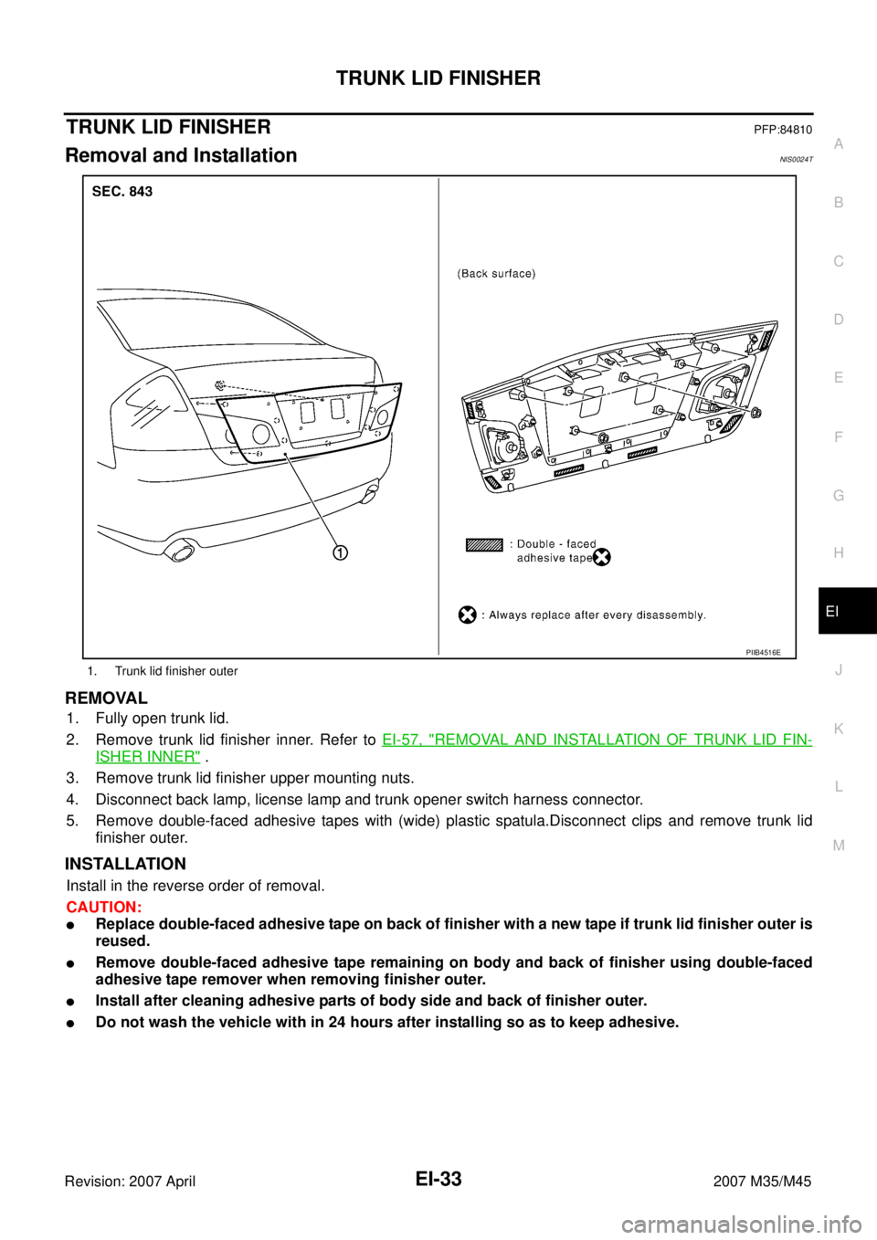
Removal and InstallationNIS0024T
REMOVAL
1. Fully open trunk lid.
2. Remove trunk lid finisher inner. Refer to EI-57, "
REMOVAL AND INSTALLATION OF TRUNK LID FIN-
ISHER INNER" .
3. Remove trunk lid finisher upper mounting nuts.
4. Disconnect back lamp, license lamp and trunk opener switch harness connector.
5. Remove double-faced adhesive tapes with (wide) plastic spatula.Disconnect clips and remove trunk lid
finisher outer.
INSTALLATION
Install in the reverse order of removal.
CAUTION:
�Replace double-faced adhesive tape on back of finisher with a new tape if trunk lid finisher outer is
reused.
�Remove double-faced adhesive tape remaining on body and back of finisher using double-faced
adhesive tape remover when removing finisher outer.
�Install after cleaning adhesive parts of body side and back of finisher outer.
�Do not wash the vehicle with in 24 hours after installing so as to keep adhesive.
1. Trunk lid finisher outer
PIIB4516E
Page 3006 of 4647
DOOR FINISHER
EI-35
C
D
E
F
G
H
J
K
L
MA
B
EI
Revision: 2007 April2007 M35/M45
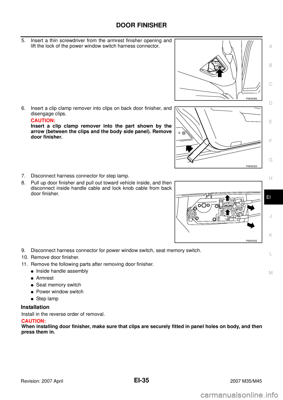
5. Insert a thin screwdriver from the armrest finisher opening and
lift the lock of the power window switch harness connector.
6. Insert a clip clamp remover into clips on back door finisher, and
disengage clips.
CAUTION:
Insert a clip clamp remover into the part shown by the
arrow (between the clips and the body side panel). Remove
door finisher.
7. Disconnect harness connector for step lamp.
8. Pull up door finisher and pull out toward vehicle inside, and then
disconnect inside handle cable and lock knob cable from back
door finisher.
9. Disconnect harness connector for power window switch, seat memory switch.
10. Remove door finisher.
11. Remove the following parts after removing door finisher.
�Inside handle assembly
�Armrest
�Seat memory switch
�Power window switch
�Ste p l am p
Installation
Install in the reverse order of removal.
CAUTION:
When installing door finisher, make sure that clips are securely fitted in panel holes on body, and then
press them in.
PIIB4936E
PIIB4932E
PIIB4933E
Page 3014 of 4647
REAR PARCEL SHELF FINISHER
EI-43
C
D
E
F
G
H
J
K
L
MA
B
EI
Revision: 2007 April2007 M35/M45
4. Remove rear kicking plate inner, rear wheelhouse garnish, rear pillar finisher. Refer to EI-37, "BODY SIDE
TRIM" .
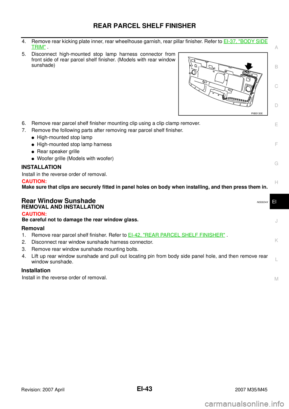
5. Disconnect high-mounted stop lamp harness connector from
front side of rear parcel shelf finisher. (Models with rear window
sunshade)
6. Remove rear parcel shelf finisher mounting clip using a clip clamp remover.
7. Remove the following parts after removing rear parcel shelf finisher.
�High-mounted stop lamp
�High-mounted stop lamp harness
�Rear speaker grille
�Woofer grille (Models with woofer)
INSTALLATION
Install in the reverse order of removal.
CAUTION:
Make sure that clips are securely fitted in panel holes on body when installing, and then press them in.
Rear Window SunshadeNIS0024X
REMOVAL AND INSTALLATION
CAUTION:
Be careful not to damage the rear window glass.
Removal
1. Remove rear parcel shelf finisher. Refer to EI-42, "REAR PARCEL SHELF FINISHER" .
2. Disconnect rear window sunshade harness connector.
3. Remove rear window sunshade mounting bolts.
4. Lift up rear window sunshade and pull out locating pin from body side panel hole, and then remove rear
window sunshade.
Installation
Install in the reverse order of removal.
PIIB5130E
Page 3015 of 4647
EI-44
SUNSHADE
Revision: 2007 April2007 M35/M45
SUNSHADEPFP:97580
Component Parts and Harness Connector LocationNIS0024Y
PIIB5864E
1. Fuse block (J/B) 2. Back-up lamp relay E19 3.Rear sunshade cancel relay B141
(View with the trunk side finisher RH
removed)
4.Rear sunshade unit (With built-in
motor) B474
(View with the rear parcel shelf fin-
isher removed)5.a: Rear sunshade front switch M137
b: Rear control cancel switch M1516. Rear sunshade rear switch B557
Page 3025 of 4647
EI-54
HEADLINING
Revision: 2007 April2007 M35/M45
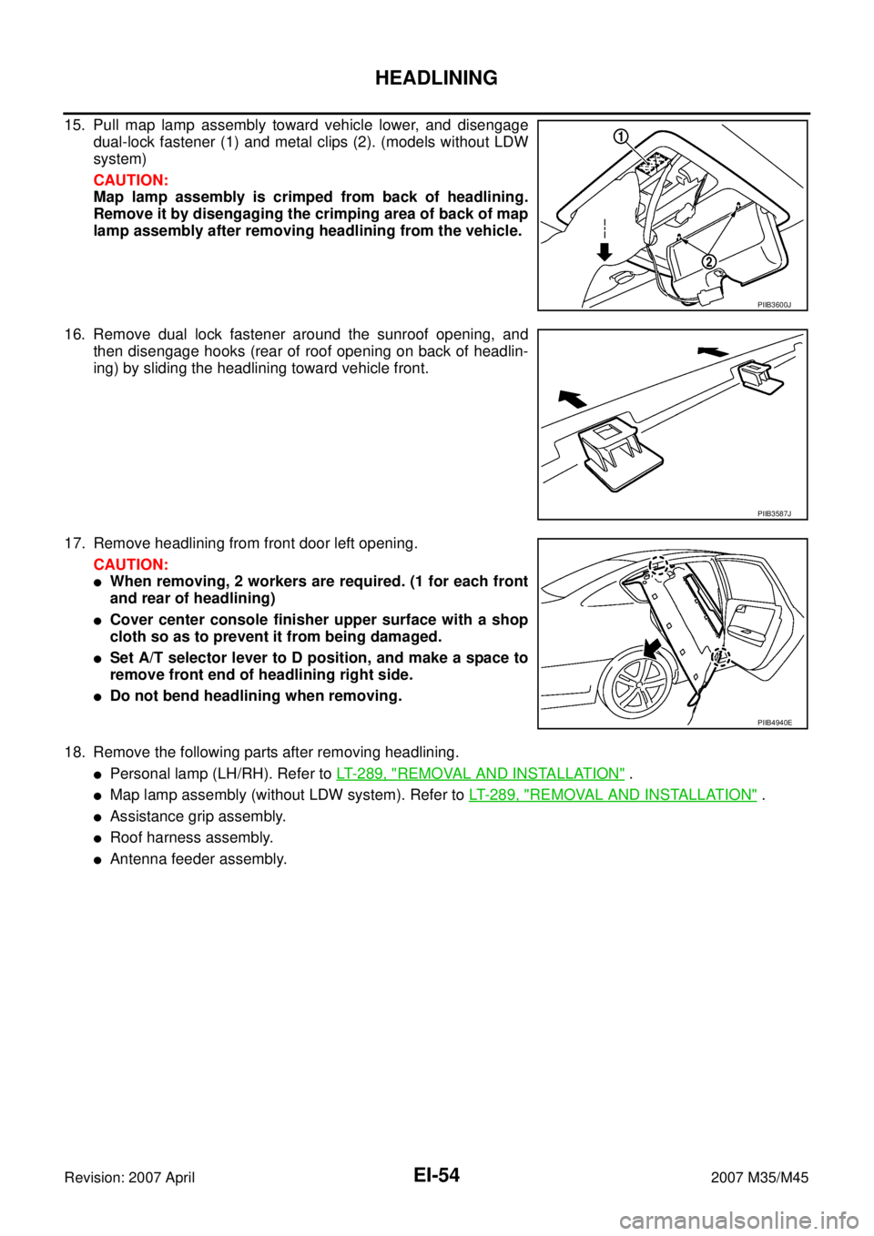
15. Pull map lamp assembly toward vehicle lower, and disengage
dual-lock fastener (1) and metal clips (2). (models without LDW
system)
CAUTION:
Map lamp assembly is crimped from back of headlining.
Remove it by disengaging the crimping area of back of map
lamp assembly after removing headlining from the vehicle.
16. Remove dual lock fastener around the sunroof opening, and
then disengage hooks (rear of roof opening on back of headlin-
ing) by sliding the headlining toward vehicle front.
17. Remove headlining from front door left opening.
CAUTION:
�When removing, 2 workers are required. (1 for each front
and rear of headlining)
�Cover center console finisher upper surface with a shop
cloth so as to prevent it from being damaged.
�Set A/T selector lever to D position, and make a space to
remove front end of headlining right side.
�Do not bend headlining when removing.
18. Remove the following parts after removing headlining.
�Personal lamp (LH/RH). Refer to LT- 2 8 9 , "REMOVAL AND INSTALLATION" .
�Map lamp assembly (without LDW system). Refer to LT- 2 8 9 , "REMOVAL AND INSTALLATION" .
�Assistance grip assembly.
�Roof harness assembly.
�Antenna feeder assembly.
PIIB3600J
PIIB3587J
PIIB4940E
Page 3032 of 4647
EXHAUST SYSTEM
EX-3
C
D
E
F
G
H
I
J
K
L
MA
EX
Revision: 2007 April2007 M35/M45
EXHAUST SYSTEMPFP:20100
Checking Exhaust SystemNBS005RJ
Check exhaust pipes, muffler and mounting for improper attachment,
leaks, cracks, damage or deterioration.
�If anything is found, repair or replace damaged parts.
SMA211A